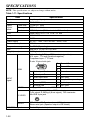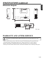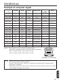
1
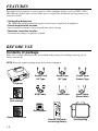
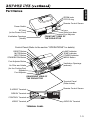
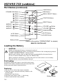
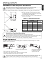
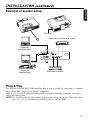
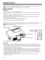
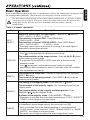
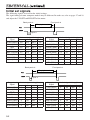
CP-S220W
USER'S MANUAL
Thank you for purchasing this HITACHI liquid crystal projector.
Please read the accompanying manual “SAFETY INSTRUCTIONS” and this “USER'S
MANUAL” thoroughly to ensure correct usage through understanding. After reading,
store this instruction manual in a safe place for future reference.
NOTE:
* The information in this manual is subject to change without notice.
* The manufacturer assumes no responsibility for any errors that may appear in this manual
* The reproduction, transmission or use of this documents or contents is not permitted without
express written authority.
TRADEMARK ACKNOWLEDGMENT:
* PS/2, VGA and XGA are registered trademark of International Business Machines Corporation.
* Apple, Macintosh, Mac and ADB are registered trademarks of Apple Computer, Inc.
* VESA and SVGA are trademarks of the Video Electronics Standard Association.
* Windows is registered trademarks of Microsoft Corporation.
* Carefully observe the trademarks and registered trademarks of all companies, even when not
mentioned.
CONTENTS
FEATURES
BEFORE USE
Contents of Package
Part Names
Loading the Battery
INSTALLATION
Installation of the projector and Screen
Angle Adjustment
Cabling
Power Connection
Example of System Setup
Plug & Play
OPERATIONS
Power On/Off
Basic Operation
Menu Functions
TROUBLESHOOTING
OSD Message
Indicators Message
Symptom
Warranty and After-service
SPECIFICATIONS
Tables:
Table 1-1. Installation Reference
Table 1-2. Basic Operations
Table 1-3. Menu Functions
Table 1-4. OSD Message
Table 1-5. Indicator Message
Table 1-6. Symptom
Table 1-7. Specifications
Table 1-8. Example of Compatible Signal
MAINTENANCE
Cleaning
Lamp
1-1
ENGLISH
Liquid Crystal Projector
FEATURES
This liquid crystal projector is used to project various computer signals as well as NTSC / PAL /
SECAM video signals onto a screen. Little space is required for installation and large images can
easily be realized.
• Outstanding brightness
The UHB lamp and high-efficiency optical system assure a high level of brightness.
• Partial magnification function
Interesting parts of images can be magnified for closer viewing.
• Distortion correction function
Distortion-free images are quickly available.
BEFORE USE
Contents of package
Make sure all of the following items are included in the package. If anything is missing, please
contact your dealer.
NOTE: Keep the original packing material for future reshipment.
Power Cord
US Type
Power Cord
UK Type
Power Cord
Europe Type
Projector
RGB Cable
Video Cable
Audio Cable
(Stereo Mini)
User’s Manual
(this manual)
VIDEO
STANDBY/ON
RGB
MENU
SELECT
MENU
Mac Adapter
MAGNIFY
POSITION RESET
FREEZE VOLUME
MUTE
OFF
AUTO
TIMER
BLANK
Safety Instructions
Remote Controller
containing Battery
1-2
Carrying Bag
B E F O R E U S E ( c o n t i nu e d )
ENGLISH
Part Names
ZOOM knob
FOCUS ring
Remote Control Sensor
Power Switch
Lens
Slide Lens door
Foot Adjuster
FRONT/LEFT VIEW OF
THE PROJECTOR
AC Inlet
(to the Power Cord)
Ventilation Openings
(Intake)
Control Panel (Refer to the section "OPERATIONS" for details)
LAMP Indicator
TEMP Indicator
POWER Indicator
MENU Button
RESET Button
MUTE Button
INPUT Button
STANDBY/ON Button
Foot Adjuster Button
Ventilation Openings
(exhaust)
Air Filter and Intake
(for the Cooling Fan)
Speaker
Foot Adjuster
REAR/RIGHT VIEW OF
THE PROJECTOR
Terminal Panel
(Refer below)
Remote Control Sensor
S-VIDEO Terminal
RGB IN Terminal
CONTROL Terminal
AUDIO IN Terminal
VIDEO Terminal
TERMINAL PANEL
1-3
BEFORE USE (continued)
Part Names (continued)
VIDEO Button
STANDBY/ON Button
VIDEO
STANDBY/ON
RGB
Button
RGB Button
MENU SELECT Button
Button
MENU
SELECT
Button
POSITION Button
Button
MENU
MENU Button
MAGNIFY
RESET Button
Button
MAGNIFY
MAGNIFY
POSITION RESET
Button
OFF
MAGNIFY
FREEZE VOLUME
Button
MUTE
OFF
AUTO
TIMER
BLANK
AUTO Button
Button
VOLUME
Button
FREEZE Button
MUTE Button
BLANK Button
TIMER Button
Battery Holder
VOLUME
(Refer to the section "OPERATIONS" for details)
REMOTE CONTROLLER
Loading the Battery
CAUTION
Danger of explosion if battery is incorrectly replaced.
Be careful in handling the battery according to instructions of the accompanying manual
“SAFETY INSTRUCTIONS” and this manual.
Replace only with the same or equivalent type recommended by the manufacturer.
Use the 3V micro lithium battery Type no. CR2025 only.
When you dispose the battery, you must obey the law in the relative area or country.
Keep the battery away from children and pets.
First Loading:
In original packing, the battery is installed in the battery
holder of the remote controller with protection film. Pull
out the protection film to load the battery.
“+” side
Replacing:
1. See the reverse side of the remote controller.
2. Pinch the groove and pull out battery holder as the
drawing right.
3. Remove the worn battery.
4. Install the new battery with “+” side facing.
5. Push in and click the battery holder.
1-4
Pull out
Battery Holder
INSTALLATION
ENGLISH
Installation of the Projector and Screen
Install the projector in a suitable environment according to instructions of the
accompanying manual “SAFETY INSTRUCTIONS” and this manual.
Refer to the drawing and table below for determining of the screen size and projection distance.
a: Distance from the LCD projector to the screen.
The projection distance shown in the table below
are for full size (800 x 600 dots).
b: Distance from the lens center to the bottom of the
screen (a, b: +/-10%)
Table 1-1. Installation Reference
TOP VIEW
b
a
a (inches)
Screen size
(inches)
Min.
Max.
40
37
46
3
60
57
69
5
80
77
93
7
100
96
116
9
120
116
139
10
150
145
174
13
200
194
233
17
b (inches)
SIDE VIEW
Installation of liquid crystal projector
Please basically use liquid crystal projector at the horizontal position.
If you use liquid crystal projector by the lens up position, the lens down position and the side up
position, this may cause the heat inside to build up and become the cause of damage.
Be especially careful not to install it with ventilation holes blocked.
Angle Adjustment
Use the foot adjuster on the bottom of the projector to adjust the projection angle. It is variable
within 0˚ to 10˚ approximately.
10°
Foot Adjuster
Press the foot adjuster button
1. Lift up the front side of the projector.
2. Pressing the foot adjuster button, adjust the projection angle.
3. Release the button to lock at the angle to be fixed.
Horizontal inclination may
be adjusted using the
adjuster at the rear.
Do not release the foot adjuster button unless the projector is being held; otherwise, the
projector could overturn or the fingers could get caught and cause personal injury.
1-5
INSTALLATION (continued)
Cabling
Before connecting, read the instruction manuals of the devices to be connected, and make
sure that the projector is compatible with the device, and turn off to all devices to be
connected.
RGB Signal Input:
Connect the RGB IN terminal of the projector to the display signal output of the computer by the
enclosed RGB cable. Secure the screws on the connector and tighten.
For some modes, the enclosed Mac adapter is necessary. Refer to the “Table 1-8. Example of
Compatible Computer Signal” of the section “SPECIFICATION”.
NOTE: Some computers may have multiple display screen modes. Use of some of these modes will
not be possible with this projector.
Video Signal Input:
Connect the VIDEO terminal of the projector to the video signal output of the video tape recorder
by the enclosed video cable except for S-Video signal.
For S-Video signal, use the S-VIDEO terminal of the projector and the optional cable for S-Video.
Audio Signal Input:
Connect the AUDIO IN terminal of the projector to the audio signal output by the enclosed audio
cable.
RS232C:
Connect the CONTROL terminal of the projector to the computer.
Power Connection:
WARINING
Power outlet
Be carful in handling the power cord according to
instructions of the accompanying manual "SAFETY
INSTRUCTIONS" and this manual.
Connect the power cord firmly. Avoid using a loose,
unsound outlet or contact failure.
Power Cord
AC INLET
Use the correct one of the enclosed power cords depending on the power outlet to be use.
Connect the AC inlet of the projector to the power outlet firmly by the power cord
1-6
INSTALLATION (continued)
ENGLISH
Example of system setup
AC Input
Video tape recorder with S jack
Computer
(notebook type)
Computer
(desktop type)
Video tape recorder
Plug & Play
This projector is VESA DDC 1/2B compatible. Plug & play is possible by connecting to a computer
that is VESA DDC (Display Data Channel) compatible.
(Plug & play is a system configured with peripheral equipment including a computer and display,
and an operating system.
NOTE: Use the RGB cable included with this projector when using plug & play. With other cables,
pins (12) - (15) are sometimes not connected (effective only for RGB).
1-7
OPERATIONS
Read the "SAFETY INSTRUCTIONS" of this calligraphy and the separate volume well
surely and use it for the safety before the use after attention.
Power On/Off
Power On
1. Confirm that power cord is connected properly.
2. Push "I" of the power switch. Standby mode is set up and power source indicator burns in the
orange.
3. Push a control panel or "STANDBY/ON" of the remote controller. A warm-up is started and
power source indicator goes on and off in green.
4. When power source on is completed, power source indicator finishes blinking, and burns in
green. Open a Slide lens door.
5. Adjust picture size using the projection lens ZOOM knob.
6. Adjust focus using the projection lens FOCUS ring.
Make the power source of the computer ON before projector when using a RS-232
communications function.
STANDBY/ON Button
POWER Indicator
STANDBY/
ON Button
VIDEO
STANDBY/ON
RGB
MENU
SELECT
ZOOM knob
MENU
POSITION RESET
FOCUS ring
MAGNIFY
Power Switch
FREEZE VOLUME
Slide Lens door
Power Off
1.Push a control panel or "STANDBY/ ON" of the remote controller for about one second. The
ramp of projector disappears and cooling of the ramp is started. Power source indicator goes on
and off in the orange during ramp cooling. It is ineffective even if power source indicator pushes
"STANDBY/ ON" button during the blinking.
2. When ramp cooling is completed, STANDBY mode is set up and power source indicator stops
blinking, and burns in the orange. Confirm this, and push the "O"side of the power switch.
Don't make power switch OFF when power source indicator burns in the orange except for the
emergency. The time when power source indicator is green and power source OFF during the
blinking shorten the life of projector lamp.
3. Power source indicator disappears when power source OFF is completed. Close without
forgetting a lens door.
1-8
Basic Operation
Basic manipulation to show in the table 1-2 can be done easily by the control panel of projector and
the attached remote controller. (The item of ⊕ can manipulate with the control panel.)
Use the remote control in front of the remote control photoreceptor at a distance of about
3 m or less and an angle of 30 degrees to the left or right of the center.Be careful of the
strong light and the obstacle because it sometimes obstructs remote controller
manipulation.
Table 1-2. Basic Operation
Item
Description
Sequential switching of the input signal : Push INPUT
button.⊕
RGB → VIDEO → S-VIDEO (→ RGB)
INPUT
SELECT
The selection of input of RGB : Push RGB button.
VIDEO/S-VIDEO → RGB
The selection of input of VIDEO/S-VIDEO : Push VIDEO button.
RGB → VIDEO/S-VIDEO
S-VIDEO ↔ VIDEO
*The signal name chosen at the time of a change in an input signal is
displayed for about three seconds.
POSITION
A setting/release of the centering control mode : Push POSITION button.
Icon [ ] is displayed by the centering control mode.
The accommodation of the image location : Push , , , button
by the centering control mode.
* It is effective by the VIDEO/S-VIDEO input only at the time of the
expansion mode.
* Icon [ ] disappears, and centering control mode is canceled
automatically when it passes for about 10 seconds under the condition
that manipulation isn't done.
RESET ⊕
The format of the menu item : Choose an appropriate item and push
RESET
button.
The format of the centering control : Push RESET
button by the
centering control mode.
MAGNIFY
The setting of the magnify mode : Push MAGNIFY button.
The movement of the magnify region : Do "centering control" by the
magnify mode.
The accommodation of the magnify multiplying factor : Push
MAGNIFY / by the magnifyn mode.
A release of the magnify mode : Push MAGNIFY button.
* Expansion is canceled due to the execution/setting of "AUTO" "ASPECT"
"VIDEO" or the change in the input signal.
OFF
FREEZE
A setting/release of the FREEZ mode : Push FREEZE button.
It is displayed, and an image rests by the rest mode icon [II].
* Rest is canceled due to the execution/setting of "centering control"
"sound volume" "noise reduction" "AUTO" "BLANK ON/OFF" or "MENU
ON/OFF", the change in the input signal.
* Be careful not to forget a release the static image when it rests.
1-9
ENGLISH
OPERATIONS (continued)
OPERATIONS (continued)
Table 1.2 Basic Operation (continued)
Item
Description
VOLUME
Volume adjustment : Reduce VOLUME
↔ Increase VOLUME
MUTE ⊕
Set/Clear Mute mode: Press the MUTE!
No sound is heard in the MUTE mode.
button.
AUTO
TIMER
ON/OFF
Automatic adjustment at RGB input: Press the AUTO button.
Horizontal position(H.POSIT), vertical position,(V.POSIT) clock phase
(H.PHASE), and horizontal size(H.SIZE) are automatically adjusted. Use
with the window at maximum size in the application display.
Automatic adjustment at VIDEO/S-VIDEO input:
Press the AUTO! button.
A signal type appropriate for the input signal is selected automatically.
Valid only when AUTO is set for VIDEO on the menu.
* This operation requires approximately ten seconds. It may not function
correctly with some input signals.
Timer start/stop: Press the TIMER button.
Count-down and display by the minute from the initial value (1~99) set in
TIMER on the Options menu to 0.
* The timer does not display in the BLANK MODE or STATIC MODE.
BLANK
ON/OFF
Set/Clear Blank mode: Press the BLANK button.
No image is displayed in the Blank mode. The screen color is as set in
BLANK on the Image menu.
MENU
ON/OFF ⊕
Menu display start/stop: Press the MENU button.
* The menu display is terminated automatically after approximately ten
seconds of inactivity.
MENU
SELECT
Select menu type: Press the MENU SELECT button.
Allows the user to select the normal menu or the single menu. Only the
selected item is displayed on the single menu, and other items are
displayed with the
and
buttons as with the normal menu.
* Valid only when the menu is used. Push MENU SELECT button after
choosing an item such as "BRIGHTNESS".
Normal menu
Single menu
(MENU SELECT)
SETUP
INPUT
BRIGHT
CONTRAST
V POSIT
H POSIT
H PHASE
H SIZE
COUL BAL R
COUL BAL B
ASPECT
1-10
IMAGE
OPT.
0
-2
100
100
+1
800
0
0
CONTRAST
-2
Setup Menu
SETUP
The following adjustments and settings are
possible when SETUP is selected at the top of
the menu. Part of the Setup menu differs
between RGB input and VIDEO/S-VIDEO
input. Select an item with the
and
buttons, and start operation. Use the Single menu
to reduce menu size (see Table 1.2 MENU
SELECT).
INPUT
IMAGE
OPT.
0
-2
BRIGHT
CONTRAST
V POSIT
H POSIT
H PHASE
H SIZE
COUL BAL R
COUL BAL B
ASPECT
100
100
+1
800
0
0
SETUP
INPUT
IMAGE
OPT.
0
+1
+1
0
0
0
0
BRIGHT
CONTRAST
SHARPNESS
COLOR
TINT
COUL BAL R
COUL BAL B
ASPECT
Video
RGB
Table 1.3 Setup Menu
Item
VIDEO
Description
BRIGHTNESS Adjustment: Dark
RGB S-VIDEO
↔ Light
✔
✔
CONTRAST
Adjustment: Weak
↔ Strong
✔
✔
V. POSIT
Adjustment: Down
↔ Up
✔
-
H. POSIT
Adjustment: Left
↔ Right
✔
-
H. PHASE
Adjustment: Left
↔ Right
* Adjust to eliminate flicker.
✔
-
H. SIZE
Adjustment: Small
↔ Large
* The image may not displayed correctly if the horizontal size
is excessive. In such cases, press the RESET button, and
initialise the horizontal size.
✔
-
↔ Clear
-
✔
↔ Dark
-
✔
-
✔
SHARPNESS Adjustment: Soft
TINT
Adjustment: Light
COLOR
Adjustment: Red
↔ Green
* Only when it is received, it is effective the signal of the
NTSC or NTSC4.43.
COLOR BAL R Adjustment: Light
↔ Dark
✔
✔
COLOR BAL B Adjustment: Light
↔ Dark
✔
✔
✔
✔
Select image aspect ratio:
4:3[
ASPECT
]
↔
16:9[
]
↔
4:3 small[
]
Select image aspect ratio:
Press
button while 16:9[
]/4:3 small[
] is selected.
Center →
Down →
Up ( → Center )
* 4:3 small may not be displayed normally by an input signal.
1-11
ENGLISH
OPERATIONS (continued)
OPERATIONS (continued)
Input Menu
The following functions are available when INPUT is selected on the
menu. Select an item with the
and
buttons, and start or stop
operation with the
and
buttons.
SETUP
RGB
VIDEO
AUTO
INPUT
IMAGE
OPT.
fH:38kHz
fV:60Hz
Table 1.4 Input Menu
Item
Description
RGB
Displays RGB input frequency: Displays the horizontal and vertical sync
signal frequency for RGB input.
* It is effective only at the time of input of RGB.
VIDEO
Select video signal type:
Select the signal type with the
and
buttons.
Select NTSC, PAL SECAM, NTSC4.43, M-PAL, or N-PAL as appropriate
for the input signal.
Auto Adjust is valid at VIDEO/S-VIDEO input when AUTO is selected,
and is then used for automatic selection of the signal type.
* Use this function when the image becomes unstable (eg. the image
becomes irregular, or lacks color).
* Auto Adjust requires approximately ten seconds. It may not function
correctly with some input signals. Pressing the AUTO! button in this case
may correct this problem.
AUTO
1-12
Automatic adjustment at RGB input: Select EXECUET with the
button.
Horizontal position, vertical position, clock phase, and horizontal size are
automatically adjusted when RUN is selected. Use with the window at
maximum size in the application display.
Automatic adjustment at VIDEO/S-VIDEO input:
button.
Select EXECUET with the
A signal type appropriate for the input signal is selected automatically
when EXECUET is selected. Valid only if AUTO is selected in VIDEO
(see above).
* This operation requires approximately ten seconds. It may not function
correctly with some input signals. Pressing the AUTO button in this case
may correct this problem.
* This function is the same as for Auto Adjust in Basic operation.
Image Menu
The following adjustments and settings are available when IMAGE is
selected on the menu. Select an item with the
and
buttons, and
start operation.
SETUP
INPUT
IMAGE
OPT.
+1
KEYSTONE
BLANK
MIRROR
START UP
Table 1.5 Image Menu
Item
Description
KEYSTONE
Adjustment:
Reduce size of bottom of image
BLANK
Select blank screen color: Select color with the
and
buttons.
* The image is cleared when the BLANK MODE is set with BLANK ON, or
when there is no signal, and the entire screen is displayed in the selected
color. Note that if TURN OFF is selected on the START UP the blank
screen is displayed in blue when there is no signal.
MIRROR
Operation start/stop: Press the
or
button.
Select Mirror status: Select mirror status with
and
START UP
Operation start/stop: Press the
or
button.
Setup initial screen display: Select TURN ON with the
button.
Clear initial screen display: Select TURN OFF with the
button.
* Note that if TURN OFF is selected the blank screen is displayed in blue
when there is no signal.
↔ Reduce size of top of image
buttons.
1-13
ENGLISH
OPERATIONS (continued)
OPERATIONS (continued)
Options Menu
The following adjustments and settings are available when OPTIONS is
selected on the menu. Select an item with the
and
buttons, and
start operation.
Table 1. 6 Options Menu
Item
SETUP
INPUT
IMAGE
OPT.
128
VOLUME
MENU COLOR
TIMER
LANGUAGE
AUTO OFF
SYNC ON G
Description
VOLUME
Volume adjustment: Reduce VOLUME
MENU COLOR
Select menu background color: Select with the
TIMER
Operation start/stop: Press the
or
button.
Setup initial timer value: Set 1~99 minutes with the
buttons.
LANGUAGE
Operation start/stop: Press the
or
button.
Select menu display language: Select with the
AUTO OFF
Operation start/stop: Press the
or
button.
Set AUTO OFF: Set 0~99 minutes with the
and
buttons.
The system automatically enters the standby mode when a signal is
not received for the set time.
Clear AUTO OFF: Select STOP (0 min.) with the
button.
Wind Stop is selected the system does not enter the standby mode
even if no signal is received.
SYNC ON G
Operation start/stop: Press the
or
button.
SYNC ON G valid: Select TURN ON with the
button.
SYNC ON G invalid: Select TURN OFF with the
button.
* When SYNC ON G is effective, it may not be displayed normally by
an input signal. Remove a signal connector, and make it condition
without a signal, and input a signal again in this case SYNC ON G
after it is overridden.
1-14
↔ Increase VOLUME
and
and
buttons.
and
buttons.
No Signal Menu
The same adjustments and settings are available as with the Image and
Options menus when the MENUO button is pressed during display of the
‘NO INPUT IS DETECTED ON ***’ or ‘SYNC IS OUT OF RANGE
ON ***’ message while no signal is received. See Table 1.7 below.
Table 1.7 No Signal Menu
Item
VOLUME
KEYSTONE
BLANK
MIRROR
START UP
MENU COLOR
TIMER
LANGUAGE
AUTO OFF
SYNC ON G
40
+1
Description
VOLUME
Volume adjustment: Reduce VOLUME
KEYSTONE
Adjustment:
Reduce size of bottom of image
BLANK
Select blank screen color: Select color with the
and
buttons.
* The image is cleared when the BLANK MODE is set with BLANK ON,
or when there is no signal, and the entire screen is displayed in the
selected color. Note that if TURN OFF is selected on the START UP
the blank screen is displayed in blue when there is no signal.
MIRROR
Operation start/stop: Press the
or
button.
Select Mirror status: Select mirror status with
and
START UP
Operation start/stop: Press the
or
button.
Setup initial screen display: Select TURN ON with the
button.
Clear initial screen display: Select TURN OFF with the
button.
* Note that if TURN OFF is selected the blank screen is displayed in
blue when there is no signal.
MENU COLOR
Select menu background color: Select with the
TIMER
Operation start/stop: Press the
or
button.
Setup initial timer value: Set 1~99 minutes with the
LANGUAGE
Operation start/stop: Press the
or
button.
Select menu display language: Select with the
AUTO OFF
Operation start/stop: Press the
or
button.
Set AUTO OFF: Set 0~99 minutes with the
and
buttons.
The system automatically enters the standby mode when a signal is
not received for the set time.
Clear AUTO OFF: Select STOP (0 min.) with the
button.
Wind Stop is selected the system does not enter the standby mode
even if no signal is received.
SYNC ON G
↔ Increase VOLUME
↔ Reduce size of top of image
buttons.
and
and
and
buttons.
buttons.
buttons.
Operation start/stop: Press the
or
button.
SYNC ON G valid: Select TURN ON with the
button.
SYNC ON G invalid: Select TURN OFF with the
button.
* When SYNC ON G is effective, it may not be displayed normally by an input
signal. Remove a signal connector, and make it condition without a signal, and
input a signal again in this case SYNC ON G after it is overridden.
1-15
ENGLISH
OPERATIONS (continued)
MAINTENANCE
Lamps
Electric shock
High temperature
Mechanical shock
Contact your dealer before replacing the lamp.
(Product name: Projector lamp /Model name: DT00301)
Before replacing the lamp, switch power OFF, remove the power cord from the power outlet, and
wait approximately 45 minutes until the lamp has cooled. The lamp may explode if handled at high
temperatures.
* For disposal of used lamp, treat according to the instruction of community authorities.
* Since the lamp is made of glass, do not apply shock to it and do
Lamp
not scratch it.
* Also, do not use old lamp. This could also cause explosion of the
lamp.
* If it is probable that the lamp has exploded (explosive sound is
heard), disconnect the power plug from the power outlet and ask
your dealer to replace lamp.
The lamp is covered by front glass and air-tight structure, but, in
Reflector
Front
rare cases, the reflector and the inside of the projector may be
glasss
damaged by scattered broken pieces of glass, and broken pieces
could cause injury when being handled.
Lamp Life
Projector lamps have a finite life. The image will become darker, and hues will become weaker,
after a lamp has been used for a long period of time.
Replace the lamp if the LAMP indicator is red, or the CHANGE THE LAMP message (see Table
1.8) appears when the projector is switched ON.
The LAMP is also red when the lamp unit reaches high temperature. Before replacing the
lamp, switch power OFF, wait approximately 20 minutes, and switch power ON again. If
the LAMP indicator is still red, replace the lamp.
1-16
ENGLISH
MAINTENANCE (continued)
Replacing the Lamp
1. Switch the projector OFF, remove the power cord from the power
outlet, and wait at least 45 minutes for the unit to cool.
2. Prepare a new lamp.
3. Check that the projector has cooled sufficiently, and gently turn it
upside down.
4. Remove the two screws as shown in the diagram, and remove the lamp
cover.
5. Remove the ond screw, and gently remove the lamp while holding the
grips. Touching the inside of the lamp case may result in uneven
coloring.
6. Install the new lamp and tighten the one screw firmly.
7. Replace the lamp cover in position and tighten the two screws firmly.
8. Gently turn the projector right-side up.
* Ensure that screws are tightened properly. Screws not tightened fully may result in
injury or accidents.
* Do not use the projector with the lamp cover removed.
Resetting the Lamp Timer
Reset the lamp timer after replacing the lamp. When the lamp has been replaced after the LAMP
indicator is red, or the CHANGE THE LAMP message is displayed, complete the following
operation within ten minutes of switching power ON. The power will be turned off automatically in
over 10 minutes.
1. Switch power ON, and press the TIMER button on the remote controller, or the RESET button on
the control panel, for approximately three seconds. The ‘LAMP xxxx hr’ message will appear on
the lamp timer on the bottom of the screen.
2. Press the MENU button on the remote controller, or the RESET button on the control panel,
while the lamp timer is displayed. The ‘LAMP xxxx ❏ → 0 ■ CANCEL’ message will then
appear.
3. Press the
and select 0, and wait until the timer display is cleared.
The message functions will not operate properly if the lamp timer is reset without
replacing the lamp, or the lamp timer is not reset when the lamp is replaced.
1-17
MAINTENANCE (continued)
Air Filter Maintenance
Switch power OFF and remove the power cord from the power outlet, before beginning
maintenance work.
The air filter should be cleaned as described below at intervals of approximately 100 hours.
1. Switch the projector power supply OFF, and remove the
power cord from the power outlet.
2. Remove the air filter as shown in the diagram.
3. Vacuum the air filter.
4. Replace the air filter with the reverse procedure.
* Replace the air filter if contamination cannot be removed, or if it is damaged. Contact
your dealer in such case.(Product name: Air filter : MU01291)
* Do not use the equipment with the air filter removed.
* When the air filter is clogged with dust etc. the CHECK AIR FLOW message appears on
the screen and the power supply is switched OFF automatically to prevent the
temperature rising inside the projector.
Other Maintenance
Switch power OFF and remove the power cord from the power outlet, before beginning
maintenance work.
Inside maintenance
Ask a store for cleaning, the check toward an approximate goal of one time in 2 for the safe use.
Stop care by yourself absolutely because it is dangerous.
The maintenance of the lens
Wipe it lightly by the lens cleaning paper on the market. Don't touch a lens.
Maintenance of the Cabinet and Remote controller
Wipe it lightly with the cloth whose thing in such cases as the gauze is soft. Soak soft cloth in the
synthetic detergent thinned with the water or the water and wipe an iris well lightly when dirt is
cruel. Furthermore, wipe it lightly with the soft cloth which dried, and finish it.
* The benzine and the paint thinner aren't to use a detergent except for the above and
medicine.
* Don't use spray.
* Don't scratch it with the stiff thing and don't strike it.
1-18
OSD Message
A message like the bottom table sometimes displays it with this opportunity at the time of power
source on.
Cope in accordance with the bottom table if message appears on the screen.
Table 1-8. Mssage display list.
Message
Contents
Left message is displayed when ramp use time is 1700 hours.
The use time of the ramp draws near in the life.
CANGE THE LAMP
A power source is turned off automatically when the use time
AFTER REPLACING LAMP,
of the ramp reaches a life.
RESET THE LAMP TIME.
Recommend the setup of the new ramp and a little early
*1)
switching.
Be sure to reset a ramp timer after the ramp switching.
CANGE THE LAMP
AFTER REPLACING LAMP,
RESET THE LAMP TIME.
THE POWER WILL TURN OFF
AFTER ** hr.
*1)
CANGE THE LAMP
AFTER REPLACING LAMP,
RESET THE LAMP TIME.
THE POWER WILL
TURN OFF
AFTER 0 hr.
NO INPUT IS DETECTED
ON ***
SYNC IS OUT OF RANGE
ON ***
CHECK THE AIR FLOW
Left message is displayed when ramp use time passes 1779
hours.
It is more ** time until the use time of the ramp reaches a life.
When ** time is more used, a power source is turned off
automatically. Exchange a ramp in accordance with 1-17-page
"ReplacingtheLamp".
Be sure to reset a ramp timer after the ramp resetting.
A power source will be turned off automatically soon because
the use time of the ramp reached a life.
Turn off a power source soon and exchange a ramp in
accordance with 1-17-page "ReplacingtheLamp".
Be sure to exchange a ramp and reset a ramp timer after the
switching.
There is no signal input
Verification is to give me the condition of the connection of
input of a signal and the signal source.
The current horizontal or vertical frequency cannot be used by
this projector
Verification is to give me the specification of this opportunity
and the signal source.
Internal overheating.
Wait approximately 20 min. and then turn the power on again.
* Make sure the ventilation openings are not blocked.
* Clean the air filter.
* Lower the ambient temperature to 35 degrees C or less.
*1) This display will disappear after 3min. but will reappear when the power is turned on
again.
1-19
ENGLISH
TROUBLESHOOTING
TROUBLESHOOTING (continued)
Indicators Message
The POWER indicator, LAMP indicator and TEMP indicator light or blink in the following cases.
Table 1-9. Indicators Message list
POWER LAMP
TEMP
indicator indicator indicator
Contents
Lights
orange
Turns off Turns off Standby status
Blinks
green
Turns off Turns off Warming up. Wait.
Lights
green
Turns off Turns off Operation status.
Blinks
orange
Turns off Turns off Cool down.
Lights
red
Lights
red
Lights
red
Lights
red
Lights
red
The lamp does not light.
Wait some time (approx. 20 min.) before turning the
Turns off
power on again. If the indicator still lights, the lamp may
have failed and. Replace with a new lamp.
Blinks
red
A lamp has not been inserted or the lamp cover is
missing.
Cut a power source, and happen for about 45 minutes,
and confirm the condition which a ramp and a ramp
Turns off
cover mount this opportunity after cooling it fully. Make
contact with the store when a power source is made ON
again after the modification and it becomes the same
display again.
Turns off
Turns off
Blinks
red
The cooling fan is not operating.
Cut a power source, and happen for about 20 minutes,
and confirm this opportunity after cooling it whether a
foreign substance isn't caught in the fan. Make contact
with the store when a power source is made ON again
after the modification and it becomes the same display
again.
Lights
red
Internal overheating. *1)
Confirm this opportunity with the air filter if you don't
become dirty or ambient air temperature doesn't exceed
35 degrees if intake mouth and an exhaust mouth aren't
occupied after cooling it cut a power source it happens
for about 20 minutes. Make contact with the store when a
power source is made ON again after the modification
and it becomes the same display again.
*1) In some cases, when the air holes becomes blocked and the interior temperature rises,
the lamp will be turned off for protection and the LAMP indicator will flash red. In such
cases, turn off the MAIN POWER switch, allow the set to cool (for approx. 20 min.) and
then turn the power on again.
1-20
Symptom
Before requesting repair, check in accordance with the following chart. If the situation cannot be
corrected, then contact your dealer.
Table 1-10. Symptom
Symptom
Possible cause
* Turn on the main power switch.
The power is not
turned on.
* main power switch is not
turned on.
* The power cord is
disconnected.
* The input is not correctly set.
* Use the projector or remote control
to set.
* Connect correctly.
No video or audio.
* No signal input.
* The projector is not correctly
Video is present but connected.
* The volume is seet to
no audio.
minimum.
* Mute is turned on.
Remedy
Page
* Plug the power cord into an AC
power outlet.
* Connect correctly.
* Press VOLUME
on the remote
control or display the menu screen
and adjust the volume.
* Press the MUTE button.
* The projector is not correctly
* Connect correctly.
connected.
Audio is present but * The brightness adjustment
* Select BRIGHT with the MENU
knob is rotated fully clockwise. button and the press the
no video.
* The slide lens door is still
button.
closed.
* Open the slide lens door.
Colors are pale and Color density and color
color matching is
matching are not correctly
poor.
adjusted.
Adjust the video.
Images are dark.
* Brightness and contrast are
* Adjust the video.
not correctly adjusted.
* The lamp is nearing the end of * Replace with a new lamp.
its service life.
Video is blurred.
Focus or H PHASE is out of
adjustment.
Adjust the focus or H PHASE.
The LAMP indicator
Lamp failure.
lights red.
Wait approximately 20 min. and
then turn the power on again.
The TEMP indicator
Internal overheating.
lights red.
* Make sure the ventilation openings
are not blocked.
* Clean the air filter.
* Lower the ambient temperature to
35 degrees C or less.
The LAMP indicator * The lamp cover is not set
correctly.
blinks red.
* The lamp is not set correctly.
* Check and correct the setting of
lamp cover and lamp.
1-21
ENGLISH
TROUBLESHOOTING (continued)
SPECIFCATIONS
NOTE : This specifications are subject to change without notice.
Table 1-11. Specifications
Item
Product name
Model
Panel size
Liquid
Drive system
crystal
panel
Pixels
Lens
Lamp
Speaker
Power supply
Power consumption
Temperature range
Size
Weight (mass)
VIDEO
Video: Analog 0.7Vp-p, 75Ω terminator (positive)
H/V. sync.: TTL level (positive/negative)
Compound sync.: TTL level
D-sub 15-pin shrink jack
5
1
7 Ground Green
10
6
8 Ground Blue
15
11
9 1 Video input Red
10 Ground
2 Video input Green
11 3 Video input Blue
12 DDC jack
4 13 H. sync./ Compound sync.
5 Ground (DDC)
14 Vertical sync
6 Ground Red
15 DDC jack
1.0Vp-p, 75Ω terminator, RCA jack
S-VIDEO
Brightness signal: 1.0Vp-p, 75Ω terminator
Color signal: 0.286Vp-p (burst signal), 75Ω terminator
Mini DIN 4-pin jack
RGB
INPUT
signal
AUDIO
CONTROL signal
1-22
Specification
Liquid crystal projector
CP-S220W
1.8 cm (0.7 type)
TFT active matrix
485,616 pixels (604 horizontal x 804 vertical)
Zoom lens F=2.0 ~ 2.3 f=18 ~ 21 mm
130 W UHB
0.7 W
AC100 ~ 120V, 2.0A / AC220 ~ 240V, 0.9A
200 W
0 ~ 35°C (Operating)
289 (W) x 70 (H) x 210 (D) mm
2.38 kg or less
200mVrms, 47 kΩ or less (max. 3.0Vp-p)
Stereo mini jack (Speaker output is L/R mixed.)
D-sub 15-pin shrink jack
SPECIFCATIONS (continued)
210
ENGLISH
Dimension Diagram
289
45.6
74.5
76
Unit : mm
WARRANTY AND AFTER-SERVICE
A warranty is provided for this product. Fill in the necessary items and store in a safe
place.
* When a problem occurs, please check first using the Troubleshooting Chart provided in this
instruction manual. If the problem still persists, contact your dealer or service company.
* Repairs will be made as described in the warranty. For details, please read the warranty.
* Paid repairs will be made if desired in the event that the function can be restored by such repairs.
1-23
REGULATORY NOTICES
FCC Statement Warning
WARNING: This equipment has been tested and found to comply with the
limits for a Class B digital device, pursuant to Part 15 of the FCC Rules. These
limits are designed to provide reasonable protection against harmful
interference in a residential installation. This equipment generates, uses, and
can radiate radio frequency energy and, if not installed and used in accordance
with the instructions, may cause harmful interference to radio communications.
However, there is no guarantee that interference will not occur in a particular
installation. If this equipment does cause harmful interference to radio or
television reception, which can be determined by turning the equipment off and
on, the user is encouraged to try to correct the interference by one or more of
the following measures:
- Reorient or relocate the receiving antenna.
- Increase the separation between the equipment and receiver.
- Connect the equipment into an outlet on a circuit different from that to which
the receiver is connected.
- Consult the dealer or an experienced radio/TV technician for help.
INSTRUCTIONS TO USERS: This equipment complies with the
requirements of FCC (Federal Communication Commission) equipments
provided that following conditions are met.
(1) Power cord:
(2) Video inputs:
CAUTION: Changes or modifications not expressly approved by the party
responsible for compliance could void the user’s authority to operate the
equipment.
For the Customers in CANADA
NOTICE: This Class B digital apparatus complies with Canadian ICES-003.
1-24
TECHNICAL
Example of computer signal
Resolution H
×V
fH (kHz)
fV (Hz)
Rating
Signal mode
Display
mode
640 × 350
37.9
85.1
VESA
VGA-1
Zoom in
640 × 400
37.9
85.1
VESA
VGA-2
Zoom in
720 × 400
37.9
85.0
VESA
TEXT
Zoom in
640 × 480
31.5
59.9
VESA
VGA-3
Zoom in
640 × 480
35.0
66.7
Mac13"mode
Zoom in
640 × 480
37.9
72.8
VESA
VGA-3(72Hz)
Zoom in
640 × 480
37.5
75.0
VESA
VGA-3(75Hz)
Zoom in
640 × 480
43.3
85.0
VESA
VGA-3(85Hz)
Zoom in
800 × 600
35.2
56.3
VESA
SVGA(56Hz)
800 × 600
37.9
60.3
VESA
SVGA(60Hz)
800 × 600
48.1
72.2
VESA
SVGA(72Hz)
800 × 600
46.9
75.0
VESA
SVGA(75Hz)
800 × 600
53.7
85.1
VESA
SVGA(85Hz)
832 × 624
49.7
74.5
1024 × 768
48.4
60.0
1024 × 768
56.5
70.1
1024 × 768
60.0
75.0
Note 1:
Mac16"mode
Zoom out
VESA
XGA(60Hz)
Zoom out
VESA
XGA(70Hz)
Zoom out
VESA
XGA(75Hz)
Zoom out
Mac adapter is necessary to the resolution mode.
Projector is compatible with 13 inch mode and 16 inch mode.
Mac 13" mode=switch 1 and switch 2 are ON.
Mac 16" mode=switch 2 and switch 4 are ON.
Note 1
SW 1 ON
SW 2 ON
SW 2 ON
SW 4 ON
ON
1 2 3 4 5 6
OFF
(Example 16 inch mode)
• Some computers may have multiple display screen modes. Use of some of these modes
will not be possible with this projector.
• Be sure to check jack type, signal level, timing and resolution before connecting this
projector to a computer.
• Depending on the input signal, full-size display may not be possible in some cases. Refer
to the number of display pixels above.
TECHNICAL
Caution
9-1
TECHNICAL (continued)
Initial set signals
The following signals are used for the initial settings.
The signal timing of some computer models may be different. In such case, refer to pages 17 and 18
and adjust the V.POSIT and H.POSIT of the menu.
Back porch b
Front porch d
Display interval c
DATA
HSYNC
Sync a
Computer /
Signal
Horizontal signal timing (µs)
Computer /
Signal
Horizontal signal timing (µs)
SVGA(56Hz)
a
2.0
b
3.6
c
22.2
d
0.7
1.0
SVGA(60Hz)
3.2
2.2
20.0
1.0
1.0
SVGA (72Hz)
2.4
1.3
16.0
1.1
25.4
0.6
SVGA (75Hz)
1.6
3.2
16.2
0.3
3.2
21.2
2.1
SVGA (85Hz)
1.1
2.7
14.2
0.6
1.3
3.8
20.3
1.0
Mac 16"mode
1.1
3.9
14.5
0.6
2.0
3.8
20.3
0.5
XGA (60Hz)
2.1
2.5
15.8
0.4
1.6
2.2
17.8
1.6
XGA (70Hz)
1.8
1.9
13.7
0.3
XGA (75Hz)
1.2
2.2
13.0
0.2
VGA-1(85Hz)
a
2.0
b
3.0
c
20.3
d
1.0
VGA-2(85Hz)
2.0
3.0
20.3
TEXT
2.0
3.0
20.3
VGA-3
3.8
1.9
Mac 13"mode
2.1
VGA-3(72Hz)
VGA-3(75Hz)
VGA-3(85Hz)
Back porch b
Front porch d
Display interval c
DATA
VSYNC
Computer /
Signal
Sync a
Vertical signal timimg (lines)
Vertical signal timimg (lines)
a
2
b
22
c
600
1
SVGA(60Hz)
4
23
600
1
1
SVGA (72Hz)
6
23
600
37
480
10
SVGA (75Hz)
3
21
600
1
39
480
3
SVGA (85Hz)
3
27
600
1
28
480
9
Mac 16"mode
3
39
624
1
3
16
480
1
XGA (60Hz)
6
29
768
3
3
25
480
1
XGA (70Hz)
6
29
768
3
XGA (75Hz)
3
28
768
1
b
60
c
350
d
32
VGA-2(85Hz)
3
41
400
TEXT
3
42
480
VGA-3
2
33
Mac 13"mode
3
VGA-3(72Hz)
3
VGA-3(75Hz)
VGA-3(85Hz)
9-2
Computer /
Signal
SVGA(56Hz)
VGA-1(85Hz)
a
3
d
1