1
Hitachi Universal Storage Platform V
Hitachi Universal Replicator for IBM® z/OS®
User's Guide
FASTFIND LINKS
Document Organization
Product Version
Getting Help
Contents
MP-96RD625-01
ii
Hitachi Universal Replicator for IBM /OS User’s Guide
Copyright © 2007 Hitachi Data Systems Corporation,
ALL RIGHTS RESERVED
Notice: No part of this publication may be reproduced
or transmitted in any form or by any means, electronic
or mechanical, including photocopying and recording, or
stored in a database or retrieval system for any
purpose without the express written permission of
Hitachi Data Systems Corporation (hereinafter referred
to as “Hitachi Data Systems”).
Hitachi Data Systems reserves the right to make
changes to this document at any time without notice
and assumes no responsibility for its use. Hitachi Data
Systems products and services can only be ordered
under the terms and conditions of Hitachi Data
Systems’ applicable agreements. All of the features
described in this document may not be currently
available. Refer to the most recent product
announcement or contact your local Hitachi Data
Systems sales office for information on feature and
product availability.
This document contains the most current information
available at the time of publication. When new and/or
revised information becomes available, this entire
document will be updated and distributed to all
registered users.
Hitachi Data Systems is a registered trademark and
service mark of Hitachi, Ltd., and the Hitachi Data
Systems design mark is a trademark and service mark
of Hitachi, Ltd.
All other brand or product names are or may be
trademarks or service marks of and are used to identify
products or services of their respective owners.
Contents
Overview of Universal Replicator for IBM z/OS® ...................................... 1-1
Hitachi Universal Replicator................................................................................1-2
Features...........................................................................................................1-3
Benefits............................................................................................................1-4
Business Solutions.............................................................................................1-5
About Universal Replicator Operations.................................................... 2-1
Functionality Overview.......................................................................................2-2
Journal Obtain............................................................................................2-3
Journal Copy ..............................................................................................2-4
Journal Restore ..........................................................................................2-4
Components .....................................................................................................2-4
USP V Storage Systems...............................................................................2-7
Universal Replicator for z/OS® Software........................................................2-7
Main and Remote Control Units....................................................................2-7
Logical DKC (LDKC) ....................................................................................2-8
Remote Copy Connections...........................................................................2-9
Initiator Ports and RCU Target Ports...........................................................2-10
Data Volume Pair......................................................................................2-10
Journal Volume ........................................................................................2-11
The Number of Journal Volumes..........................................................2-11
Specifications of Journal Volumes ........................................................2-11
Restrictions on Journal Volumes ..........................................................2-12
Journal Volume Areas.........................................................................2-13
Journal Group ..........................................................................................2-13
Extended Consistency Groups ....................................................................2-14
Host I/O Time-Stamp .........................................................................2-17
Error Reporting Communications (ERC)................................................2-18
Remote Copy Operations .................................................................................2-18
Initial Copy Operations..............................................................................2-19
Contents
Hitachi Universal Replicator for IBM /OS User’s Guide
v
Update Copy Operation ............................................................................ 2-20
Journal Group Operations ......................................................................... 2-20
Timer Type Option ............................................................................ 2-21
Journal Group Operations .................................................................. 2-21
Read and Write I/O Operations During URz Operations ............................... 2-22
Secondary Data Volume Write Option ........................................................ 2-23
Secondary Data Volume Read Option ........................................................ 2-23
Difference Management ........................................................................... 2-23
Journal Processing.......................................................................................... 2-24
Journal Processing at the Primary Storage System ...................................... 2-24
Types of Journal................................................................................ 2-25
Journal Processing at the Secondary Storage System .................................. 2-25
Storing Journal at the Secondary Storage System ................................ 2-25
Selecting and Restoring Journal at the Secondary Storage System......... 2-26
URz Delta Resync Operation ............................................................................ 2-28
Journal Obtain in TCz Synchronous Secondary Site ..................................... 2-28
Switching the Master Journal Group of URz ................................................ 2-30
Pair Status ..................................................................................................... 2-33
Suspend Types ........................................................................................ 2-36
Suspension Condition ............................................................................... 2-38
Business Continuity Manager Support............................................................... 2-39
Command Device..................................................................................... 2-42
Preparing for Universal Replicator z/OS Operations ................................. 3-1
Requirements and Restrictions for URz ............................................................... 3-2
System Requirements................................................................................. 3-2
Disk Track Format...................................................................................... 3-4
One-to-One Volume Copy Operations .......................................................... 3-4
Duplicate VOLSER (Volume Serial Number) .................................................. 3-5
Volume Types............................................................................................ 3-5
The Maximum Number of Pairs............................................................. 3-8
Journal Group.......................................................................................... 3-11
Accessing URz Primary Data Volume and Secondary Data Volume................ 3-12
Cache and Nonvolatile Storage (NVS) ........................................................ 3-12
Duplicate Volumes ................................................................................... 3-12
Installing the Hardware................................................................................... 3-13
Setting up Remote Copy Connections ........................................................ 3-14
Enabling the URz Option(s) ............................................................................. 3-16
Using Multiple Primary and Secondary Storage Systems..................................... 3-16
Basic Behavior When Using Multiple Primary and Secondary Storage Systems3-18
Hardware Configuration for Multiple Primary and Secondary Storage Systems3-20
Connections Between Secondary Storage Systems...................................... 3-21
vi
Contents
Hitachi Universal Replicator for IBM /OS User’s Guide
Configuring Paths and Ports to Establish Connections among Secondary
Storage Systems .........................................................................3-22
Creating Remote Command Devices to Establish Connections among
Secondary Storage Systems .........................................................3-22
Interoperability with Other Products and Functions ............................................3-23
Virtual LVI................................................................................................3-25
Cache Residency Manager .........................................................................3-25
ShadowImage for z/OS® ...........................................................................3-25
Using At-Time Split Function When Combining URz with
ShadowImage for z/OS® (SIz) .............................................................3-32
TCz Synchronous (3DC Cascading Configuration) ........................................3-34
Basic Behavior ...................................................................................3-35
Hardware Configuration......................................................................3-37
Setup Procedure ................................................................................3-37
Transferring Business Tasks Back to the Primary Site ............................3-38
TCz Synchronous (3DC Multi-target Configuration) ......................................3-39
Hardware Configuration......................................................................3-41
Setup Procedure ................................................................................3-42
Requirements for Creating URz Pair for Delta Resync Operation .............3-43
Requirements for Performing Delta Resync Operation ...........................3-43
Changing to 3DC Multi-target Configuration after Recovering from
Primary Site Failures ....................................................................3-45
Transferring Business Tasks from TCz Secondary Site to the Primary
Site (in 3DC Cascading Configuration) ...........................................3-46
Transferring Business Tasks from TCz Secondary Site to the Primary
Site (in 3DC Multi-target Configuration) ........................................3-47
Transferring Business Tasks from TCz Secondary Site to the Primary
Site (When Delta Resync Operation is Performed in 3DC
multi-target configuration) ...........................................................3-48
Recovering from Failures in the Primary Site and the TCz Synchronous
Secondary Site ............................................................................3-51
Transferring Business Tasks from the URz Secondary Site to the
Primary Site ................................................................................3-52
Planning of Journal Volumes ............................................................................3-55
Computing Required Data Transfer Speeds for Journal Volumes ...................3-55
Planning RAID Group Configuration and Journal Group Configuration............3-56
Arranging Journal Volumes ........................................................................3-57
Computing the Journal Volume Capacity .....................................................3-57
Planning Data Transfer Speed before Reversing Data Volumes .....................3-59
Contributing Factors for Data Transfer Speed between Storage Systems..............3-59
Bandwidth for Data Transfer Paths.............................................................3-60
DKC Journal Transfer Speed ......................................................................3-60
Configuration that TagmaStore USP/NSC and USP V is Connected.......................3-60
System Option Mode.................................................................................3-61
Logical Storage System (LDKC) that Can be Connected to TagmaStore
USP/NSC .......................................................................................... 3-61
Volume Pair that Can Create Pairs ............................................................. 3-62
Connection with TagmaStore USP/NSC for 3DC Remote Copy Configuration . 3-63
Connection with TagmaStore USP/NSC When Using Extended Consistency
Groups ............................................................................................. 3-63
Using the Universal Replicator for z/OS® GUI ........................................ 4-1
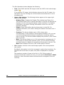
Journal Operation Window ................................................................................ 4-2
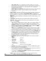
Pair Operation Window ..................................................................................... 4-7
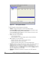
DKC Operation Window................................................................................... 4-13
Displaying Information about Remote Storage Systems............................... 4-15
Displaying Information about Logical Paths ................................................ 4-17
Displaying Information about Ports on the Local Storage System ................. 4-18
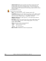
Usage Monitor Window ................................................................................... 4-20
History Window .............................................................................................. 4-21
Optional Operation Window............................................................................. 4-27
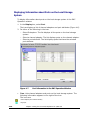
EXCTG Operation Window ............................................................................... 4-29
Displaying a List of Extended Consistency Groups....................................... 4-32
Displaying a List of Storage Systems in an Extended Consistency Group ....... 4-34
Displaying a List of Journal Groups in an Extended Consistency Group ......... 4-35
Configuring Storage Systems and Logical Paths ...................................... 5-1
Reviewing Storage System and Logical Paths ...................................................... 5-2
Setup Procedure for Multiple Primary and Secondary Storage Systems ........... 5-3
Setup Procedure (When More Than One Primary and Secondary Storage
System are Used) ................................................................................ 5-4
Configuring Port Attributes ................................................................................ 5-5
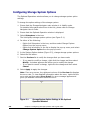
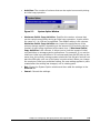
Configuring Storage System Options .................................................................. 5-8
Establishing the Relationship between Primary and Secondary Storage
Systems (Add DKC).................................................................................. 5-10
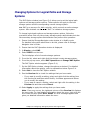
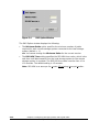
Changing Options for Logical Paths and Storage Systems .................................. 5-13
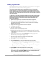
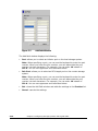
Adding Logical Paths....................................................................................... 5-15
Viewing the Status of Logical Paths.................................................................. 5-17
Deleting Logical Paths..................................................................................... 5-20
Managing SIMs............................................................................................... 5-21
Enabling or Disabling SIM Reporting .......................................................... 5-21
Clearing Service Information Messages (SIMs) ........................................... 5-22
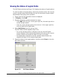
Managing Power for Storage Systems and Network Relay Devices ...................... 5-23
When Power Stops Unexpectedly .............................................................. 5-23
When the Power is Removed from the Primary Storage System............. 5-23
When the Power is Removed from the Secondary Storage System......... 5-23
viii
Contents
Hitachi Universal Replicator for IBM /OS User’s Guide
When the Power is Removed from Network Relay Devices.....................5-24
Turning Off Power Intentionally .................................................................5-24
When You Power Off the Primary Storage System.................................5-24
When You Power Off the Secondary Storage System.............................5-25
When You Power Off the Primary and Secondary Storage Systems
at the Same Time ........................................................................5-26
When You Power Off Network Relay Devices ........................................5-27
Removing the Relationship Between the Primary and the Secondary
Storage Systems.......................................................................................5-28
Configuring Journal Groups ................................................................... 6-1
Reviewing Administrator Tasks for Managing Journals ..........................................6-2
Registering Journal Volumes in a Journal Group...................................................6-3
Deleting Journal Volumes from a Journal Group...................................................6-9
Displaying Detailed Information about a Journal Group ......................................6-11
Changing Options for a Journal Group...............................................................6-16
Deleting a Journal Group .................................................................................6-21
Splitting a Mirror (Suspending a copy operation)................................................6-22
Restoring a Mirror (Resuming a copy operation) ................................................6-24
Deleting Data Volumes from a Mirror (Ending a copy operation)..........................6-26
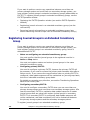
Using Extended Consistency Groups....................................................... 7-1
Registering Journal Groups in an Extended Consistency Group..............................7-2
Manipulating Data Volume Pairs in Extended Consistency Groups ..........................7-5
Removing Journal Groups from an Extended Consistency Group ...........................7-7
Forcibly Removing Journal Groups from an Extended Consistency Group ...............7-9
Performing Pair Operations ................................................................... 8-1
Filtering Information in the List in the Pair Operation Window...............................8-2
Creating a Pair of Data Volumes .........................................................................8-5
Displaying Detailed Information about a Pair of Data Volumes ............................8-11
Saving Pair Status Information into a Text File...................................................8-16
Changing Options for a Data Volume Pair..........................................................8-18
Splitting a Pair of Data Volumes .......................................................................8-20
Restoring a Pair of Data Volumes .....................................................................8-23
Releasing a Pair of Data Volumes .....................................................................8-26
Recovering a Pinned Track...............................................................................8-28
Recovering a Pinned Track on a Data Volume .............................................8-28
Recovering a Pinned Track on a Journal Volume..........................................8-29
Usage Monitor Operations ..................................................................... 9-1
Reviewing the Usage Monitor Window ................................................................9-2
Starting and Stopping Usage Monitoring ............................................................. 9-3
Displaying the Usage Monitor Graph................................................................... 9-4
Saving Monitoring Data in Text Files .................................................................. 9-7
Saving Operation History into a Text File ............................................................ 9-8
Usage Scenarios..................................................................................10-1
Creating a Point-in-Time Copy of Data Volumes ................................................ 10-2
Performing Disaster Recovery Operations ......................................................... 10-2
Preparing for Disaster Recovery Operations................................................ 10-2
File and Database Recovery Procedures ..................................................... 10-3
Switching Operations to the Secondary Site ............................................... 10-4
Transferring Operations Back to the Primary Site........................................ 10-5
Resuming Normal Operations at the Primary Site........................................ 10-6
Disaster Recovery for Multiple Primary and Secondary Storage Systems ....... 10-7
Consistency of Data Update Sequence When a Disaster Occurs............. 10-7
Disaster Recovery Procedure .............................................................. 10-8
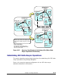
Disaster Recovery in a 3DC Cascading Configuration................................... 10-9
Recovering from a Disaster at the Main Site in a 3DC Multi-Target
Configuration .................................................................................... 10-9
Recovering from Failures in the Primary Site (When Delta
Resync Operation is Performed) ..................................................10-11
Establishing 3DC Delta Resync Operations .......................................................10-13
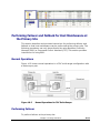
Performing Failover and Failback for Host Maintenance at the Primary Site.........10-17
Normal Operations ..................................................................................10-17
Performing Failover .................................................................................10-17
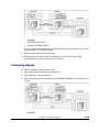
Performing Failback ................................................................................10-19
Troubleshooting ...................................................................................... 1
Troubleshooting .................................................................................................. 2
General Troubleshooting ...................................................................................... 2
Universal Replicator for z/OS® Software Error Codes .............................................. 7
Checking Service Information Messages (SIMs)...................................................... 8
Calling the Hitachi Data Systems Support Center.................................................. 11
Acronyms and Abbreviations .......................... Acronyms and Abbreviations-1
Index ............................................................................................ Index-1
x
Contents
Hitachi Universal Replicator for IBM /OS User’s Guide
Preface
This document describes and provides instructions for using the Universal
Replicator for z/OS® software to configure and perform operations on the
Hitachi Universal Storage Platform V (USP V) storage system.
Please read this document carefully to understand how to use this product,
and maintain a copy for reference purposes.
This preface includes the following information:
Intended Audience
Product Version
Document Revision Level
Changes in this Revision
Document Organization
Referenced Documents
Document Conventions
Convention for Storage Capacity Values
Getting Help
Comments
Notice: The use of Universal Replicator for z/OS® and all other Hitachi Data
Systems products is governed by the terms of your agreement(s) with Hitachi
Data Systems.
Preface
Hitachi Universal Replicator for IBM /OS User’s Guide
xi
Intended Audience
This document is intended for system administrators, Hitachi Data Systems
representatives, and Authorized Service Providers who are involved in
installing, configuring, and operating the Hitachi Universal Storage Platform V
storage system.
This document assumes the following:
•
The user has a background in data processing and understands RAID
storage systems and their basic functions.
•
The user is familiar with the Hitachi Universal Storage Platform V storage
system and has read the Universal Storage Platform V User and Reference
Guide.
•
The user is familiar with the Storage Navigator software for the Universal
Storage Platform V and has read the Storage Navigator User’s Guide.
•
The user is familiar with the operating system and web browser software
on the system hosting the Storage Navigator software.
Product Version
This document revision applies to Universal Storage Platform V microcode 6001-3x and higher.
Document Revision Level
Revision
Date
Description
MK-96RD625-P
February 2007
Preliminary Release
MK-96RD625-00
April 2007
Initial Release, supersedes and replaces MK-96RD625-P
MK-96RD625-01
May 2007
Revision 1, supersedes and replaces MK-96RD625-00
Changes in this Revision
Not applicable to this release.
xii
Preface
Hitachi Universal Replicator for IBM /OS User’s Guide
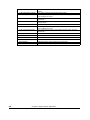
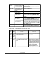
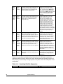
Document Organization
The following table provides an overview of the contents and organization of
this document. Click the chapter title in the left column to go to that chapter.
The first page of each chapter provides links to the sections in that chapter.
Chapter
Description
Chapter_1_Overview_of_Univers
al_Replicator_for_IBM_z/OS®
This chapter provides an overview of the Hitachi Universal Replicator software
and describes its features and benefits.
Chapter_2_About_Universal_Repl
icator_Ope
This chapter provides an overview of Universal Replicator operations.
Chapter_3_Preparing_for_Univer
sal_Replic
This chapter describes URz operations involving the USP V primary and
secondary storage systems, the remote copy connections between the primary
\secondary storage systems, and the host(s) at the primary and secondary sites,
as well as the licensed URz remote console software
Chapter_4_Using_the_Universal_
Replicator
This chapter how to use the Universal Replicator for z/OS graphical user
interface.
Chapter_5_Configuring_Storage_
Systems_an
This chapter how to use the Universal Replicator for z/OS graphical user
interface.
Chapter_6_Configuring_Journal_
Groups
This chapter describes the introduction of the URz in your system and explains
how to configure your system for remote copy operations.
Chapter_7_Using_Extended_Con
sistency_Gro
This chapter explains how to perform remote copy operations between more
than one primary and secondary storage system, as well as how to register
journal groups in extended consistency groups (abbreviated as EXCTG).
Chapter_8_Performing_Pair_Ope
rations
This chapter explains how to perform remote copy operations with URz, including
how to create pairs of a primary data volume and a secondary data volume.
Chapter_9_Usage_Monitor_Oper
ations
This chapter describes the Usage Monitoring window which enables you to collect
I/O statistics for all volumes to be monitored on the connected storage system.
Chapter_10_Usage_Scenarios
This chapter describes how to use URz to enables to make Point-in-Time (PiT)
duplicates of groups of volumes.
Troubleshooting
This chapter provides troubleshooting information for Universal Replicator for
z/OS® and instructions for calling technical support.
Acronyms and Abbreviations
Defines the acronyms and abbreviations used in this document.
Index
Lists the topics in this document in alphabetical order.
Referenced Documents
Hitachi Universal Storage Platform V:
•
LUN Manager User’s Guide, MK-96RD615
•
User and Reference Guide, MK-96RD635
•
Storage Navigator User’s Guide, MK-96RD621
•
Business Continuity Manager User and Reference Guide, MK-94RD247
•
Data Retention Utility User's Guide, MK-94RD210
•
Virtual LVI/LUN and Volume Shredder User's Guide, MK-96RD630
Preface
Hitachi Universal Replicator for IBM /OS User’s Guide
xiii
•
Universal Volume Manager User's Guide, MK-94RD626
•
Guideline for the Timeout Menu Setting When Using At-Time Split Function
at Combining Universal Replicator with ShadowImage
•
TrueCopy for IBM z/OS User's Guide, MK-94RD623
Document Conventions
The terms “Universal Storage Platform V” and “USP V” refer to all models of
the Hitachi Universal Storage Platform V, unless otherwise noted.
This document uses the following typographic conventions:
Typographic Convention
Description
Bold
Indicates text on a window, other than the window title, including menus, menu
options, buttons, fields, and labels. Example: Click OK.
Italic
Indicates a variable, which is a placeholder for actual text provided by the user or
system. Example: copy source-file target-file
Note: Angled brackets (< >) are also used to indicate variables.
Indicates text that is displayed on screen or entered by the user. Example: #
screen/code
pairdisplay -g oradb
< > angled brackets
Indicates a variable, which is a placeholder for actual text provided by the user or
system. Example: # pairdisplay -g <group>
Note: Italic font is also used to indicate variables.
[ ] square brackets
Indicates optional values. Example: [ a | b ] indicates that you can choose a, b, or
nothing.
{ } braces
Indicates required or expected values. Example: { a | b } indicates that you must
choose either a or b.
| vertical bar
Indicates that you have a choice between two or more options or arguments.
Examples:
[ a | b ] indicates that you can choose a, b, or nothing.
{ a | b } indicates that you must choose either a or b.
underline
Indicates the default value. Example: [ a | b ]
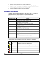
This document uses the following icons to draw attention to information:
Icon
xiv
Meaning
Description
Note
Calls attention to important and/or additional information.
Tip
Provides helpful information, guidelines, or suggestions for performing tasks more
effectively.
Caution
Warns the user of adverse conditions and/or consequences (e.g., disruptive
operations).
WARNING
Warns the user of severe conditions and/or consequences (e.g., destructive
operations).
DANGER
Dangers provide information about how to avoid physical injury to yourself and
others.
Preface
Hitachi Universal Replicator for IBM /OS User’s Guide
ELECTRIC SHOCK
HAZARD!
Warns the user of electric shock hazard. Failure to take appropriate precautions
(e.g., do not touch) could result in serious injury.
ESD Sensitive
Warns the user that the hardware is sensitive to electrostatic discharge (ESD).
Failure to take appropriate precautions (e.g., grounded wriststrap) could result in
damage to the hardware.
Convention for Storage Capacity Values
Physical storage capacity values (e.g., disk drive capacity) are calculated
based on the following values:
1
1
1
1
1
KB = 1,000 bytes
MB = 1,0002 bytes
GB = 1,0003 bytes
TB = 1,0004 bytes
PB = 1,0005 bytes
Logical storage capacity values (e.g., logical device capacity) are calculated
based on the following values:
1
1
1
1
1
1
KB = 1,024 bytes
MB = 1,0242 bytes
GB = 1,0243 bytes
TB = 1,0244 bytes
PB = 1,0245 bytes
block = 512 bytes
Getting Help
If you need to call the Hitachi Data Systems Support Center, make sure to
provide as much information about the problem as possible, including:
•
The circumstances surrounding the error or failure.
•
The exact content of any error messages displayed on the host system(s).
•
The exact content of any error messages displayed by Storage Navigator.
•
The Storage Navigator configuration information (use the FD Dump Tool).
•
The service information messages (SIMs), including reference codes and
severity levels, displayed by Storage Navigator.
The Hitachi Data Systems customer support staff is available 24 hours/day,
seven days a week. If you need technical support, please call:
•
United States: (800) 446-0744
•
Outside the United States: (858) 547-4526
Preface
Hitachi Universal Replicator for IBM /OS User’s Guide
xv
Comments
Please send us your comments on this document. Make sure to include the
document title, number, and revision. Please refer to specific section(s) and
paragraph(s) whenever possible.
•
E-mail: [email protected]
•
Fax: 858-695-1186
•
Mail:
Technical Writing, M/S 35-10
Hitachi Data Systems
10277 Scripps Ranch Blvd.
San Diego, CA 92131
Thank you! (All comments become the property of Hitachi Data Systems
Corporation.)
xvi
Preface
Hitachi Universal Replicator for IBM /OS User’s Guide
1
Overview of Universal Replicator for
IBM z/OS®
This chapter provides an overview of the Hitachi Universal Replicator software
and describes its features and benefits. This chapter covers the following key
topics:
Hitachi Universal Replicator
Features
Benefits
Chapter 2 About Universal Replicator Operations
Hitachi Universal Replicator for IBM /OS User’s Guide
1-1
Hitachi Universal Replicator
The Hitachi Universal Replicator software intelligently replicates data among
storage environments controlled through the Hitachi Universal Storage
Platform V, satisfying the most demanding disaster recovery and uptime
requirements. Since its introduction on the Hitachi TagmaStore® Universal
Storage Platform and Network Storage Controller, the Universal Replicator
software has set a new standard for data protection by redefining the way
asynchronous replication is performed.
Reliable data storage and recovery systems are essential in today’s market
climate where downtime can be very costly. Businesses must manage
increasing amounts of data across a variety of storage systems and operating
environments in various locations, while optimizing usage of storage hardware
resources and minimizing the management burden.
To address these needs, Hitachi Universal Replicator software provides the
enterprise-class performance associated with storage system-based replication
while delivering resilient business continuity. Through the Hitachi RAID storage
systems, Universal Replicator provides a powerful data management and
recovery solution that replicates data to a variety of storage platforms at one
or multiple remote sites. Data is replicated asynchronously over any distance
without the need for redundant servers or replication appliances, thus
significantly reducing resource consumption.
The Hitachi Universal Replicator software helps organizations to:
1-2
•
Lower the cache and resource consumption on production/primary storage
systems
•
Improve bandwidth utilization
•
Simplify bandwidth planning
•
Mitigate the impact of network failures
•
Gain more flexibility in trading off between Recovery Point Objective and
cost
•
Implement advanced multi–data center support more easily
•
Move data among levels of tiered storage systems more easily
•
Fully leverage the Universal Storage Platform V and optimize the storage
infrastructure
Chapter 3 Preparing for Universal Replicator z/OS Operations
Hitachi Universal Replicator for IBM /OS User’s Guide
Features
Hitachi Universal Replicator provides the following key features:
•
•
Heterogeneous Storage System Support
–
Used with the Universal Storage Platform or Network Storage
Controller, Universal Replicator software enables storage management
and disaster recovery in heterogeneous systems, providing maximum
flexibility and support of enterprise-class environments.
–
Universal Replicator software supports any storage connected to a
Universal Storage Platform or Network Storage Controller, permitting
data to be copied from any supported device to any other supported
device, regardless of operating system or protocol differences. This
ensures maximum flexibility for data distribution as well as increased
storage utilization and failover options.
More Efficient Replication
–
Universal Replicator software uses asynchronous replication driven by
the remote site to minimize impact on primary production systems and
takes advantage of journaling rather than cache files to mitigate the
high resource usage of other asynchronous approaches.
–
Storage usage on the Universal Storage Platform or Network Storage
Controller can be minimal, just enough for the journals.
–
Limited use of cache leaves cache for production application usage,
further restoring primary site storage to its intended role as a
transaction processing resource, not a replication engine.
–
Advanced three data center capabilities provide a choice of cascade or
multi-target configurations (teams with TrueCopy Synchronous software
for advanced configurations).
–
Consistency groups can span multiple storage systems for large
enterprise-class applications requiring unmatched scalability and data
integrity.
Note: Please check with your Hitachi Data Systems representative for detailed
feature availability information.
Chapter 2 About Universal Replicator Operations
Hitachi Universal Replicator for IBM /OS User’s Guide
1-3
Benefits
The business benefits of Hitachi Universal Replicator include:
•
•
•
•
1-4
Ensure Business Continuity
–
Simplifies implementation to meet the most demanding disaster
recovery and uptime requirements, regardless of the type of supported
storage platform hosting the business-critical data
–
Supports availability of up-to-date copies of data in dispersed locations
by leveraging Hitachi TrueCopy® Synchronous software
–
Maintains integrity of a replicated copy without impacting processing,
even when replication network outages occur or optimal bandwidth is
not available
–
Works with Universal Storage Platform V replication technology to
greatly enhance administrative productivity and response to and
proactive aversion of crises
Optimize Resource Usage
–
Leverages advanced technology to maintain data integrity and optimize
the storage/IT infrastructure for protection of data from any application
across a variety of hardware and software platforms
–
Optimizes storage resources for more efficient data protection over any
distance
–
Significantly reduces cache utilization and increases bandwidth
utilization by leveraging performance-optimized disk-based journals
–
Reduces overhead and application impact at production site by placing
more of the workload on remote site
–
Centralizes operations for management resources and provides secure
management of data-related operational risk
Improve Operational Efficiency and Resiliency
–
Simplifies consolidation/aggregation and mapping of data value to the
cost of storage
–
Supports planned site outages
–
Keeps logging changes in the event of network problems between sites
–
Reduces costs—requires only one product to provide asynchronous copy
across all attached storage systems
Synergy with Hitachi Business Continuity Framework
–
Builds on the data integrity heritage of Hitachi open-systems and
mainframe remote replication software
–
Provides unified, simplified management via Hitachi HiCommand®
Device Manager and Hitachi Business Continuity Manager software for
IBM® z/OS®
Chapter 3 Preparing for Universal Replicator z/OS Operations
Hitachi Universal Replicator for IBM /OS User’s Guide
–
Integrates tightly with other Hitachi software products supporting
business continuity, further expanding capabilities
Business Solutions
Hitachi Data Systems and its Hitachi TrueNorth™ Channel Partners provide
cost-effective storage products and solutions that leverage world-renowned
Hitachi global R&D resources to deliver performance, availability, and
scalability—supporting business-critical applications and strengthening
competitive advantage.
Complementary solutions for Universal Replicator software include:
•
Hitachi HiCommand® Replication Monitor software
•
Hitachi TrueCopy® Synchronous software, which duplicates data between
like Hitachi storage systems
•
Hitachi ShadowImage™ Heterogeneous In-System Replication software for
non-disruptive, high-speed data replication within any Hitachi storage
system
Hitachi Business Continuity Manager software for managing TrueCopy and
ShadowImage solutions for IBM® z/OS® mainframe
Chapter 2 About Universal Replicator Operations
Hitachi Universal Replicator for IBM /OS User’s Guide
1-5
1-6
Chapter 3 Preparing for Universal Replicator z/OS Operations
Hitachi Universal Replicator for IBM /OS User’s Guide
2
About Universal Replicator Operations
This chapter provides an overview of Universal Replicator operations:
Functionality Overview
Components
Remote Copy Operations
Journal Processing
URz Delta Resync Operation
Pair Status
Business Continuity Manager Support
Chapter 3 Preparing for Universal Replicator z/OS Operations
Hitachi Universal Replicator for z/OS User’s Guide
2-1
Functionality Overview
Hitachi Universal Replicator represents a unique and outstanding disaster
recovery solution for large amounts of data that span multiple volumes. The
UR group-based update sequence consistency solution enables fast and
accurate database recovery, even after a “rolling” disaster, without the need
for time-consuming data recovery procedures. The user-defined UR journal
groups (volume groups) at the secondary site can be recovered with full
update sequence consistency but behind the primary site due to asynchronous
copy operations. This functionality also provides protection for writedependent applications in the event of a disaster.
UR enables you to create duplicate volumes by copying data from the primary
data volumes in the primary storage system to the secondary data volumes in
the secondary storage system at the remote location. To perform this function,
the journal obtain function at the primary site, the journal copy function
between the primary and secondary sites, and the journal restore function at
the secondary site are performed sequentially with the primary and secondary
data volumes and the journal volumes. Write sequence consistency for the
primary data volume at the primary site is also maintained for the secondary
data volume at the secondary site by the write sequence number to be
assigned for the journal data with the journal obtaining function, enabling you
to configure the duplicate system which has data integrity. UR reduces the
occurrence of pair suspensions due to restrictions of data transfer from the
primary site to the secondary site by storing the write data from the host in
the master and restore journal volumes, providing a high-reliability duplication
system.
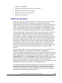
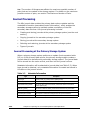
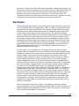
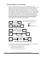
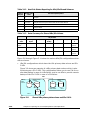
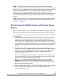
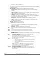
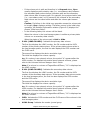
Figure 2-1 UR Components for Fibre-Channel Connection shows an overview of
UR operations.
2-2
Chapter 3 Preparing for Universal Replicator z/OS Operations
Hitachi Universal Replicator for IBM /OS User’s Guide
Primary site
Secondary site
Primary host
Secondary host
Write instruction
Issuing Read
Journal command
Primary
data
volume
Journal obtain
function
Master
journal
volume
Primary storage system
Journal copy function
Secondary
data
volume
Restore
journal
volume
Journal restore
function
Secondary storage system
Figure 2-1 UR Components for Fibre-Channel Connection
Journal Obtain
Journal obtain is the function to store the already stored data in the primary
data volume as a base-journal in the journal volume at the primary site. And
then, this function stores the write data as a journal data in the journal
volume with every update of the primary data volume according to the write
instruction from the host. The journal obtain operation is performed according
to the instruction of add pair or Resume Pair operation from the primary site.
The write sequence number from the host is assigned to the journal data.
According to this information, the write sequence consistency at the secondary
site can be maintained. The update data from the host is kept in the cache.
Therefore, the journal obtain function for the update data is performed
asynchronously from the time the storage system receives the update data
from the host and stores the update data to the data volume.
Chapter 2 About Universal Replicator Operations
Hitachi Universal Replicator for IBM /OS User’s Guide
2-3
Journal Copy
Journal copy is the function to copy the data in the master journal volume at
the primary site to the restore journal volume at the secondary site. The
secondary storage system issues the read journal command to the primary
storage system to request to transfer the data that is stored in the master
journal volume according to the pair create or Resume Pair operation
instruction from the primary site. The primary storage system transfers the
data in the journal volume to the secondary site according to the read journal
command if it has the journal data that should be sent. If the primary storage
system does not have the journal data, the information is sent. The secondary
storage system stores the journal volume data that is sent from the primary
site in the restore journal volume at the secondary site. The read journal
commands are issued repeatedly and regularly from the secondary site to the
primary site until the journal operation is stopped. After the data are restored,
the journal sequence numbers are informed from the secondary site to the
primary site when the read journal command is issued. According to this
information, the journal data at the primary site are discarded.
Journal Restore
Journal restore is the function to reflect the stored data in the restore journal
volume to the secondary data volume at the secondary site. The data in the
restore journal volume are restored to the secondary data volume according to
the write sequence number. This will ensure the write sequence consistency
between the primary and secondary data volumes. After the journal data are
restored to the secondary data volume, the journal data are discarded at the
secondary site.
Components
URz operations involve the USP V storage systems at the primary and
secondary sites, the physical communications paths between these storage
systems, and the USP V URz remote console software. URz copies the original
online data at the primary site to the offline backup volumes at the secondary
site via the dedicated fibre-channel remote copy connections using a journal
volume. You can operate the URz software with the user-friendly GUI
environment using the USP V URz remote console software.
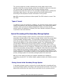
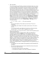
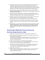
Note: Host failover software is required for effective disaster recovery with URz.
For management of URz journal groups that consist of journal volumes located
in multiple storage systems, host I/O time stamping function (provided by
MVS DFSMSdfp) is a requisite functional item. An error reporting
communications (ERC) feature is essential for URz to be able to recover data
lost in a disaster.
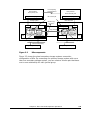
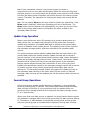
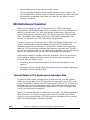
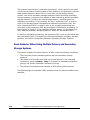
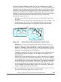
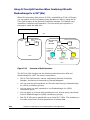
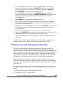
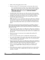
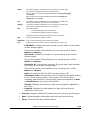
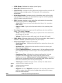
Figure 2-2 shows the URz components and their functions:
2-4
Chapter 3 Preparing for Universal Replicator z/OS Operations
Hitachi Universal Replicator for IBM /OS User’s Guide
Error Reporting
Communications
Host processor
at the primary site
(MVS) Time stamping function
Storage system
Primary subsystem (LDKC)
CHT
MCU
Host processor
at the secondary site
URz volume pair
Remote copy
connection
Initiator port
(MVS) Time stamping function
Disk subsystem
Storage system (LDKC)
RCU target port
RCU
CHT
Copy direction
Primary
data
volume
SVP
Master
journal
volume
RCU target port
Secondary
Ldata
volume
Restore
journal
volume
SVP
Initiator port
Restore journal group
Master journal group
Internal LAN (TCP/IP)
Storage Navigator computer
Figure 2-2
Storage Navigator computer
URz components
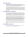
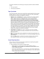
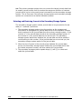
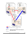
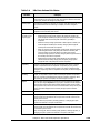
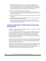
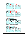
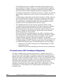
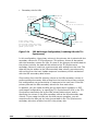
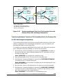
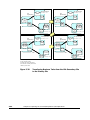
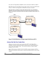
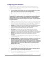
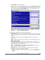
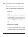
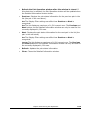
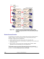
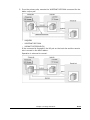
Figure 2-3 shows the plural secondary storage systems connection
configuration of URz. By connecting one primary storage system with more
than one secondary storage system, you can create a volume pair that has a
one-to-one relationship for each journal group.
Chapter 2 About Universal Replicator Operations
Hitachi Universal Replicator for IBM /OS User’s Guide
2-5
Primary storage system
Primary
data
volume
Master
journal
volume
Secondary storage system
Secondary
Ldata
volume
Restore
journal
volume
Master journal group 0
Secondary storage system
Primary
data
volume
Master
journal
volume
Secondary
Ldata
volume
Restore
journal
volume
Master journal group 1
Secondary storage system
Primary
data
volume
Master
journal
volume
Secondary
Ldata
volume
Restore
journal
volume
Master journal group n
Figure 2-3
Connection Configuration of Plural Secondary Storage
systems
This URz components describes:
2-6
•
USP V storage system
•
Logical DKC
•
Main and remote control units (primary storage systems and secondary
storage systems)
•
Journal group
•
Data volume pair
•
Journal volume
•
Remote copy connections
•
Initiator ports and RCU target ports
•
USP V URz remote console software
•
Host I/O time stamping function
•
Error reporting communications (ERC)
Chapter 3 Preparing for Universal Replicator z/OS Operations
Hitachi Universal Replicator for IBM /OS User’s Guide
USP V Storage Systems
URz operations involve the USP V storage systems at the primary and
secondary sites. The primary storage system consists of the main control unit
(primary storage system) and SVP. The secondary storage system consists of
the remote control unit (secondary storage system) and SVP.
To provide greater flexibility and to enable the USP V to be tailored to unique
customer operating requirements, operational parameters, or optional modes,
are available in URz for the USP V storage system. At installation, the USP V
modes are set to their default values, so make sure to discuss these settings
with your Hitachi team. The USP V modes can only be changed by your Hitachi
representative.
Universal Replicator for z/OS® Software
USP V Storage Navigator Java applet program product includes URz for the
USP V storage system. The USP V Storage Navigator software communicates
with the SVP of each USP V storage system via defined TCP/IP connections.
For further information on USP V Storage Navigator operations, please refer to
the Storage Navigator User's Guide, or contact your Hitachi account team.
The Storage Navigator PC at the primary site must be attached to the primary
storage system. You should also attach a Storage Navigator PC at the
secondary site to all secondary storage systems. Having a Storage Navigator
PC at the secondary site enables you to change the URz parameter of the
secondary storage system and access the URz secondary data volume (e.g. for
the maintenance of media). If you need to perform URz operations in the
reverse direction from the secondary site to the primary site (e.g., disaster
recovery), the USP V URz software simplifies and expedites this process.
Note: If the USP V Storage Navigator remote console PC is not installed, please
contact your Hitachi account team for information on URz configuration
services.
Main and Remote Control Units
The main control unit (primary storage system) and remote control unit
(secondary storage system) control URz operations:
Chapter 2 About Universal Replicator Operations
Hitachi Universal Replicator for IBM /OS User’s Guide
2-7
•
The primary storage system is the control unit in the primary storage
system which controls the primary data volume of the URz pairs and
master journal volume. The Storage Navigator remote console PC must be
LAN-attached to the primary storage system. The primary storage system
communicates with the secondary storage system via the dedicated remote
copy connections. The primary storage system controls the host I/O
operations to the URz primary data volume and the journal obtain
operation of the master journal volume as well as the URz initial copy and
update copy operations between the primary data volumes and the
secondary data volumes.
•
The secondary storage system is the control unit in the secondary storage
system which controls the secondary data volume of the URz pairs and
restore journal volume. The secondary storage system controls copying of
journals and restoring of journals to secondary data volumes. The
secondary storage system assists in managing the URz pair status and
configuration (e.g., rejects write I/Os to the URz secondary data volumes).
The secondary storage system issues the read journal command to the
primary storage system and executes copying of journals. The secondary
Storage Navigator PC should be connected to the secondary storage
systems at the secondary site on a separate LAN. The secondary storage
systems should also be attached to a host system to allow sense
information to be reported in case of a problem with a secondary data
volume or secondary storage system and to provide disaster recovery
capabilities.
The USP V can function simultaneously as a primary storage system for one or
more primary data volumes and as a secondary storage system for one or
more secondary data volumes, provided the remote copy connections and
fibre-channel interface ports are properly configured. The URz software allows
you to specify the secondary storage system from the connected primary
storage system. URz operations can be performed on all LDEVs except for the
USP V command device. For further information on the USP V command
device, please refer to the Business Continuity Manager User and Reference
Guide.
Note: When you configure a URz journal group pair, you have to specify the
serial numbers of primary storage systems and secondary storage systems.
You have to specify the different serial numbers of primary storage system
and secondary storage system for the same URz journal group pair. If you
have to specify the same serial number, please contact your Hitachi account
team.
Logical DKC (LDKC)
The USP V storage system controls the CU (Control Unit) by dividing the CUs
in to groups of 255 CUs. Each group is a storage system that logically exists in
USP V (logical storage system). These groups are called a “logical DKC” or an
“LDKC (Logical disk controller)”. There are 2 LDKCs in the USP V storage
system and number “00” and “01” is assigned to each LDKC.
2-8
Chapter 3 Preparing for Universal Replicator z/OS Operations
Hitachi Universal Replicator for IBM /OS User’s Guide
Each LDKC controls 255 CUs, however the number of CUs that can be used for
USP V program products is up to 255. Therefore, the maximum number of
volumes that can be used for USP V program products is 130,560 (65,280
volumes for an LDKC).
Remote Copy Connections
The remote copy connections are the physical paths used by the primary
storage systems to communicate with the secondary storage systems. Remote
copy connections enable communication between the primary and secondary
storage systems. The primary storage systems and secondary storage systems
are connected via fibre-channel interface cables. You must establish paths
from the primary to the secondary storage system, and also from the
secondary to the primary storage system. Up to eight paths can be established
in both of these directions.
When fibre-channel interface (optical multimode shortwave) connections are
used, two switches are required for distances greater than 0.5 km (1,640
feet), and distances up to 1.5 km (4,920 feet, 0.93 miles) are supported. If
the distance between the primary and secondary sites is greater than 1.5 km,
the optical single mode long wave interface connections are required. When
fibre-channel interface (single-mode long wave) connections are used, two
switches are required for distances greater than 10 km (6.2 miles), and
distances up to 30 km (18.6 miles) are supported.
See section Setting up Remote Copy Connections for further information on
installing and configuring the FC remote copy connections.
The URz remote copy configuration between primary storage system and
secondary storage system has the following requirements:
URz supports 1-to-1 remote copy connection in one journal group pair. In
one journal group pair, one primary storage system can be connected to
only one secondary storage system. This configuration ensures the backup
data consistency of two or more volumes (e.g., large databases) within the
same storage system.
Note: Hitachi strongly recommends that you establish at least two independent
remote copy connections from the primary storage system to the secondary
storage system and vice versa to provide hardware redundancy for this critical
communications path.
Chapter 2 About Universal Replicator Operations
Hitachi Universal Replicator for IBM /OS User’s Guide
2-9
Initiator Ports and RCU Target Ports
The initiator port and the RCU target port are required at both the primary
storage system and secondary storage system. The initiator port at the
primary storage system is connected to the RCU target port at the secondary
storage system via the fibre channel interface. The initiator port at the
secondary storage system is connected to the RCU target port at the primary
storage system. The initiator port at the secondary storage system issues a
"read journal" command to the primary storage system, and then the RCU
target port at the primary storage system sends journal data to the secondary
storage system in response to the "read journal" command.
Any fibre-channel interface port of the USP V can be configured as an initiator
port. The initiator ports cannot communicate with the host processor channels.
The host channel paths must be connected to the fibre-channel interface port
other than the initiator port.
Note: Two or more initiator ports must be configured before you can add the
secondary storage systems and create the URz volume pairs.
The fibre-channel interface ports that are assigned for the RCU target ports
can be connected to the host channel paths via the fibre-channel switch.
See section Configuring Port Attributes for the information on configuring host
interface port.
Data Volume Pair
URz performs remote copy operations for data volume pairs created by the
user. Each URz pair consists of one primary data volume and one secondary
data volume which can be located in different storage systems. The URz
primary data volumes are the primary volumes (LDEVs) which contain the
original data, and the URz secondary data volumes are the secondary volumes
(LDEVs) which contain the backup or duplicate data. During normal URz
operations, the primary data volume remains available to all hosts at all times
for read and write I/O operations. During normal URz operations, the
secondary storage system rejects all host-requested write I/Os for the
secondary data volume. The secondary data volume write enable option allows
write access to a secondary data volume while the pair is split and uses the
secondary data volume and primary data volume track maps to resynchronize
the pair (see section Secondary Data Volume Write Option).
URz also supports the Virtual LVI/LUN (VLL) and Cache Residency Manager
features, so that URz meets a variety of user needs and facilitates data
copying and data migration. This ensures that all user data can be backed up
or duplicated. See section Duplicate VOLSER (Volume Serial Number) for
further information on LU requirements and support.
2-10
Chapter 3 Preparing for Universal Replicator z/OS Operations
Hitachi Universal Replicator for IBM /OS User’s Guide
Journal Volume
When URz is used, updates to primary data volumes can be stored in other
volumes, which are called journal volumes. The updates (which are sometimes
referred to as update data) that will be stored in journal volumes are called
journal data.
Because journal data will be stored in journal volumes, you can perform and
manage highly reliable remote copy operations without suspension of remote
copy operations. For example:
Even if a communication path between the primary storage system and the
secondary storage system fails temporarily, remote copy operations can
continue after the communication path is recovered.
If data transfer from hosts to the primary storage system is temporarily faster
than data transfer between the primary storage system and the secondary
storage system, remote copy operations between the primary storage system
and the secondary storage system can continue. Because journal volumes can
contain a lot more update data than the cache memory can contain, remote
copy operations can continue if data transfer from hosts to the primary
storage system is faster for a relatively long period of time than data transfer
between the primary storage system and the secondary storage system.
The Number of Journal Volumes
One journal group can contain up to 64 journal volumes. Each of the journal
volumes can have different volume sizes and different RAID configurations.
Journal data will be stored sequentially and separately into each journal
volume in the same journal group.
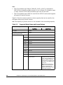
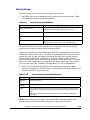
Specifications of Journal Volumes
Types of logical units (LUs):
The following DKU emulation types are allowed for journal volumes:
Table 2-1
Emulation Types for Journal Volumes
Emulation Category
DKU (drive)
Supported Emulation Types
OPEN-V
All mainframe volumes that can be used with USP V
Note: Status of mainframe volumes cannot be referenced.
Volumes and their capacity:
You can use VLL volumes for journal volumes.
Journal volumes in the same journal group can be of different capacity. A
master journal volume and the corresponding restore journal volume can
be of different capacity.
Chapter 2 About Universal Replicator Operations
Hitachi Universal Replicator for IBM /OS User’s Guide
2-11
A journal volume consists of two areas: one area is used for storing journal
data, and the other area is used for storing metadata for remote copy.
RAID configuration:
Journal volumes support all RAID configurations that are supported by
USP V. Journal volumes also support all physical volumes that are
supported by USP V.
Support for program products:
The volumes on which Cache Residency Manager settings are made can be
used for journal volumes.
Caution: Volumes containing a VMA (volume management area) cannot be used
as journal volumes. For detailed information about a VMA, please refer to the
Data Retention Utility User's Guide.
Restrictions on Journal Volumes
Registering journal volumes:
Caution: You must register journal volumes in a journal group before you
create a data volume pair for the first time in the journal group.
You can add journal volumes under any of the following conditions:
–
When the journal group does not contain data volumes (i.e., before you
create a data volume pair for the first time in the journal group, or after
all data volume pairs are released)
–
When all data volume pairs in the journal group are suspended.
–
When processing for changing the status of a data volume pair (for
example, release or suspension of a data volume pair) is not in progress
Note: If a path is defined from a host to a volume, you cannot register the
volume as a journal volume.
You can use Storage Navigator computers to register journal volumes.
If you add a journal volume when a remote copy operation is in progress
(i.e., when at least one data volume pair exists for data copying), the
metadata area of the journal volume (see the next section) will be unused
and only the journal data area will be used. To make the metadata area
usable, you need to split (suspend) all the data volume pairs in the journal
group and then restore (resynchronize) the pairs.
Adding journal volumes during a remote copy operation will not decrease
the metadata usage rate if the metadata usage rate is high.
Adding journal volumes during a remote copy operation may not change
the journal data usage rate until the journal volumes are used. To check
the journal data usage rate, use the Usage Monitor window (see Usage
Monitor Window).
2-12
Chapter 3 Preparing for Universal Replicator z/OS Operations
Hitachi Universal Replicator for IBM /OS User’s Guide
Deleting journal volumes:
You can delete journal volumes under any of the following conditions:
–
When the journal group does not contain data volumes (i.e., before you
create a data volume pair for the first time in the journal group, or after
all data volume pairs are released)
–
When all data volume pairs in the journal group are suspended.
You can use Storage Navigator computers to delete journal volumes.
Caution:
–
If you delete a mainframe journal volume from a journal group where a
data volume pair has ever been registered, the deleted volume (LDEV)
will be blocked. If you want to reuse the volume as a data volume, you
must format the volume by using Virtual LVI/LUN (VLL). Unless you
format the volume, data in the volume will not be guaranteed.
For instructions on formatting volumes, please refer to the Virtual LVI/LUN
and Volume Shredder User's Guide. Note that you do not need to format
the volume if you want to register the deleted volume as a journal volume
again.
Access from hosts to journal volumes:
If a path is defined from a host to a volume, you cannot register the
volume as a journal volume.
You cannot define paths from hosts to journal volumes. This means that
hosts cannot read from and write to journal volumes.
Journal Volume Areas
The journal volume consists of the metadata area and the journal data area.
The ratio of metadata area to journal data area is common in the journal
volumes within the journal group.
In the metadata area, the metadata that manages the journal data is stored.
For further information on the metadata area, see Table 2-3. The journal data
that the metadata manages is stored in the journal data area.
Note: If the metadata or the journal data cannot be stored for a given length of
time because the metadata or journal data areas have become full with the
metadata or the journal data that had not been discarded, the pair is
suspended according to a failure. Users can use a Storage Navigator computer
to specify this timeout period (Data overflow watch) as a journal group option.
This timeout period must be within the range of 0 to 600 seconds. For details
on journal group options, see section Changing Options for a Journal Group.
Journal Group
Chapter 2 About Universal Replicator Operations
Hitachi Universal Replicator for IBM /OS User’s Guide
2-13
Journal group consists of two or more data volumes and journal volumes. It is
a feature that allows you to sort multiple data volumes and journal volumes
into collective units to tailor URz to meet your unique business needs. The
journal group in the primary storage system is referred to as the master
journal group. The journal group in the secondary storage system is referred
to as the restore journal group. The data volumes in the master journal group
are also called the primary data volumes. The journal volumes in the master
journal group are called the master journal volumes. The data volumes in the
restore journal group are similarly called the secondary data volumes. The
journal volumes in the restore journal group are called the restore journal
volumes.
The data update sequence from the host is managed per the journal group.
The data update sequence consistency between the master and restore journal
groups to be paired is maintained and ensured. The master and restore journal
groups are managed according to the journal group number. The journal
numbers of master and restore journal groups that are paired can be different.
One data volume and one journal volume can belong to only one journal
group.
Caution: Data volumes and journal volumes that belong to different LDKCs
cannot coexist in the same journal group.
For detailed information about the specification of journal groups, see Table
3-9.
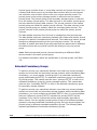
Extended Consistency Groups
To perform remote copy operations between more than one primary storage
system and more than one secondary storage systems while maintaining data
consistency, you must register journal groups in an extended consistency
group (abbreviated as EXCTG). An extended consistency group is a collection
of journal groups. This manual uses the term "primary EXCTG" to refer to an
extended consistency group for primary storage systems. This manual also
uses the term "secondary EXCTG" to refer to an extended consistency group
for secondary storage systems.
To perform remote copy operations between more than one primary storage
system and more than one secondary storage systems while maintaining data
consistency, you must configure a secondary EXCTG. Also, it is recommended
that you configure a primary EXCTG, because the primary EXCTG will be
necessary if you need to reverse the primary and secondary sites after a
failure occurs. You can register journal groups of up to four different storage
systems in the same extended consistency group, but you cannot register one
journal group in different extended consistency groups. The following table
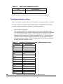
explains specifications of extended consistency groups:
2-14
Chapter 3 Preparing for Universal Replicator z/OS Operations
Hitachi Universal Replicator for IBM /OS User’s Guide
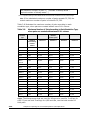
Table 2-2
Specifications of Extended Consistency Groups
Item
The number of extended consistency groups that can be created
The number of journal groups that can be registered in one
extended consistency group
Specifications
Up to four per one storage system
Up to 16
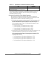
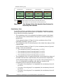
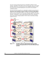
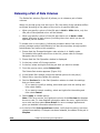
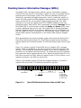
The following explains configuration of extended consistency groups (i.e.,
primary and secondary EXCTGs). Note the following when configuring
extended consistency groups.
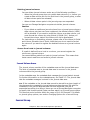
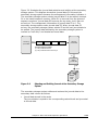
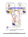
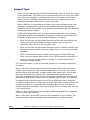
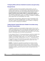
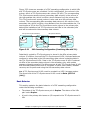
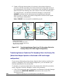
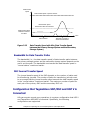
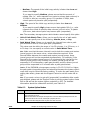
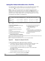
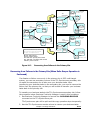
Guaranteed Consistency of Data Update Sequence:
URz restores journal data to secondary data volumes by taking the
following steps. The following procedure guarantees consistency of data
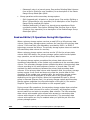
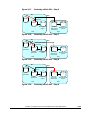
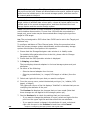
update sequence within an extended consistency group:
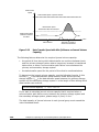
a. URz checks the extended consistency group for the time stamps of all
journal data that have not been restored to secondary data volumes,
and then identifies the latest time stamp for each journal group.
In the example shown in Figure 2-4, the latest time stamp for each
journal group is as follows:
•
In Journal group 1, the latest time stamp is 15:00.
•
In Journal group 2, the latest time stamp is 15:02.
•
In Journal group 3, the latest time stamp is 15:03.
•
In Journal group 4, the latest time stamp is 15:04.
b. URz searches for the oldest time stamp from the ones identified in step
a and restores data up to that time to the secondary volumes.
In the example shown in Figure 2-4, the oldest time stamp is 15:00.
URz restores all data that have a time stamp 15:00 or earlier to the
secondary data volumes.
•
For Journal group 1, URz restores all data up to 15:00.
•
For Journal group 2, URz restores all data up to 14:02.
•
For Journal group 3, URz restores all data up to 14:03.
•
For Journal group 4, URz restores all data up to 14:04.
Chapter 2 About Universal Replicator Operations
Hitachi Universal Replicator for IBM /OS User’s Guide
2-15
Extended consistency group
Journal group 1
Journal group 2
Journal group 3
Journal group 4
15:00
15:02
15:03
15:04
14:00
14:02
14:03
14:04
13:00
13:02
13:03
13:04
12:00
12:02
12:03
12:04
indicates data that is to be restored to secondary data volumes
Legend:
indicates data that is not to be restored to secondary data volumes
Figure 2-4
Time Stamps of Data that Have Not Been Restored to
Secondary Data Volumes
Consistency time:
In the URz windows, consistency times of extended consistency groups,
journal groups, and data volume pairs are displayed. These consistency
times have the following meanings.
–
The consistency time of an extended consistency group is the latest
time stamp of the restored data in the group in which consistency is
guaranteed.
In the example shown in Figure 2-4, the consistency time of the
extended consistency group is 15:00.
–
The consistency time of a journal group is the latest time stamp of the
restored data.
In the example shown in Figure 2-4, the consistency times of journal
groups 1 to 4 are as follows.
–
•
The consistency time of Journal group 1 is 15:00.
•
The consistency time of Journal group 2 is 14:02.
•
The consistency time of Journal group 3 is 14:03.
•
The consistency time of Journal group 4 is 14:04.
The consistency time of a data volume pair is the latest time stamp of
the data that has been restored when the pair becomes suspended.
In the example shown in Figure 2-4, if a pair in the journal group 1, 2,
3 or 4 is suspended immediately after data are restored, the
consistency time of the pair will be as follows.
2-16
•
If a pair in Journal group 1 is suspended, the consistency time will
be 15:00.
•
If a pair in Journal group 2 is suspended, the consistency time will
be 14:02.
•
If a pair in Journal group 3 is suspended, the consistency time will
be 14:03.
Chapter 3 Preparing for Universal Replicator z/OS Operations
Hitachi Universal Replicator for IBM /OS User’s Guide
•
If a pair in Journal group 4 is suspended, the consistency time will
be 14:04.
If a failure occurs in a primary storage system and then you wish to
recover from the failure, please restore journal data with time stamps later
than the consistency time of the extended consistency group to secondary
data volumes. For example, in the case described in Figure 2-4, the
consistency time of the extended consistency group is 15:00, and therefore
you must restore the following data to secondary data volumes.
•
Data with the time stamp 15:02 in journal group 2
•
Data with the time stamp 15:03 in journal group 3
•
Data with the time stamp 15:04 in journal group 4
If a failure occurs in a secondary storage system and then you wish to
recover from the failure, please compare the consistency times of all
journal groups in the extended consistency group, and then identify the
oldest consistency time. Next, please restore all data with time stamps
later than the oldest consistency time, to the secondary data volume. For
example, in the case described in Figure 2-4, the consistency time of
journal group 2 is the oldest among journal groups 1 to 4. Since the
consistency time of journal group 2 is 14:02, you must restore the
following data to secondary data volumes.
•
Data with the time stamp 15:00 in journal group 1
•
Data with the time stamp 15:02 in journal group 2
•
Data with the time stamp 14:03, and data with the time stamp
15:03 in journal group 3
•
Data with the time stamp 14:04, and data with the time stamp
15:04 in journal group 4
Host I/O Time-Stamp
If you plan to establish URz journal groups, the I/O time-stamping function
must be installed on the host processor at the primary site. The I/O timestamp, which is provided by MVS DFSMSdfp, is the same time-stamp that is
used by Compatible XRC pairs. The I/O time-stamping function should also be
installed on the host processor at the secondary site, so that time-stamps can
be used when copying data in the reverse direction.
Note: If the system at the primary and/or secondary site consists of several
CPU complexes, a SYSPLEX timer is required to provide a common time
reference for the I/O time-stamping function.
Chapter 2 About Universal Replicator Operations
Hitachi Universal Replicator for IBM /OS User’s Guide
2-17
Error Reporting Communications (ERC)
Error reporting communications (ERC), which transfers information between
host processors at the primary and secondary sites, is a critical component of
any disaster recovery effort. You can configure ERC using channel-to-channel
communications, NetView technology, or other interconnect technologies,
depending on your installation requirements and standards. Neither URz nor
the URz remote console software provides ERC between the primary and
secondary sites.
When URz is used as a data migration tool, ERC is recommended but is not
required. When URz is used as a disaster recovery tool, ERC is required to
ensure effective disaster recovery operations. When a URz pair is suspended
due to an error condition, the primary storage system generates sense
information which results in an IEA491E system console message. This
information should be transferred to the primary site via the ERC for effective
disaster detection and recovery.
Remote Copy Operations
Figure 2-5 illustrates the two types of URz remote copy operations: initial copy
and update copy.
Secondary host
Primary host
Write instruction
Obtaining updated
journal data
Restore
Update copy
Primary
data
volume
Master
journal
volume
Initial copy
Restore
journal
volume
Secondary
data
volume
Obtaining base-journal
Primary storage system
Figure 2-5
Secondary storage system
Remote copy operations
This section describes the following topics that are related to remote copy
operations with URz:
•
2-18
Initial copy operation (see the next section)
Chapter 3 Preparing for Universal Replicator z/OS Operations
Hitachi Universal Replicator for IBM /OS User’s Guide
•
Update copy operation
•
Read and write I/O operations for URz volumes
•
Secondary data volume write option
•
Secondary data volume read option
•
Difference management
Initial Copy Operations
Initial copy operations synchronize data in the primary data volume and data
in the secondary data volume. Initial copy operations are performed
independently from host I/Os. Initial copy operations are performed when you
create a data volume pair or when you resynchronize a suspended pair. The
initial copy operation copies the base-journal data that is obtained from the
primary data volume at the primary storage system to the secondary storage
system, and then restores the base-journal to the secondary data volume.
If the journal-obtain operation starts at the primary data volume, the primary
storage system obtains all data of the primary data volume as the basejournal data, in sequence. The base-journal contains a replica of the entire
data volume or a replica of updates to the data volume. The base-journal will
be copied from the primary storage system to the secondary storage system
after the secondary storage system issues a read-journal command. After a
base-journal is copied to the secondary storage system, the base-journal will
be stored in a restore journal volume in a restore journal group where the
secondary data volume belongs. After that, the data in the restore journal
volume will be restored to the secondary data volume, so that the data in the
secondary data volume synchronizes with the data in the primary data
volume.
The base-journal data is stored in the entire data volume or the area for the
difference. The area for the difference is used when the difference
resynchronization operation is performed. The journal data for the entire data
volume is created when the data volume pair is created. The difference journal
data is obtained when the pair status of the data volume changes from the
Suspending status to the Pair resync status. Merging the difference bitmaps
that are recorded on both primary and secondary data volumes enables you to
obtain the journal data for only difference. When a data volume pair is
suspended, the status of data that is updated from the host to the primary and
secondary data volumes is recorded to the difference bitmap.
The base-journal data of primary storage system is stored to the secondary
storage system journal volume according to the read command from the
secondary storage system. After that, the base-journal data is restored from
the journal volume to the secondary data volume. The initial copy operation
will finish when all base-journals are restored.
Chapter 2 About Universal Replicator Operations
Hitachi Universal Replicator for IBM /OS User’s Guide
2-19
Note: If you manipulate volumes (not journal groups) to create or
resynchronize two or more data volume pairs within the same journal group,
the base journal of one of the pairs will be stored in the restore journal volume,
and then the base journal of another pair will be stored in the restore journal
volume. Therefore, the operation for restoring the latter base journal will be
delayed.
Note: You can specify None as the copy mode for initial copy operations. If the
None mode is selected, initial copy operations will not be performed. The
None mode must be used at your responsibility only when you are sure that
data in the primary data volume is completely the same as data in the
secondary data volumes.
Update Copy Operation
When a host performs a write I/O operation to a primary data volume of a
data volume pair, an update copy operation will be performed. During an
update copy operation, the update data that is written to the primary data
volume is obtained as an update journal. The update journal will be copied to
the secondary storage system, and then restored to the secondary data
volume.
The primary storage system obtains update data that the host writes to the
primary data volume as update journals. Update journals will be stored in
journal volumes in the journal group that the primary data volume belongs to.
When the secondary storage system issues "read journal" commands, update
journals will be copied from the primary storage system to the secondary
storage system asynchronously with completion of write I/Os by the host.
Update journals that are copied to the secondary storage system will be stored
in journal volumes in the journal group that the secondary data volume
belongs to. The secondary storage system will restore the update journals to
the secondary data volumes in the order write I/Os are made, so that the
secondary data volumes will be updated just like the primary data volumes are
updated.
Journal Group Operations
URz journal groups enable update sequence consistency to be maintained
across a journal group of volumes. The primary data volumes and secondary
data volumes of the pairs in a journal group must be located within one
physical primary storage system and one physical secondary storage system
(1-to-1 requirement).
When more than one data volume is updated, the order that the data volumes
are updated is managed within the journal group that the data volumes belong
to. Consistency in data updates is maintained among paired journal groups.
URz uses journal groups to maintain data consistency among data volumes.
2-20
Chapter 3 Preparing for Universal Replicator z/OS Operations
Hitachi Universal Replicator for IBM /OS User’s Guide
This section describes the following journal group operation options available
in URz:
•
Timer type option
•
Journal group operations
Timer Type Option
The timer type option allows you to specify the method applied by the primary
storage system to acquire the time-stamp information for each journal data.
The following timer types are available for selection:
•
System. When the System timer option is selected, the primary storage
system acquires the time-stamp information for each journal data as
follows. When a URz pair is established, the primary storage system
reports state-change-interrupt (SCI) to all hosts. The host then issues a
series of sense group commands to determine the device status change,
and the primary storage system returns the same response as if the device
had been added to an XRC session to activate I/O time-stamping for the
device. Once I/O time-stamping is activated, the MVS IOS routine attaches
the time-stamp information (contents of time-of-day (TOD) clock) to each
write I/O operation for the device. The time-stamp indicates the time that
the update was generated during start sub-channel (SSCH) at the main
host system, and the time-stamp is transferred to the primary storage
system at the beginning of each I/O operation.
•
Local. When the Local timer option is selected, the primary storage
system does not acquire time-stamp information from the host I/O timestamping function.
•
None. This timer option can be selected only when the copy direction of a
URz volume pair is in reverse direction (i.e., from the secondary site to the
primary site).
When the None option is selected, the primary storage system acquires
time-stamp information from the host I/O time-stamping function.
Journal Group Operations
URz provides the following group-based operations to simplify and expedite
disaster or failure recovery procedures:
•
Group operations at the primary storage system
–
Split all pairs in a journal group. See section Splitting a Mirror
(Suspending a copy operation) for a description of the Suspend RangeGroup suspend pair option.
–
Resume all suspended pairs in a journal group. See section Restoring a
Mirror (Resuming a copy operation) for a description of the URz Resume
Range-Group resume pair option.
Chapter 2 About Universal Replicator Operations
Hitachi Universal Replicator for IBM /OS User’s Guide
2-21
–
•
Release all pairs in a journal group. See section Deleting Data Volumes
from a Mirror (Ending a copy operation) for a description of the Delete
Range-Group delete pair option.
Group operations at the secondary storage system
–
Split (suspend pair) all pairs in a journal group. See section Splitting a
Mirror (Suspending a copy operation) for a description of the Suspend
Range-Group suspend pair option.
–
Release (delete pair) all pairs in a journal group regardless of their
consistency status. See section Deleting Data Volumes from a Mirror
(Ending a copy operation) for a description of the Delete Range-Group
delete pair option.
Read and Write I/O Operations During URz Operations
When a primary storage system receives a read I/O for a URz primary data
volume, the primary storage system performs the read from the primary data
volume. If the read fails, the redundancy provided by RAID-1 or RAID-5
technology recovers the failure. The primary storage system does not read the
URz secondary data volume for recovery.
When a primary storage system receives a write I/O for the primary data
volume with PAIR status, the primary storage system performs the update
copy operation, as well as writing to the primary data volume.
The primary storage system completes the primary data volume write
operations independently of the update copy operations at the secondary data
volume. The secondary storage system updates the data in the secondary data
volume according to the write sequence number of journal data. This will
maintain the data consistency between the primary and secondary data
volumes. If the primary data volume write operation fails, the primary storage
system reports a unit check and does not create the journal data for this
operation. If the update copy operation fails, the secondary storage system
suspends either the affected pair or all URz pairs in the journal group,
depending on the type of failure. When the suspended URz pair or journal
group is resumed (Resume Pair), the primary storage system and secondary
storage system negotiate the resynchronization of the pair(s). See section
Suspend Types for further information on URz suspend types.
During normal URz operations, the secondary storage system does not allow
URz secondary data volumes to be online (mounted), and therefore hosts
cannot read from and write to secondary data volumes. The URz secondary
data volume write enable option allows write access to a secondary data
volume while the pair is split (see the next section). The secondary data
volume write option can only be enabled when you split the pair from the
primary storage system.
2-22
Chapter 3 Preparing for Universal Replicator z/OS Operations
Hitachi Universal Replicator for IBM /OS User’s Guide
Note: When you issue the DEVSERV command to the URz secondary data
volume, INDETERMINATE FAILING UNIT is returned, if the status of URz
secondary data volume is online. INTERVENTION REQUIRED is returned, if
the status of URz secondary data volume is offline.
Secondary Data Volume Write Option
For additional flexibility, URz provides a secondary data volume write option
(S-Vol. Write) which enables write I/O to the secondary data volume of a split
URz pair. The secondary data volume write option can be selected by the user
during the Suspend Pair operation and applies only to the selected pair(s). The
secondary data volume write option can be accessed only when you are
connected to the primary storage system. When you resync a split URz pair
which has the secondary data volume write option enabled, the secondary
storage system sends the secondary data volume track bitmap to the primary
storage system, and the primary storage system merges the primary data
volume and secondary data volume bitmaps to determine which tracks are
out-of sync. This ensures proper resynchronization of the pair.
Secondary Data Volume Read Option
For additional flexibility, URz offers a special secondary data volume read
option. The Hitachi representative enables the secondary data volume read
option on the secondary storage system (mode 20). The secondary data
volume read option allows you to read a URz secondary data volume only
while the pair is suspended, that is, without having to release the pair. The
secondary storage system will allow you to change only the VOLSER of the
suspended secondary data volume, so that the secondary data volume can be
online to the same host as the primary data volume while the pair is
suspended. All other write I/Os will be rejected by the secondary subsystem.
The primary storage system copies the VOLSER of the primary data volume
back onto the secondary data volume when the pair is resumed. When the
secondary data volume read option is not enabled and/or the pair is not
suspended, the secondary storage system rejects all read and write I/Os to a
URz secondary data volume.
Difference Management
The differential data (updated by write I/Os during split or suspension)
between the primary data volume and the secondary data volume is stored in
each track bitmap. When a split/suspended pair is resumed (Resume Pair), the
primary storage system merges the primary data volume and secondary data
volume bitmaps, and the differential data is copied to the secondary data
volume.
Chapter 2 About Universal Replicator Operations
Hitachi Universal Replicator for IBM /OS User’s Guide
2-23
Note: The number of bitmap areas affects the maximum possible number of
pairs that can be created in the storage system. For details on the maximum
possible number of pairs, see section The Maximum Number of Pairs.
Journal Processing
The URz journal data contains the primary data volume updates and the
metadata information (associated control information), which enables the
secondary storage system to maintain update consistency of the URz
secondary data volumes. URz journal processing includes:
•
Creating and storing journals at the primary storage system (see the next
section),
•
Copying journals to the secondary storage system
•
Storing journals at the secondary storage system
•
Selecting and restoring journals at the secondary storage system
•
Types of journals
Journal Processing at the Primary Storage System
When a primary storage system performs an update (host-requested write
I/O) on a URz primary data volume, the primary storage system creates a
journal data to be transferred to secondary storage system. The journal data
will be stored into the cache at first, and then into the journal volume.
Metadata information will be attached to journal data (see Table 2-3). When
base-journal is obtained, only metadata information is created and stored in
UR cache or the journal volume.
Table 2-3
Metadata Information
Type
2-24
Description
Journal type
Type of journal (e.g., base-journal or update journal)
LDEV No. (data)
The number of primary data volume that stores the original data
Original data storing position
The primary data volume slot number, and the start and end of sub-block
number (data length)
LDEV No. (journal)
The volume number of master journal volume that stores the journal data
Journal data storing position
The slot number of master journal volume, and the start sub-block number
Journal sequence number
The sequence number that is assigned when the journal is obtained
Timestamp
The time when the journal data is obtained
Chapter 3 Preparing for Universal Replicator z/OS Operations
Hitachi Universal Replicator for IBM /OS User’s Guide
The journal sequence number indicates the primary data volume write
sequence that the primary storage system has created for each journal group.
The journal data is transferred to the secondary storage system
asynchronously with the host I/O. The secondary storage system updates the
secondary data volume in the same order as the primary data volume
according to the sequence number information in the journal.
Note: URz processing continues uninterrupted if the SVP reboots or even if the
SVP fails.
Types of Journal
In addition to the journal data for updating, the primary storage system sends
control information to the secondary storage system. This control information
indicates when volume pair status changes and when a primary storage
system power-off sequence is initiated, and also maintain sequence numbers
in periods of low host activities.
Journal Processing at the Secondary Storage System
When a primary storage system receives a read journal command from a
secondary storage system, the primary storage system sends the journal data
to the secondary storage system. The secondary storage system’s initiator
ports act as host processor channels and issue special I/O operations, called
remote I/Os (RIOs), to the primary storage system. The RIO transfers the
journal data in FBA format using a single channel command. The primary
storage system can send several journal data using a single RIO, even if their
sequence numbers are not contiguous. Therefore, the journal data are usually
sent to the secondary storage system in a different order than the journal data
were created at the primary storage system. The secondary storage system
ensures that the journal data are applied to the secondary data volume in the
correct sequence. This method of remote I/O provides the most efficient use of
primary storage system-to-secondary storage system link resources.
Note: You must make sure that your channel extenders are capable of
supporting remote I/O. For further details, please contact your Hitachi account
team.
Storing Journal at the Secondary Storage System
A secondary storage system receives the journal data that is transferred from
a primary storage system according to the read journal command. The journal
data will be stored into the cache at first, and then into the journal volume.
Chapter 2 About Universal Replicator Operations
Hitachi Universal Replicator for IBM /OS User’s Guide
2-25
Note: The primary storage system does not remove the target journal data from
its master journal volume until it receives the sequence numbers of restored
journal which is give to the read journal command from the secondary storage
system. This is true even if the primary storage system and secondary storage
system are connected via a channel extender product.
Selecting and Restoring Journal at the Secondary Storage System
The secondary storage system selects journal data to be promoted to formal
data (or " restored") as follows:
1. The secondary storage system gives the number as the management
information to distinguish the journal data arrival to the sequence number
that is assigned to the journal data from the primary storage system. If the
number is 1, the journal data arrived at the secondary storage system. If
the number is 0, the journal data has not arrived yet. The secondary
storage system determines whether the journal data should be settled or
not according to this number. If the journal data has not arrived yet, the
secondary storage system waits for the journal data.
2. When the top of queue in the journal group indicates the journal data
arrival, the secondary storage system selects the journal data which has
the lowest sequence number, and then settles this journal data.
3. The secondary storage system repeats steps (1) and (2) to select and
settle the journal data.
2-26
Chapter 3 Preparing for Universal Replicator z/OS Operations
Hitachi Universal Replicator for IBM /OS User’s Guide
Figure 2-6 illustrates the journal data selection and settling at the secondary
storage system. This diagram shows that journal data S1 arrives at the
secondary storage system because the management information indicates 1.
The secondary storage system selects journal data S1 to be settled, because
S1 is the lowest sequence number. When S1 is removed from the queue of
sequence numbers, journal data S2 becomes the top entry, but it has not
arrived yet. The management information of journal data S2 is 0. The
secondary storage system waits journal data S2. When journal data S2
arrives, the secondary storage system selects S2 as the next journal data to
be settled. The journal data selected by the secondary storage system is
marked as “host-dirty” and treated as formal data.
Receiving
journal data
Grp=n
S4 (1)
S3 (1)
S2 (0)
S1 (1)
Selecting
journal data
S1 to S4: Sequence number
(1): The journal data arrived.
(0): The journal data has not arrived yet.
S1
Setting
journal data
Data
Grp=n
Formal
journal
data
Figure 2-6
Selecting and Settling Journal at the Secondary Storage
System
The secondary storage system settles and restores the journal data to the
secondary data volume as follows:
•
Journal data stored in the cache
The journal data is copied to the corresponding cached track and promoted
to formal data.
Chapter 2 About Universal Replicator Operations
Hitachi Universal Replicator for IBM /OS User’s Guide
2-27
•
Journal data stored in the restore journal volume
The journal data is read from the restore journal volume to cache. The
journal data that is read to cache is copied to the existing cache track and
promoted to formal data. After that, the space for the restore journal
volume is released.
URz Delta Resync Operation
When you are using URz and TCz Synchronous in a 3DC multi-target
configuration, URz provides delta resync operation as one of the solutions for
failures in primary site. In a 3DC multi-target configuration, there are one
primary site and two secondary sites; TCz Synchronous and URz secondary
sites. For detailed information about 3DC multi-target configuration, see
section TCz Synchronous (3DC Multi-target Configuration).
If a failure occurs on the primary site in 3DC multi-target configuration, you
need to use Business Continuity Manager to use the TCz Synchronous
secondary site as the primary site. If you perform a delta resync operation
after the TCz Synchronous secondary site becomes a primary site. The URz
pair will be restored quickly by the delta resync operation, you will not need to
wait for a long time before you can use the URz data volumes again.
Delta resync operation consists of the two processes; one is the process for
the preparation before the failure occurs, the other is the process for the
recovery after the failure occurs.
•
Processing for the preparation before the failure occurs (see the next
section)
•
Processing for the recovery after the failure occurs (see section Switching
the Master Journal Group of URz)
Journal Obtain in TCz Synchronous Secondary Site
To perform delta resync operation when a failure occurs, you also need to
obtain the journal data in the TCz Synchronous secondary site of 3DC multitarget configuration. Specify the TCz Synchronous R-VOL in TCz Synchronous
secondary site as the primary data volume, and specify the data volume in
URz secondary site as the secondary data volume, in order to create a URz
pair for the delta resync operation.
When you create a URz pair for delta resync operation, the differential data of
data volumes in TCz Synchronous primary site and secondary site will be
stored in the journal volumes in TCz Synchronous secondary site as journal
data. The following figure shows an example.
2-28
Chapter 3 Preparing for Universal Replicator z/OS Operations
Hitachi Universal Replicator for IBM /OS User’s Guide
TCz Synchronous, URz primary site
URz secondary site
primary host
secondary host
Write
journal obtain
journal restore
journal
copy
M-VOL
primary data VOL
secondary
dataVOL
master JNL VOL
restore JNL VOL
primary subsystem
Copying by TCz
Synchronous
secondary subsystem
TCz Synchronous
secondary site
secondary
host
journal obtain
R-VOL
primary data VOL
master JNL VOL
secondary subsystem
Data flow
URz pair for delta resync operation
Figure 2-7
Journal data flow
Delta Resync Setting in 3DC Multi-target Configuration
(Before Failure Occurs)
As shown in
Chapter 2 About Universal Replicator Operations
Hitachi Universal Replicator for IBM /OS User’s Guide
2-29
Figure 2-7, a URz pair created with the delta resync option is defined as a pair
but no copy operation is performed (Hold status). Actual copy operation will
not be performed until when the failure occurs and delta resync operation is
performed. Note that there are several requirements to create a URz pair for
delta resync operation, such as you need to specify the unused mirror ID. For
detailed information about the requirements of creating a URz pair for delta
resync operation, see section Requirements for Creating URz Pair for Delta
Resync Operation.
For the information about the delta resync operation that will be performed
when a failure occurs in the configuration shown in
Figure 2-7, see the next section. Note that the URz pair need to be in Hold
status if you want to form the delta resync operation when the failure occurs.
However, the URz pair status may be changed to Hlde for example when the
cache memory or shared memory error occurs in TCz Synchronous secondary
site, or when no journal cannot be obtained in TCz Synchronous secondary site
because of the failure in the master journal volume or occurrence of the
pinned track. If the status of the URz pair for delta resync operation changes
to Hlde, follow the steps in section Restoring a Pair of Data Volumes and
change the pair status to Hold again.
Switching the Master Journal Group of URz
When a failure occurs on the primary site in
Figure 2-7 (3DC multi-target configuration), the URz pair for delta resync
operation can use the journal group in TCz Synchronous secondary site as the
master journal group. To switch the master journal group, first change TCz
Synchronous secondary site to the primary site by using Business Continuity
Manager, then perform the delta resync operation on the primary data volume
of the URz pair in Hold status. The following figure shows an example.
2-30
Chapter 3 Preparing for Universal Replicator z/OS Operations
Hitachi Universal Replicator for IBM /OS User’s Guide
TCz Synchronous, UR primary site A
URz secondary site
primary host
secondary host
journal restore
secondary
dataVOL
M-VOL
primary data VOL
Failure
restore
JNL VOL
master
JNL VOL
primary
subsystem
secondary
subsystem
TCz Synchronous
primary site B
(former secondary site)
journal copy
primary host
(former
secondary host)
Write
journal obtain
primary data VOL
(former R-VOL)
master
JNL VOL
primary subsystem
(former secondary subsystem)
Data flow
URz pair for delta resync operation
Figure 2-8
Journal data flow
Delta Resync Setting in 3DC Multi-target Configuration
(After Failure Occurred)
Chapter 2 About Universal Replicator Operations
Hitachi Universal Replicator for IBM /OS User’s Guide
2-31
In Figure 2-8, because a failure occurs in the primary site A, Business
Continuity Manager is used to change the former TCz Synchronous secondary
site to the primary site B. If you perform delta resync operation in this
situation, the URz pair for delta resync operation in Figure 2-7 will be
synchronized and usable.
When you perform delta resync operation, first the journal data in the primary
site B are copied to the URz secondary site by journal copy. In this journal
copy, only the journal data which is not yet restored to the secondary data
volume in the URz secondary site are copied in chronological order. When the
journal copy completes, journal restore takes place in the URz secondary site.
In delta resync operation, the status of the URz pair will not change to Pending
Duplex but Duplex. This is because delta resync operation copies only the
really necessary data by journal copying. Compared to the usual way which
copies the whole data in the primary data volume, delta resync operation
requires shorter time for the recovery of the URz pair after a failure occurs.
Note: When the total capacity of stored journal data exceeds 80% of the
journal volume of TCz Synchronous secondary site, old journal data will be
deleted automatically. Therefore, if the total capacity of the journal data which
is not restored to the URz secondary data volume exceeds 80% of the journal
volume, the secondary data volume will not be able to be restored completely
by copying the journal data to the restore journal volume in the URz
secondary site. In that case, according to the setting of the journal group
option, whole data in the primary data volume will be copied to the secondary
data volume, or delta resync operation finishes without any processing.
Usually, if the pair between TCz Synchronous primary site and secondary site
is synchronized periodically, the total capacity of the journal data which is not
restored to the URz secondary site will not exceed 80% of the journal volume.
Though, for example if the URz pair is suspended and the pair has not been
resynchronized for a long time, journal data of more than 80% of the journal
volume capacity may be stored before they are restored to URz secondary
data volume. In such case, note that you may not perform delta resync
operation properly.
Warning: Even if the capacity of the journal data does not exceed 80% of the
journal volume, note that journal data will or may be destroyed in the
following cases.
2-32
•
When you restore the TCz Synchronous pair, then updated the M-VOL
•
When you restore the URz pair between the primary site and the URz
secondary site, then updated the M-VOL
•
When the retry processing occurs because of a delay of the M-VOL update
•
When the update of the TCz Synchronous R-VOL is delayed
Chapter 3 Preparing for Universal Replicator z/OS Operations
Hitachi Universal Replicator for IBM /OS User’s Guide
As shown in Figure 2-8, after delta resync operation is performed properly and
the primary site A is recovered from the failure, then the URz pair between the
primary site A and the URz secondary site will be the pair for delta resync
operation and become prepared for the failure in the primary site B. For
information about the requirements to perform delta resync operation properly,
see section Requirements for Performing Delta Resync Operation.
Pair Status
URz displays the pair status for each data volume of specified CU Image (CUI)
in the connected USP V storage system. Table 2-4 lists and describes the URz
data volume pair status descriptions. The primary storage system maintains
the status of the primary data volume and can change the pair status of the
primary data volume and secondary data volume. The secondary storage
system maintains the status of the secondary data volume and can change the
pair status of the secondary data volume but not the primary data volume.
The primary storage system will detect when the secondary storage system
changes the secondary data volume status (if the path status is normal) and
will change the primary data volume status accordingly. You can display the
detailed pair status information at the Storage Navigator remote console PC
(URz Pairdisplay window) or at the host processor (Business Continuity
Manager Pairdisplay command).
A volume which is not assigned to a URz data volume pair has the status
simplex. When a URz data volume pair is started, the primary storage system
changes the status of the primary data volume and secondary data volume to
pending duplex. When the initial copy operation is complete, the primary
storage system changes the status of both data volumes to duplex. When a
pair is suspended from the primary storage system, the primary storage
system changes the status of the primary data volume and secondary data
volume (if the path status is normal) to suspended. When a pair is suspended
from the secondary storage system, the secondary storage system changes
the status of the secondary data volume to suspended, and the primary
storage system detects the pair suspension (if the path status is normal) and
changes the primary data volume status to suspended. When you release a
pair from the primary storage system, the primary storage system changes
the status of the primary data volume and secondary data volume (if the path
status is normal) to simplex. When you release a pair from the secondary
storage system, the secondary storage system changes the secondary data
volume status to simplex, and the primary storage system detects the pair
release (if the path status is normal) and changes the primary data volume
status to suspended.
When a URz data volume pair is split or suspended, the primary storage
system generates a service information message (SIM) to notify the host(s). If
SNMP is installed and operational for USP V, this SIM results in an SNMP trap
which indicates the reason for suspension.
Chapter 2 About Universal Replicator Operations
Hitachi Universal Replicator for IBM /OS User’s Guide
2-33
•
URz Pair Status
The URz Suspending and Deleting (release) transitional states occur when
a request to change URz pair status has been accepted, but the change to
the requested status (suspended, or simplex) is not yet complete. These
states are not reported to the host. In the case of Suspending, both the
user and the primary storage system can request the status change. In the
case of Deleting (release), only the user can request the status change. If
the user requested the status change, the final status is reported at the
end of the transition. If an error caused the status to change to suspended,
the suspended status is reported at the beginning of the transition.
After a storage system receives a request for splitting or releasing a pair in
Flush mode, the status of the pair will remain Suspending or Deleting
until the journal in the master journal group is restored into the restore
journal group and the pair is completely split or released. To calculate the
time during which the pair remains Suspending or Deleting, use the
following equation:
C × (u ÷ 100) × 1,024 ÷ V (The unit is seconds)
where:
–
C is the total capacity of the master journal volume. The unit is
megabytes.
–
u is the usage rate of data in the master journal volume. The unit is
percent.
–
V is the data transfer speed between the primary and the secondary
storage system. The unit is MB/s (megabytes per second).
To find the usage rate of a journal volume, use the monitoring feature (see
Usage Monitor Window).
The URz SEQCHK status is indicated when a URz pair assigned to a
consistency group with the System timer type accepts a non-timestamped update from the primary system. The SEQCHK status does not
affect URz copy activities and will be removed when the next time-stamped
update is successfully copied to the secondary data volume. However, if a
disaster or system failure occurs before the next time-stamped update, the
update sequence consistency between the secondary data volume and
other secondary data volumes in the consistency group is not ensured. To
ensure effective disaster recovery, you should detect and remove the
source of the SEQCHK status. The SEQCHK status can be caused by any of
the following:
2-34
–
An application may issue update I/Os bypassing the MVS standard I/O
procedure.
–
The I/O time-stamping function may not be active at the primary site.
–
This URz pair status describes:
•
URz suspend types (see the next section),
•
URz suspension condition (see section Suspension Condition).
Chapter 3 Preparing for Universal Replicator z/OS Operations
Hitachi Universal Replicator for IBM /OS User’s Guide
Table 2-4
URz Data Volume Pair Status
Pair Status
Description
Simplex
This volume is not currently assigned to a URz data volume pair. This volume
does not belong in the journal group. When this volume is added to a URz data
volume pair, its status will change to pending duplex.
Pending Duplex
The initial copy operation for this pair is in progress. This data volume pair is not
yet synchronized. When the initial copy is complete, the status changes to
duplex.
Duplex
This data volume pair is synchronized. Updates to the primary data volume are
duplicated on the secondary data volume.
Suspended
(see Table 2-5 for
suspend types)
This data volume pair is not synchronized.
– When the primary storage system detects a URz suspension condition (see
section Suspension Condition), the primary storage system changes the primary
data volume status and secondary data volume status (if possible) to
suspended.
– When the secondary storage system detects a URz suspension condition (see
section Suspension Condition), the secondary storage system changes the
secondary data volume status to suspended.
– When you suspend a pair from the primary storage system, the primary storage
system changes the status of the primary data volume and secondary data
volume (if possible) to suspended. When you suspend a pair from the
secondary storage system, the secondary storage system changes the status of
the secondary data volume to suspended.
– When the primary storage system detects that the pair was suspended or
released from the secondary storage system, the primary storage system
changes the status of the primary data volume to suspended.
Suspending
This pair is not synchronized. This pair is in transition from duplex or pending
duplex to suspended. When the suspension is requested (by user, primary
storage system, or secondary storage system), the status of all affected pairs
changes to suspending. When the suspension is complete, the status changes to
suspended.
Deleting
(releasing)
This pair is not synchronized. This pair is in transition from duplex, pending
duplex, or suspended to simplex. When the delete pair operation is requested
(by user), the status of all affected pairs changes to deleting (releasing). When
the delete pair operation is complete, the status changes to simplex.
SEQCHK
The secondary storage system encountered a non-time-stamped journal data
for a URz pair using the System timer type option. This status can be displayed
at the primary storage system and secondary storage system, but the primary
storage system may not have the most current information. Always use the pair
status information displayed at the secondary storage system for disaster
recovery.
Hold
The pair is prepared for delta resync operation. When the status of primary data
volume is Hold, the write data for the TCz Synchronous R-VOL is stored in the
master journal volume.
Only the delta resync operation, releasing operation, or changing pair option
operation are allowed on the pairs in Hold status.
Hlde
An error occurred on the pair in Hold status. When the status of primary data
volume is Hlde, the write data for the TCz Synchronous S-VOL will not be stored
in the master journal volume.
Only recovering pair status to standby (Hold) operation, releasing operation, or
changing pair option operation are allowed on the pairs in Hlde status.
Chapter 2 About Universal Replicator Operations
Hitachi Universal Replicator for IBM /OS User’s Guide
2-35
Suspend Types
Table 2-5 lists and describes the URz suspend types, which indicate the reason
for the suspension. A URz pair can be suspended by the user at any time after
the initial copy operation is complete. The user must suspend a URz pair in
order to perform ICKDSF maintenance on the primary data volume or to
access the secondary data volume (read only mode).
When a URz pair is suspended by the user, the primary storage system and
secondary storage system ensure synchronization by either completing or
discarding any pending update copy operations according to the user-specified
drain/purge suspend option.
A URz pair is suspended by the primary storage system when the following
suspension conditions are detected. A URz pair can also be suspended by the
secondary storage system (see section Suspension Condition).
•
When the primary storage system detects that the user has released the
volume pair from the secondary storage system (e.g., to access an
secondary data volume at the secondary site),
•
When the primary storage system detects an error condition related to the
secondary storage system, secondary data volume, or a URz journal data
operation,
•
When the secondary storage system cannot execute DFW (DASD fast
write) to the secondary data volume (only if DFW required is selected), or
•
When the primary storage system is unable to communicate with the
secondary storage system.
For more information on URz journal data operations, see section Suspension
Condition.
When a URz pair is suspended, the primary storage system stops performing
update copy operations to the secondary data volume. Moreover, the primary
storage system and secondary storage system keep track of any journal data
that were discarded during suspension, and the primary storage system
continues accepting write I/Os for the primary data volume and keeps track of
the primary data volume tracks which are updated while the pair is suspended.
A suspended URz secondary data volume has an additional status called the
consistency status which is displayed only at the secondary storage system. The
consistency status of a suspended URz secondary data volume indicates its
update sequential consistency with respect to the other secondary data volumes
in the same group.
Table 2-7 lists and describes the consistency status descriptions for suspended
URz secondary data volumes.
When a URz pair is suspended, whether user-requested or due to failure, the
primary storage system generates sense information to notify the host(s).
2-36
Chapter 3 Preparing for Universal Replicator z/OS Operations
Hitachi Universal Replicator for IBM /OS User’s Guide
Table 2-5
Suspend Types
Suspend Type
Applies to
Description
Secondary
data volume
by operator
Primary data
volume, secondary
data volume
The user suspended the pair from the primary storage system or
secondary storage system using the secondary data volume option.
By MCU
Secondary data
volume
The secondary storage system received a request from the primary storage
system to suspend the volume pair. The primary data volume suspend
type is Primary data volume by Operator or Secondary data volume by
Operator.
By RCU
Primary data
volume
The primary storage system detected an error condition at the secondary
storage system which caused the primary storage system to suspend the
URz volume pair. The secondary data volume suspend type is By MCU.
Delete Pair to
RCU
Primary data
volume
The primary storage system detected that the secondary data volume
status changed to simplex because the user released the pair from the
secondary storage system. The pair cannot be resumed because the
secondary data volume does not have the suspended status.
Secondary
Data Volume
Failure
Primary data
volume
The primary storage system detected an error during communication with
the secondary storage system or an I/O error during update copy. In this
case, the secondary data volume suspend type is usually By MCU.
MCU IMPL
Primary data
volume, secondary
data volume
The primary storage system could not find valid control information in its
nonvolatile memory during the IMPL procedure. This condition occurs only
if the primary storage system is completely without power for more than
48 hours (e.g., power failure and fully discharged backup batteries).
Initial Copy
failed
Primary data
volume, secondary
data volume
The volume pair was suspended before the initial copy operation was
complete. The data on the secondary data volume is not identical to the
data on the primary data volume.
JNL Cache
Overflow
Primary data
volume, secondary
data volume
The data volume pair was suspended because it was highly likely that
journal data will overflow.
MCU P/S OFF
Secondary data
volume
The primary storage system is powered off.
Table 2-6
Consistency Status for Suspended URz Secondary Data
Volumes
Consistency Status
Volume
Description
This URz volume pair was suspended alone. Update sequence consistency between this
secondary data volume and other secondary data volumes in this journal group is not
ensured. This secondary data volume cannot be used for disaster recovery at the secondary
system. This status is indicated when:
–
This volume pair was suspended by a user-initiated suspend pair operation with the
URz Suspend option set to Volume.
–
This volume pair was suspended due to a failure that did not affect the entire
consistency group, and the Error Level pair option for this pair is set to Volume.
Chapter 2 About Universal Replicator Operations
Hitachi Universal Replicator for IBM /OS User’s Guide
2-37
Group
This URz volume pair was suspended along with the other pair in its journal group. Update
sequence consistency between this secondary data volume and other secondary data
volumes in this journal group is ensured. This secondary data volume can be used for disaster
recovery at the secondary system (after releasing the URz volume pair from the secondary
storage system). This status is indicated when:
–
This volume pair was suspended by a user-initiated suspend pair operation with the
URz Suspend option set to Group.
–
All volume pairs in this journal group were suspended due to a failure that affected
the entire journal group (not just one pair) (e.g., primary storage system-secondary
storage system communication failure).
–
The volume pair was suspended due to a failure that did not affect the entire group.
Suspension Condition
URz operations also involve suspension conditions related to asynchronous
operations. Both the primary storage system and secondary storage system
can detect URz suspension conditions and suspend URz pairs.
The URz suspension conditions described in Table 2-7 and indicates which CU
detects the condition and which pairs are suspended. See section General
Troubleshooting for troubleshooting information for URz suspension conditions.
Table 2-7
URz Suspension Condition
Suspension Condition
Detected by:
URz Pairs to be Suspended
The secondary storage system could not copy the
journal data successfully due to a hardware failure or
logic error.
RCU
All URz secondary data volumes in the
journal groups, or the affected
secondary data volume.
The secondary storage system detected a logical error
while selecting the journal data to be restored.
RCU
The secondary storage system could not restore the
journal data due to a hardware failure, track condition,
or logical error.
RCU
All the URz secondary data volumes in
the journal group, or only the affected
secondary data volume, depending on
the type of failure.
The primary storage system stores the differential bitmap per URz primary
data volume in the shared memory. The secondary storage system stores the
differential bitmap per URz secondary data volume in the shared memory.
When a URz pair is suspended, the tracks which contain the following journal
are marked in the differential bitmap as modified (to be copied during the
resume pair operation):
•
The journal data that were created by the primary storage system but not
yet sent to the secondary storage system.
After marking these primary data volume tracks as modified, the primary
storage system discards these journal data.
•
2-38
The journal data that were sent to the secondary storage system but not
acknowledged by the secondary storage system.
Chapter 3 Preparing for Universal Replicator z/OS Operations
Hitachi Universal Replicator for IBM /OS User’s Guide
After marking these primary data volume tracks as modified, the primary
storage system discards these journal data. This ensures that journal data
lost during transmission to the secondary storage system are identified and
marked.
•
The journal data that reached the secondary storage system but have not
yet been settled.
After marking these secondary data volume tracks as modified, the
secondary storage system discards these journal data.
•
The primary data volume records updated by host-requested write I/Os
after the pair was suspended.
When a suspended URz pair is resumed (resynchronized), the contents of the
secondary storage system’s cylinder/track bitmap are sent to the primary
storage system and merged into the primary storage system’s bitmap. The
primary storage system then performs the resync operation according to the
merged bitmap. This ensures that all the tracks including the discarded journal
data are resynchronized at this time.
Business Continuity Manager Support
The USP V storage systems on which URz is installed support the Business
Continuity Manager commands. If the host system console issues the Business
Continuity Manager commands to the USP V storage system, the URz pair
operations can be performed. The Business Continuity Manager commands
allow you to add pairs, suspend pairs, resume pairs, release pairs, monitor the
pair status, add DKC, and delete DKC. Table 2-8 and Table 2-9 explain the
USP V system adapter ID(SAID) values. For further information and
instructions on Business Continuity Manager, please refer to the Business
Continuity Manager User's Guide.
Chapter 2 About Universal Replicator Operations
Hitachi Universal Replicator for IBM /OS User’s Guide
2-39
Table 2-8
Package
Location
Port
SAID
1E
CL1-A
X'000
0'
(Basic)
CL3-A
X'002
0'
CL5-A
SAID Values for the PATH LINK Parameter (FRONT CL1)
Port
SAID
1B
CL9-E
X'0084'
(Add6)
CLB-E
X'00A4'
X'00CC'
CLD-E
X'00C4'
CLF-N
X'00EC'
CLF-E
X'00E4'
X'0009'
CL9-P
X'008D'
CL9-F
X'0085'
CL3-K
X'0029'
CLB-P
X'00AD'
CLB-F
X'00A5'
X'004
1'
CL5-K
X'0049'
CLD-P
X'00CD'
CLD-F
X'00C5'
CL7-B
X'006
1'
CL7-K
X'0069'
CLF-P
X'00ED'
CLF-F
X'00E5'
CL1-C
X'000
2'
CL1-L
X'000A'
CL9-Q
X'008E'
CL9-G
X'0086'
CL3-C
X'002
2'
CL3-L
X'002A'
CLB-Q
X'00AE'
CLB-G
X'00A6'
CL5-C
X'004
2'
CL5-L
X'004A'
CLD-Q
X'00CE'
CLD-G
X'00C6'
CL7-C
X'006
2'
CL7-L
X'006A'
CLF-Q
X'00EE'
CLF-G
X'00E6'
CL1-D
X'000
3'
CL1-M
X'000B'
CL9-R
X'008F'
CL9-H
X'0087'
CL3-D
X'002
3'
CL3-M
X'002B'
CLB-R
X'00AF'
CLB-H
X'00A7'
CL5-D
X'004
3'
CL5-M
X'004B'
CLD-R
X'00CF'
CLD-H
X'00C7'
CL7-D
X'006
3'
CL7-M
X'006B'
CLF-R
X'00EF'
CLF-H
X'00E7'
1F
CL1-E
X'000
4'
1H
CL1-N
X'000C'
1L
CL9-J
X'0088'
1A
CL9-A
X'0080'
(Add1)
CL3-E
X'002
4'
(Add3)
CL3-N
X'002C'
(Add5)
CLB-J
X'00A8'
(Add7)
CLB-A
X'00A0'
CL5-E
X'004
4'
CL5-N
X'004C'
CLD-J
X'00C8'
CLD-A
X'00C0'
CL7-E
X'006
4'
CL7-N
X'006C'
CLF-J
X'00E8'
CLF-A
X'00E0'
CL1-F
X'000
5'
CL1-P
X'000D'
CL9-K
X'0089'
CL9-B
X'0081'
CL3-F
X'002
5'
CL3-P
X'002D'
CLB-K
X'00A9'
CLB-B
X'00A1'
2-40
Package
Location
Port
SAID
1G
CL1-J
X'0008'
(Add2)
CL3-J
X'0028'
X'004
0'
CL5-J
CL7-A
X'006
0'
CL1-B
Package
Location
Port
SAID
1K
CL9-N
X'008C'
(Add4)
CLB-N
X'00AC'
X'0048'
CLD-N
CL7-J
X'0068'
X'000
1'
CL1-K
CL3-B
X'002
1'
CL5-B
Package
Location
Chapter 3 Preparing for Universal Replicator z/OS Operations
Hitachi Universal Replicator for IBM /OS User’s Guide
CL5-F
X'004
5'
CL5-P
X'004D'
CLD-K
X'00C9'
CLD-B
X'00C1'
CL7-F
X'006
5'
CL7-P
X'006D'
CLF-K
X'00E9'
CLF-B
X'00E1'
CL1-G
X'000
6'
CL1-Q
X'000E'
CL9-L
X'008A'
CL9-C
X'0082'
CL3-G
X'002
6'
CL3-Q
X'002E'
CLB-L
X'00AA'
CLB-C
X'00A2'
CL5-G
X'004
6'
CL5-Q
X'004E'
CLD-L
X'00CA'
CLD-C
X'00C2'
CL7-G
X'006
6'
CL7-Q
X'006E'
CLF-L
X'00EA'
CLF-C
X'00E2'
CL1-H
X'000
7'
CL1-R
X'000F'
CL9-M
X'008B'
CL9-D
X'0083'
CL3-H
X'002
7'
CL3-R
X'002F'
CLB-M
X'00AB'
CLB-D
X'00A3'
CL5-H
X'004
7'
CL5-R
X'004F'
CLD-M
X'00CB'
CLD-D
X'00C3'
CL7-H
X'006
7'
CL7-R
X'006F'
CLF-M
X'00EB'
CLF-D
X'00E3'
Table 2-9
Package
Location
SAID Values for the PATH LINK Parameter (REAR CL2)
Port
SAID
Package
Location
Port
SAID
Package
Location
Port
SAID
2Q
CL2-A
X'0010'
2T
CL2-J
X'0018'
2W
CLA-N
X'009C'
(Basic)
CL4-A
X'0030'
(Add2)
CL4-J
X'0038'
(Add4)
CLC-N
X'00BC'
CL6-A
X'0050'
CL6-J
X'0058'
CLE-N
CL8-A
X'0070'
CL8-J
X'0078'
CL2-B
X'0011'
CL2-K
CL4-B
X'0031'
CL6-B
Port
SAID
2N
CLA-E
X'0094
'
(Add6)
CLC-E
X'00B4
'
X'00DC'
CLE-E
X'00D4
'
CLG-N
X'00FC'
CLG-E
X'00F4'
X'0019'
CLA-P
X'009D'
CLA-F
X'0095
'
CL4-K
X'0039'
CLC-P
X'00BD'
CLC-F
X'00B5
'
X'0051'
CL6-K
X'0059'
CLE-P
X'00DD'
CLE-F
X'00D5
'
CL8-B
X'0071'
CL8-K
X'0079'
CLG-P
X'00FD'
CLG-F
X'00F5'
CL2-C
X'0012'
CL2-L
X'001A'
CLA-Q
X'009E'
CLA-G
X'0096
'
CL4-C
X'0032'
CL4-L
X'003A'
CLC-Q
X'00BE'
CLC-G
X'00B6
'
CL6-C
X'0052'
CL6-L
X'005A'
CLE-Q
X'00DE'
CLE-G
X'00D6
'
CL8-C
X'0072'
CL8-L
X'007A'
CLG-Q
X'00FE'
CLG-G
X'00F6'
CL2-D
X'0013'
CL2-M
X'001B'
CLA-R
X'009F'
CLA-H
X'0097
'
Chapter 2 About Universal Replicator Operations
Hitachi Universal Replicator for IBM /OS User’s Guide
Package
Location
2-41
CL4-D
X'0033'
CL4-M
X'003B'
CLC-R
X'00BF'
CLC-H
X'00B7
'
CL6-D
X'0053'
CL6-M
X'005B'
CLE-R
X'00DF'
CLE-H
X'00D7
'
CL8-D
X'0073'
CL8-M
X'007B'
CLG-R
X'00FF'
CLG-H
X'00F7'
2R
CL2-E
X'0014'
2U
CL2-N
X'001C'
2X
CLA-J
X'0098'
2M
CLA-A
X'0090
'
(Add1)
CL4-E
X'0034'
(Add3)
CL4-N
X'003C'
(Add5)
CLC-J
X'00B8'
(Add7)
CLC-A
X'00B0
'
CL6-E
X'0054'
CL6-N
X'005C'
CLE-J
X'00D8'
CLE-A
X'00D0
'
CL8-E
X'0074'
CL8-N
X'007C'
CLG-J
X'00F8'
CLG-A
X'00F0'
CL2-F
X'0015'
CL2-P
X'001D'
CLA-K
X'0099'
CLA-B
X'0091
'
CL4-F
X'0035'
CL4-P
X'003D'
CLC-K
X'00B9'
CLC-B
X'00B1
'
CL6-F
X'0055'
CL6-P
X'005D'
CLE-K
X'00D9'
CLE-B
X'00D1
'
CL8-F
X'0075'
CL8-P
X'007D'
CLG-K
X'00F9'
CLG-B
X'00F1'
CL2-G
X'0016'
CL2-Q
X'001E'
CLA-L
X'009A'
CLA-C
X'0092
'
CL4-G
X'0036'
CL4-Q
X'003E'
CLC-L
X'00BA'
CLC-C
X'00B2
'
CL6-G
X'0056'
CL6-Q
X'005E'
CLE-L
X'00DA'
CLE-C
X'00D2
'
CL8-G
X'0076'
CL8-Q
X'007E'
CLG-L
X'00FA'
CLG-C
X'00F2'
CL2-H
X'0017'
CL2-R
X'001F'
CLA-M
X'009B'
CLA-D
X'0093
'
CL4-H
X'0037'
CL4-R
X'003F'
CLC-M
X'00BB'
CLC-D
X'00B3
'
CL6-H
X'0057'
CL6-R
X'005F'
CLE-M
X'00DB'
CLE-D
X'00D3
'
CL8-H
X'0077'
CL8-R
X'007F'
CLG-M
X'00FB'
CLG-D
X'00F3'
Command Device
To use Business Continuity Manager, you must set the command device for it
separately from the command device for an open system. The command
device for Business Continuity Manager can be set only from Business
Continuity Manager. For information about Business Continuity Manager,
please refer to the Business Continuity Manager User Guide and Reference.
2-42
Chapter 3 Preparing for Universal Replicator z/OS Operations
Hitachi Universal Replicator for IBM /OS User’s Guide
You can use Storage Navigator to find the command device for Business
Continuity Manager. To find the command device, click File, and Basic
Information on the menu bar of the Storage Navigator main window, and
then select the LDEV tab in the Basic Information Display window. For
detailed information on the Basic Information Display window, please refer
to the Storage Navigator User's Guide.
Chapter 2 About Universal Replicator Operations
Hitachi Universal Replicator for IBM /OS User’s Guide
2-43
2-44
Chapter 3 Preparing for Universal Replicator z/OS Operations
Hitachi Universal Replicator for IBM /OS User’s Guide
3
Preparing for Universal Replicator z/OS
Operations
This chapter describes URz operations involving the USP V primary and
secondary storage systems, the remote copy connections between the primary
\secondary storage systems, and the host(s) at the primary and secondary
sites, as well as the licensed URz remote console software:
Requirements and Restrictions for URz
Installing the Hardware
Enabling the URz Option(s)
Using Multiple Primary and Secondary Storage Systems
Interoperability with Other Products and Functions
Planning of Journal Volumes
Contributing Factors for Data Transfer Speed between Storage Systems
Configuration that TagmaStore USP/NSC and USP V is Connected
Chapter 3 Preparing for Universal Replicator z/OS Operations
Hitachi Universal Replicator for z/OS User’s Guide
3-1
Requirements and Restrictions for URz
URz has the following requirements and restrictions:
•
System requirements (see the next section)
•
Disk track format
•
One-to-one volume copy operations
•
Duplicate VOLSER
•
Volume type
•
Journal group
•
Accessing URz primary data volumes and secondary data volumes
•
Cache and NVS
•
Duplicate volume
System Requirements
URz operations involve the USP V primary storage systems and secondary
storage systems containing the primary and secondary data volumes, the
remote copy connections between the primary storage systems and secondary
storage systems, the host(s) at the primary and secondary sites, and the
licensed URz remote console software. The URz system requirements are:
•
primary storage system: USP V storage system with URz installed.
•
secondary storage system: USP V storage system with URz installed.
Note: URz can coexist with UR in the same USP V storage system.
Note: The remote copy connection with the NAS interface is not supported.
3-2
•
Remote copy connections – fibre channel (see section Setting up Remote
Copy Connections):
•
Multimode or single-mode optical fibre cables are required at both the
primary storage system and secondary storage system.
•
For distance up to 0.5 km, multimode optical shortwave fiber cables are
required between the primary storage system and secondary storage
system.
•
For distances from 0.5 km to 1.5 km (1,640 to 4,920 feet), multimode
shortwave fibre-channel interface cables with up to two switches are
required.
•
For distance up to 10 km, single optical long wave fiber cables are required
between the primary storage system and secondary storage system.
•
For distances from 10 km to 30 km (6.2 to 18.6 miles), single-mode long
wave fibre-channel interface cables with up to two switches are required.
Chapter 3 Preparing for Universal Replicator z/OS Operations
Hitachi Universal Replicator for IBM /OS User’s Guide
•
For distances greater than 30 km (18.6 miles), approved third-party
channel extender products and telecommunications lines are required.
Long-distance URz solutions are provided based on user requirements and
workload characteristics.
•
Supported mainframe host operating systems (OS):
USP V supports the following mainframe host operating systems (OS).
–
MVS, OS/390, z/OS, VOS3, MSP-EX
–
Optional error report communications (ERC) function requires MVS/DFP
3.2.0 or later.
–
If the primary and/or secondary systems consist of several CPU
complexes, a SYSPLEX timer is required to provide a common time
reference for the host I/O time-stamping function.
Please contact your Hitachi account team for the latest information on
platform support for URz.
•
A computer that runs Storage Navigator (Storage Navigator computer):
The USP V Storage Navigator remote console software is required for
USP V URz operations. The URz remote console software is a component of
the USP V Storage Navigator software. The URz license key(s) are required
to enable the URz option(s) on the USP V storage system (see section
Enabling the URz Option(s)). Separate license keys are required for each
USP V storage system. For further information on USP V Storage Navigator
operations, please refer to the Storage Navigator User's Guide, or contact
your Hitachi account team.
Note: Administrator or URz write access to the USP V Storage Navigator Java
applet program is required to perform URz operations. Users without
Administrator or URz write access can only view URz information.
•
About the license of Universal Replicator for z/OS®:
If you want to use Universal Replicator for z/OS®, you must install not only
a license for Universal Replicator for z/OS® but also a license for TrueCopy
for z/OS®.
•
Connection with TagmaStore USP/NSC
URz can execute remote copy operations by connecting USP V with
TagmaStore USP/NSC. Specifically, the following configurations are
supported.
–
System configuration for remote copy operation using URz from USP V
to TagmaStore USP/NSC.
–
System configuration for remote copy operation using URz from
TagmaStore USP/NSC to USP V using.
Note: For detailed information about the connection with TagmaStore
USP/NSC, see section Configuration that TagmaStore USP/NSC and USP V
is Connected.
Chapter 3 Preparing for Universal Replicator z/OS Operations
Hitachi Universal Replicator for IBM /OS User’s Guide
3-3
Disk Track Format
URz supports the following requirements on the disk track format, which must
be ensured by the user. URz cannot detect exceptions to these requirements.
The primary storage system will abort the URz initial copy operation if the
track format for both the primary data volume and secondary data volume
does not meet the following requirements.
•
The TCz primary data volume and secondary data volume must have the
same track format.
•
Record zero (R0) must be standard format, with key length of zero and
data length of eight. The primary storage system will abort the initial copy
operation if R0 is not standard format.
•
The CCHH (logical cylinder address and logical head address) of R0 must
be identical to the physical cylinder address and physical head address of
the track.
•
The CCHH of each user record in a track must be unique.
One-to-One Volume Copy Operations
URz requires a one-to-one relationship between the volumes of the volume
pairs. A volume (LDEV) can only be assigned to one URz pair at a time.
However, when creating a URz pair for delta resync operation, you can specify
the secondary data volume of a URz pair that is not for delta resync operation
as the secondary data volume of the URz pair for delta resync operation. In
that case, you need to create a mirror the delta-resync pair and the non-deltaresync pair. For detailed information about delta resync operation, see section
URz Delta Resync Operation and TCz Synchronous (3DC Multi-target
Configuration).
Note: URz does not support operations in which one primary data volume is
copied to more than one secondary data volume, or more than one primary
data volume is copied to one secondary data volume.
Because URz operates on volumes rather than on files, multivolume files
require special attention. For complete duplication and recovery of a
multivolume file (e.g., a large database file which spans several volumes),
make sure that all volumes of the file are copied to URz secondary data
volume, and use URz to ensure update sequence consistency across this group
of secondary data volume.
3-4
Chapter 3 Preparing for Universal Replicator z/OS Operations
Hitachi Universal Replicator for IBM /OS User’s Guide
Duplicate VOLSER (Volume Serial Number)
When you select Entire as the initial copy option, the URz initial copy
operation copies the VOLSER of the primary data volume to the secondary
data volume, and therefore the primary data volume and secondary data
volume of the URz pair will have the same VOLSER. Since the host operating
system does not allow duplicate VOLSERs, the host system administrator must
take precautions to prevent system problems related to duplicate VOLSERs.
For example, the URz secondary data volumes must be defined in the system
generation so they do not come online automatically (see WARNING below).
WARNING: If the volumes which will become URz secondary data volumes are
physically attached to the same system images as the production volumes
which will become the URz primary data volumes, the following problems can
occur:
When a URz pair is released, the old secondary data volume is usually offline.
When a host system is IPL’d (initial program loaded), the operator will be
offered both volumes and asked which volume should be left offline – the old
duplicate volser message. This can be confusing and is prone to error. To
avoid duplication of VOLSER,
1. Identify the volumes that will not be accessed by the host system.
2. Perform CHP OFF or some other operation to ensure that the volumes are
inaccessible.
3. When performing IPL, you must perform LOAD CLEAR.
Volume Types
The following DKC and DKU emulation types can be used for the URz software.
Table 3-1
Supported Emulation Types
Emulation
Support type
DKC
All CU images that can be used with USP V
DKU (Drive)
All mainframe volumes that can be used with USP V
All DKC and DKU (drive) emulation types for USP V can be used for URz
software. In URz, the emulation types of primary and secondary data volumes
are indicated.
The following CU emulation types can be used for MCUs (primary storage
systems) and RCUs (secondary storage systems): 3990-3, 3990-6, 3990-6E,
2105, 2107, A-65A2, H-65A2, A-65C1, A-65C2.
The CU emulation type of an MCU can be different from the CU emulation type
of the corresponding RCU.
Chapter 3 Preparing for Universal Replicator z/OS Operations
Hitachi Universal Replicator for IBM /OS User’s Guide
3-5
Notes:
•
The CU emulation type 3990-6, 3990-6E, 2105, or 2107 is required for
SMS I/O time stamping of URz journals. If one of these CU emulation types
is used, volumes of the 3380 emulation type must not be used.
•
The CU emulation type H-65A2 is used for the HITAC M series and supports
all types of M series volumes.
Table 3-2 lists the volumes and the volume capacity that can be used for the
URz data volume and journal volume.
Note: The capacity of journal volume is not included in the accounting capacity.
Table 3-2
Supported Data Volume and Journal Volume
Type
Support specifications
VLL volume
Available
The volume on which Cache Residency
Manager setting are made
Available
Maximum volume capacity
3380-3
2.377 GB
3380-E
1.26 GB
3380-J
0.63 GB
3380-K
1.890 GB
3390-1
0.964 GB
3390-2
1.892 GB
3390-3
2.838 GB
Data Volume
Journal Volume
Capacity of OPEN-V volumes can
be determined freely, depending
on VLL volume specifications. The
minimum capacity is 48.1 MB,
and the maximum capacity is the
same as the user capacity of one
RAID group.
3390-3R
3390-9
8.510 GB
3390-L
27.80 GB
3390-M
55.60 GB
OPEN-V
OPEN-V volumes cannot be used
as data volumes.
Note: The default capacity of an
OPEN-V volume is the same as the
capacity of a RAID group, and
depends on the hard disk drive type
and the RAID configuration.
3-6
Chapter 3 Preparing for Universal Replicator z/OS Operations
Hitachi Universal Replicator for IBM /OS User’s Guide
Minimum volume capacity
50 cylinders for a non-OPEN-V
volume.
1 cylinder
48.1 MB for an OPEN-V volume.
Note: A journal volume consists of
two types of areas, one for
containing journal data, and the
other for containing information for
managing remote copy operations.
Caution: Volumes containing a VMA (volume management area) cannot be used
as journal volumes. For detailed information about a VMA, please refer to the
Data Retention Utility User's Guide.
The table below explains emulation types and the capacity of volumes that can
form pairs. For details on the maximum number of pairs, see the next section.
Table 3-3
Specifications of Volumes that can Form Pairs
Item
Support specifications
Emulation type
Same emulation type.
Volume capacity
The same capacity.
URz can copy data between volumes with the same emulation and capacity
(e.g., 3390-3R to 3390-3R). URz also supports the Virtual LVI/LUN feature of
the USP V storage system, enabling you to establish URz pairs with customsize emulation types as well as standard-size emulation types. When customsize emulation types are assigned to URz pairs, the secondary data volume
must have the same capacity as the primary data volume. The URz remote
console software displays the emulation type of the primary data volumes and
secondary data volumes.
URz supports the Virtual LVI/LUN feature of the USP V storage system, which
allows you to configure custom-size LDEVs which are smaller than standardsize LDEVs. When custom-size LDEVs are assigned to a URz pair, the
secondary data volume must have the same capacity as the primary data
volume.
Table 3-4 shows the emulation types and capacity of master and restore
journal volumes that can be used for a URz software.
Table 3-4
Journal Volume Specifications
Item
Support specifications
Emulation type
Same emulation type.
Volume capacity
Does not matter whether the capacity is the
same or different.
Table 3-5 shows the RAID level combination of data volume and journal
volume in the journal group that can be used for URz.
Chapter 3 Preparing for Universal Replicator z/OS Operations
Hitachi Universal Replicator for IBM /OS User’s Guide
3-7
Table 3-5
RAID Level Configuration of URz
Item
Support specifications
RAID configuration of data
volume and journal volume
RAID1, RAID5, and RAID6 can coexist.
RAID1, RAID5, and RAID6 can coexist in the same journal group.
The Maximum Number of Pairs
Note: The number of pairs that can be created in a storage system is limited.
Use the number of cylinders and bitmap areas to calculate the maximum
number of pairs that can be created in a storage system.
•
The number of cylinders:
The number of pairs of a primary data volume and a secondary data
volume is limited by the number of cylinders of the volumes to be paired
(i.e., the capacity of the volume. If VLL is used, the number of pairs
depends on the number of cylinders specified by VLL.). The limit on the
number of pairs is applied to both the primary storage system and the
secondary storage system. Table 3-6 illustrates the number of cylinders
according to each emulation type.
Table 3-6
Number of Cylinders According to Each Emulation Type
Emulation type
Number of Cylinders
3380-J
885
3380-E
1,770
3380-K
2,655
3390-1
1,113
3390-2
2,226
3390-3
3,339
3390-3R
3-8
3390-9
10,017
3390-L
32,760
3390-M
65,520
H6586-G
1,770
H6586-J
885
H6586-K
2,655
H6588-1
1,113
H6588-3
3,436
H6588-9
10,017
Chapter 3 Preparing for Universal Replicator z/OS Operations
Hitachi Universal Replicator for IBM /OS User’s Guide
•
H6588-L
32,760
NF80-E
1,770
NF80-J
885
NF80-K
2,655
The number of the required bitmap areas:
The number of bitmap areas to be used by all data volumes that form pairs
is calculated out of the number of cylinders. The calculated number of
bitmap areas is referred to as "the required number of bitmap areas" in
the following formula. Use the following formula to calculate the required
number of bitmap areas for a data volume. The ↑…↑ symbols enclosing a
value indicate that the enclosed value should be rounded up to the nearest
integer.
The required number of bitmap areas = (↑((number of cylinders ×
15) ÷ 122,752) ↑)
–
” number of cylinders × 15” indicates the number of slots
–
122,752 is the number of slots that a bitmap area can manage
Note: If the calculated required number of bitmap areas exceeds the total
number of bitmap areas in the storage system, the number of pairs that
can be created will be limited.
•
The maximum number of pairs that can be created:
The maximum possible number of pairs that can be created depends on the
number of bitmap areas of the storage system and the required number of
bitmap areas required to create pairs.
The number of bitmap areas of the storage system depends on the
capacity of shared memory. The relationship between the area number of
shared memory and the number of bitmap areas in the storage system is
described in Table 3.7.
Table 3-7
The Relationship between Additional Shared Memory and
Total Number of Bitmap Areas of Storage System
Additional Shared Memory for URz
Total Number of Bitmap Areas of Storage System
No additional shared memory for URz
Additional shared memory for URz is installed
0
7,424
Extension 1
16,384
Extension 2
32,768
Extension 3
44,256
Extension 4
65,536
Use the following formulae to calculate the maximum possible number of
pairs that can be created, based on the number of bitmap areas described
in Table 3-7 and the required number of bitmap areas you calculated:
Chapter 3 Preparing for Universal Replicator z/OS Operations
Hitachi Universal Replicator for IBM /OS User’s Guide
3-9
The maximum number of pairs = ( ↓ Number of bitmap areas ÷
required number of bitmap areas ↓ )
The ↓…↓ symbols enclosing a value indicate that the value should be rounded down to the nearest integer.
Note: If the calculated maximum number of pairs exceeds 32,768, the
actual maximum number of pairs is limited to 32,768.
Table 3-8 illustrates the maximum number of pairs according to each
emulation type, when pairs are created without use of VLL volume.
Table 3-8
Maximum Number of Pairs According to Each Emulation Type,
when pairs are created without use of VLL volume
Emulation
Type
Maximum
number of pairs
Additional
shared memory
for URz is
installed
Extension 1
Extension 2
Extension 3
Extension 4
3380-J
7,420
16,384
28,673
32,768
32,768
3380-E
7,420
16,384
28,673
32,768
32,768
3380-K
7,420
16,384
28,673
32,768
32,768
3390-1
7,420
16,384
28,673
32,768
32,768
3390-2
7,420
16,384
28,673
32,768
32,768
3390-3
7,420
16,384
28,673
32,768
32,768
3390-9
3,710
8,192
14,336
20,071
28,672
3390-L
1,484
3,277
5,734
8,028
11,469
3390-M
1,484
3,277
5,734
8,028
11,469
H6586-G
7,420
16,384
28,673
32,768
32,768
H6586-J
7,420
16,384
28,673
32,768
32,768
H6586-K
7,420
16,384
28,673
32,768
32,768
H6588-1
7,420
16,384
28,673
32,768
32,768
H6588-3
7,420
16,384
28,673
32,768
32,768
H6588-9
3,710
8,192
14,336
20,071
28,672
H6588-L
1,484
3,277
5,734
8,028
11,469
NF80-E
7,420
16,384
28,673
32,768
32,768
NF80-J
7,420
16,384
28,673
32,768
32,768
NF80-K
7,420
16,384
28,673
32,768
32,768
3390-3R
Caution: The bitmap areas that are used for URz are also used for TrueCopy for
z/OS. If you use both TrueCopy for z/OS and URz, use the total number of
both pairs.
3-10
Chapter 3 Preparing for Universal Replicator z/OS Operations
Hitachi Universal Replicator for IBM /OS User’s Guide
Journal Group
The URz journal groups have the following requirements:
•
Each URz pair must be assigned to one and only one journal group. Table
3-9 shows the journal group specifications.
Table 3-9
Journal Group Specifications
Item
Number of journal groups
Support specifications
Up to 256 journal groups (No. 0 - 255) per one disk subsystem
Note: The recommended number of journal groups is up to 16.
Number of data volumes in a journal
group
Up to 4,096
Number of journal volumes in a journal
group
Up to 64
Up to 4 (ID No.: 0 to 3)
Number of Mirror IDs
Note: If TCz Sync. uses No. 0, No. 1 to 3 are available for URz.
The same number of journal volumes is not required in the master journal
group and the restore journal group that are paired.
Mirror ID is required for the configuration that will be supported in the future
within the 3-data center (3DC), including the expected future enhancement to
enable the user to pair one master journal group with two or more restore
journal groups. Each pair relationship in a journal group is called "Mirror".
Mirror ID identifies two or more mirrors that one journal group has. The same
Mirror ID of the journal group is applied to the data volume pair. See section
TCz Synchronous (3DC Cascading Configuration) for 3DC configurations.
•
Table 3-10 shows the specifications of relationship between the data
volumes, between the journal volumes, and between the data volumes and
journal volumes in a journal group.
Table 3-10
Journal Group Volume Specifications
Item
Support specifications
Emulation
type
Same emulation type.
Volume
capacity
Does not matter whether the capacity is the same or different.
CLPR
Journal volumes and data volumes in the same journal group can belong to different CLPRs.
Journal volumes must belong to the same CLPR. Data volumes must also belong to the same
CLPR.
Note: A primary journal group and the corresponding restore journal group need not belong to the
same CLPR.
Note: When URz and UR coexist in the same USP V storage system, each
journal group must contain either URz pairs or UR pairs (not both).
Chapter 3 Preparing for Universal Replicator z/OS Operations
Hitachi Universal Replicator for IBM /OS User’s Guide
3-11
Accessing URz Primary Data Volume and Secondary Data
Volume
To ensure maximum data integrity during normal URz operations, the
secondary storage system rejects all the read/write operations issued by a
host to a URz secondary data volume. If you need write operation to a URz
secondary data volume, you must set the secondary data volume write option
(see section Secondary Data Volume Write Option). When you resume
(Resume Pair) the split pair, the secondary storage system will send the
secondary data volume track bitmap to the primary storage system to ensure
proper resynchronization of the pair.
Cache and Nonvolatile Storage (NVS)
Cache and nonvolatile storage (NVS) must be operable for both the primary
storage system and secondary storage system of a URz data volume pair. If
not, the URz add pair operation will fail. The remote storage system cache
should be configured to adequately support not only the local workloads but
also the URz remote copy workloads.
Duplicate Volumes
Since the contents of the primary data volume and secondary data volume of
a URz pair are identical, the secondary data volume can be considered a
duplicate of the primary data volume. Since the host operating system does
not allow duplicate volumes, the host system administrator must take
precautions to prevent system problems related to duplicate volumes. You
must define the URz secondary data volume so they do not auto-mount or
come online to the same host at the same time as the primary data volume
(see WARNING below).
URz does not allow the secondary data volume to be online (except while the
pair is split). If the secondary data volume is online, the URz add pair
operation will fail.
WARNING: If the URz secondary data volumes are physically attached to the same host
server(s) as the URz primary data volumes, the following problem can occur:
When a URz pair is released, the old secondary data volume is usually
offline. If the host is then restarted, the system administrator may be offered
both volumes and asked which volume should be left offline. This can be
confusing and is prone to error.
If the URz secondary data volumes and primary data volumes are connected to the same
host(s), Hitachi strongly recommends that the secondary data volumes are defined to
remain offline to avoid this problem.
3-12
Chapter 3 Preparing for Universal Replicator z/OS Operations
Hitachi Universal Replicator for IBM /OS User’s Guide
Installing the Hardware
Initial installation of the URz hardware is performed by the user and the Hitachi
representative. To install the hardware required for URz operations:
1. User: Identify the locations of the URz primary and secondary data
volumes (primary data volumes and secondary data volumes), so that the
URz hardware can be installed and configured properly.
2. User and Hitachi Representative: Make sure that the primary storage
system(s) and secondary storage system(s) are configured for USP V
Storage Navigator operations (e.g., SVP connected to LAN). Refer to the
Storage Navigator User’s Guide for information and instructions on setting
up Storage Navigator operations.
3. Hitachi Representative: Make sure that the primary storage systems
and secondary storage systems are properly configured for URz operations
(e.g., cache, NVS) (see section Cache and Nonvolatile Storage (NVS)).
Make sure that the desired system option modes are enabled (see Table
2-3). Make sure that adequate cache is installed and available for URz
operations. You must also consider the amount of Cache Residency
Manager data to be stored in cache when determining the required amount
of cache.
4. Hitachi Representative: Make sure the primary storage systems are
configured to report sense information to the host(s). The secondary
storage systems should also be attached to a host server to enable
reporting of sense information in case of a problem with an secondary data
volume or secondary storage system. If the remote site is unattended, the
secondary storage systems should be attached to a host server at the
primary site, so that the system administrator can monitor the operational
condition of the secondary storage systems.
5. Hitachi Representative: If power sequence control cables are used, set
the power select switch for the cluster to LOCAL to prevent the primary
storage system from being powered off by the host. Also make sure the
secondary storage system will not be powered off during URz operations.
See Setting up Remote Copy Connections for further information on
powering off/on the primary storage systems and secondary storage
systems.
6. Hitachi Representative: Install the URz remote copy connections
between the primary storage system(s) and secondary storage system(s).
This hardware (optical fibre cables, switches, etc.) is supplied by the user.
See section Setting up Remote Copy Connections for remote copy
configurations. Distribute the paths between different storage clusters and
switches to provide maximum flexibility and availability. The logical paths
between the primary storage system and secondary storage system must
be separate from the logical paths between the host and secondary storage
system.
Chapter 3 Preparing for Universal Replicator z/OS Operations
Hitachi Universal Replicator for IBM /OS User’s Guide
3-13
Setting up Remote Copy Connections
Figure 3-1 shows the remote copy connection configurations for URz
operations. The primary storage system and secondary storage system of each
URz pair must be connected via optical fiber cables. If you use multimode
shortwave optical fiber cables, fibre cables up to 1.5 km in length and up to
two switches are required for distances greater than 0.5 km. If you use singlemode long wave optical fiber cables, fibre cables up to 30 km in length and up
to two switches are required for distances greater than 10 km. URz operations
can be performed at distances of up to 30 km (18.6 miles) using standard
single-mode long wave support. For further distance, the channel extender
connections are required. URz operations can be performed at distances of up
to 30 km (18.6 miles) using standard single-mode long wave support. For
distances greater than 43 km (26.7 miles), approved channel extender
products and telecommunications lines are required.
Shortwave: 0.5 km
MCU/RCU
RCU/MCU
Multimode shortwave optical fiber cables up to 0.5 km
Multimode longwave optical fiber cables up to 10 km
Optical fiber cables
Shortwave: 1.5 km
MCU/RCU
Switch
Channel extender
RCU/MCU
ATM telecommunications line
Max. 2 switches connection
Longwave: 10 km
RCU/MCU
MCU/RCU
Longwave:30 km
MCU/RCU
RCU/MCU
Max. 2 switches connection
Unrestricted distance
MCU/RCU
MCU/RCU
Figure 3-1
RCU/MCU
URz Remote Copy Connection Configuration
The remote copy connection between primary storage system and secondary
storage system provides three different configurations:
3-14
–
Direct connection (see Figure 3-2),
–
Switch connection (see Figure 3-3),
–
Extender connection (see Figure 3-4).
Chapter 3 Preparing for Universal Replicator z/OS Operations
Hitachi Universal Replicator for IBM /OS User’s Guide
Host
(Primary)
Host
(Secondary)
NL_Port *1
NL_Port
Initiator port
RCU target port
Ordinary fibre-channel
interface port (target port)
RCU
MCU
*1 Fabric OFF
* To set ports, use LUN Manager and set port topology to: Fabric off, FC-AL.
Figure 3-2
Direct Remote Copy Connections
Host
(Primary)
Host
(Secondary)
Initiator port
RCU target port
NL_Port
NL_Port
Max. 2 switches
connection
Ordinary fibre-channel
interface port (target port)
Switch
MCU
RCU
E_Port
*1 Fabric ON
FL_port
or
F_port
Figure 3-3
NL_port
or
N_port
*1
FL_port
or
F_port
Switch Remote Copy Connection
Host
(Primary)
Host
(Secondary)
*1
NL_Port
NL_Port
or
N_Port
Initiator port
RCU target port
NL_Port
Ordinary fibre-channel
interface port (target port)
Switch
MCU
RCU
Channel extender
*1 Fabric ON
Figure 3-4
Extender Remote Copy Connection
Caution: When a MCU and RCU are connected via switches with channel
extender, and multiple remote copy paths are assembled, the capacity of data
to be transmitted may concentrate on particular switches, depending on the
configuration and the settings of switch routing.
Chapter 3 Preparing for Universal Replicator z/OS Operations
Hitachi Universal Replicator for IBM /OS User’s Guide
3-15
Enabling the URz Option(s)
To operate the URz software, PC for the USP V Storage Navigator is required.
For further information on USP V Storage Navigator operations, please refer to
the Storage Navigator User's Guide, or contact your Hitachi Data Systems
account team.
Using Multiple Primary and Secondary Storage Systems
System configuration of up to four primary storage systems and up to four
secondary storage systems is allowed for URz operations. URz can copy data
from more than one primary storage system to more than one secondary
storage system, while maintaining consistency in data update sequence. Even
when a failure occurs in a large computer system consisting of more than one
storage system, you can continue your business tasks by using data in
secondary storage systems.
The following figure illustrates an example of using URz in a system
configuration of three primary storage systems and three secondary storage
systems.
3-16
Chapter 3 Preparing for Universal Replicator z/OS Operations
Hitachi Universal Replicator for IBM /OS User’s Guide
Primary host
Write data
(with time stamp added)
Primary site
Secondary site
Journal group 1
Journal group 1
Journal restore
according to time stamps
Journal obtain
Primary
data volume
Secondary
External
data volume
port
Journal copy
Master JNL VOL
Primary storage system 1
Journal group 2
Restore JNL VOL
Secondary storage system 1
Journal group 2
Primary
data volume
Target
port
Secondary
data volume
Master JNL VOL
Primary storage system 2
Journal group 3
Restore JNL VOL
Secondary storage system 2
Journal group 3
Primary
data volume
Target
port
Secondary
data volume
Master JNL VOL
Primary storage system 3
Figure 3-5
External
port
Restore JNL VOL
Secondary storage system 3
Using More Than One Primary and Secondary Storage
System for Remote Copy
When primary hosts write data to primary data volumes, the hosts add time
stamp to the data. Secondary storage systems check time stamps and then
restore data to data volumes in chronological order (older data are restored
earlier), so that data update sequence is maintained. For details on the timestamping function, see section Host I/O Time-Stamp.
Chapter 3 Preparing for Universal Replicator z/OS Operations
Hitachi Universal Replicator for IBM /OS User’s Guide
3-17
This manual uses the term "arbitration processing", which refers to execution
of the journal restore function based on time stamps in an attempt to maintain
data update sequence. When there is more than one secondary storage
system, one of the secondary storage systems controls the other secondary
storage systems, compares time stamps of data received by all the secondary
storage systems (including the local storage system), and then performs
arbitration processing. In this manual, the term "supervisor DKC" is used to
refer to the storage system that performs arbitration processing. Also, the
term "subordinate DKCs" is used to refer to the storage systems that are
controlled by the supervisor DKC and are targets of arbitration processing. In
the example in Figure 3-5, the secondary storage system 1 is the supervisor
DKC, and the secondary storage systems 2 and 3 are subordinate DKCs.
To perform arbitration processing, the supervisor DKC must be connected with
the subordinate DKCs. For details on connections between secondary storage
systems, see section Connections Between Secondary Storage Systems.
Basic Behavior When Using Multiple Primary and Secondary
Storage Systems
This section explains the basic behavior of URz under the following conditions:
•
There are two primary storage systems and two secondary storage
systems.
•
The status of all the URz pairs that use journal groups in the extended
consistency group is Duplex. Note: For details on extended consistency
groups, see section Extended Consistency Groups.
•
The primary host issues write requests to URz primary data volumes.
The following figure illustrates a URz operation when the above conditions are
satisfied,
3-18
Chapter 3 Preparing for Universal Replicator z/OS Operations
Hitachi Universal Replicator for IBM /OS User’s Guide
(2)
Primary host (can add time stamps)
(2)
Secondary site
Primary site
External
port
(1)
(3)
Primary data
volume
(5)
Restore JNL VOL
Master JNL VOL
Primary storage system 1
Secondary storage system 1
Target
port
(3)
(1)
Primary data
volume
(5)
Secondary data
volume
(4)
Master JNL VOL
Primary storage system 2
Figure 3-6
Secondary data
volume
(4)
Restore JNL VOL
Secondary storage system 2
A URz Operation When Two Primary Storage Systems and
Two Secondary Storage Systems are Used
The numbers in Figure 3-6 indicate the order that the processing is performed,
and correspond to the numbers in the numbered procedure below:
1. The primary host issues write requests to primary storage systems. Time
stamps are added to the data to be written.
2. The primary storage systems receive the write requests, and then notify
the primary host that primary data volumes are updated.
3. The URz journal obtain function stores data updated in primary data
volumes to master journal volumes as journal data. Time stamp
information added by the primary host will be added to journal data. Also,
sequence numbers indicating the order of writing will be added to journal
data.
4. The URz journal copy function copies journal data from the master journal
volumes to the corresponding restore journal volumes. This journal copy
operation will be performed asynchronously with the journal obtain
operation.
Chapter 3 Preparing for Universal Replicator z/OS Operations
Hitachi Universal Replicator for IBM /OS User’s Guide
3-19
5. The secondary storage system 1 (i.e., the supervisor DKC) performs
arbitration processing. In other words, the secondary storage system 1
restores journal data of the secondary storage systems 1 and 2, based on
the time stamps and the sequence numbers added to the journal data, so
that consistency with the primary data volume is maintained.
The flow of the arbitration processing is as follows:
1. From journal data in restore journal groups registered in the extended
consistency group, the supervisor DKC collects time stamps of journal data
have not been restored.
2. The supervisor DKC compares the time stamps, and then selects the oldest
time stamp.
3. The supervisor DKC requests the subordinate DKCs to restore the journal
data that has the selected time stamp.
4. From journal data having the time stamp and earlier time stamps, the
subordinate DKCs restore all journal data that have not been restored, in
the order of the sequence numbers.
Hardware Configuration for Multiple Primary and Secondary
Storage Systems
This section explains hardware configuration when more than one primary and
secondary storage system are used.
It is recommended that Business Continuity Manager is installed on the host in
the primary and secondary sites. Storage Navigator PCs must be installed in
both of these sites. Also, storage system settings must be made so that
Business Continuity Manager can be used. For detailed information about
settings required for using volumes in a remote site, please refer to Business
Continuity Manager User's Guide.
Up to four primary storage systems and up to four secondary storage systems
can be used. For example, you can use four primary storage systems and four
secondary storage systems. Also, you can use two primary storage systems
and one secondary storage system.
The supervisor DKC and subordinate DKCs must be mutually connected in the
secondary site, so that arbitration processing can be performed. Also, remote
command devices must be created in the supervisor DKC. For details on
secondary storage systems connections and remote command devices, see the
next section and the Universal Volume Manager User's Guide.
3-20
Chapter 3 Preparing for Universal Replicator z/OS Operations
Hitachi Universal Replicator for IBM /OS User’s Guide
Connections Between Secondary Storage Systems
If you use more than one primary storage system and more than one
secondary storage system, you must establish connections among the
secondary storage systems. To do this, you must configure paths and ports.
Also, you must create remote command devices by using Universal Volume
Manager.
The following figure is an example of connections among secondary storage
systems.
A’
External
port
Target
port
A
Command device
Remote
command device
Subordinate DKC
(Secondary storage system 2)
B’
External
port
Remote
command device
Supervisor DKC
(Secondary storage system 1)
Target
port
B
Command device
Subordinate DKC
(Secondary storage system 3)
Legend
:mapping
Figure 3-7
An Example of Connections among Secondary Storage
Systems
Based on the example in Figure 3-7, the subsections below explain
configuration of paths and ports, and creation of remote command devices.
Chapter 3 Preparing for Universal Replicator z/OS Operations
Hitachi Universal Replicator for IBM /OS User’s Guide
3-21
Configuring Paths and Ports to Establish Connections among Secondary
Storage Systems
To establish connections among secondary storage systems, you must
configure external ports on the storage system that should be used as the
supervisor DKC. After that, you must configure paths between these external
ports and the target ports on the storage systems that should be used as
subordinate DKCs. In the example in Figure 3-7, the secondary storage
system 1 has external ports, each of which is connected with a target port on
the secondary storage system 2 and 3. For details on external ports, please
refer to the Universal Volume Manager User's Guide. For details on configuring
paths, please refer to the LUN Manager User's Guide.
By using fibre channel switches, target ports can also be connected to RCU
target ports on secondary storage systems. For details on RCU target ports,
see section Initiator Ports and RCU Target Ports. For details on configuring
ports, see section Configuring Port Attributes.
Creating Remote Command Devices to Establish Connections among
Secondary Storage Systems
To establish connections among secondary storage systems, first you must
create a command device in each of the secondary storage systems. Next you
must create mapping between command devices in the supervisor DKC and
the subordinate DKCs. Thus, the supervisor DKC will be able to use command
devices in subordinate DKCs via remote command devices.
In the example of Figure 3-7, the command devices A and B are created in the
secondary storage systems 2 and 3. Also, remote command devices are
created in the secondary storage system 1 (i.e., the supervisor DKC), and are
mapped to the secondary storage systems 2 and 3 (i.e., subordinate DKCs).
The emulation type of command devices and remote command devices must
be OPEN-V. For details on remote command devices, please refer to the
Universal Volume Manager User's Guide.
Caution: If maintenance operations are performed on remote command
devices (for example, the devices A' and B' in Figure 3-7) that are used for
connections among secondary storage systems, the pair will be suspended
according to a failure. To avoid this, you must remove all journal groups in the
extended consistency group that uses the remote command devices to be
maintained.
3-22
Chapter 3 Preparing for Universal Replicator z/OS Operations
Hitachi Universal Replicator for IBM /OS User’s Guide
Interoperability with Other Products and Functions
Some types of volumes used by non-URz functions can also be used as URz
data volumes and/or journal volumes. Table 3-11 explains whether non-URz
volumes are also usable as URz volumes.
Table 3-11
Whether Non-URz Volumes Can Be Used as URz Volumes
Can the Volumes be
Used as Journal
Volumes?
Can the Volumes be
Used as Primary
Data Volumes?
Can the Volumes be
Used as Secondary Data
Volumes?
No.
No.
No.
S-VOL in Split status
Yes.
Yes.
No.
S-VOL in Resync-R status
No.
No.
No.
S-VOL that is also used as a
TCz P-VOL or TCz S-VOL
Yes.
Yes.
No.
S-VOL (none of the above)
Yes.
Yes.
No.
T-VOL in Split status
Yes.
No.
No.
T-VOL (none of the above)
No.
No.
No.
Reserved volume
No.
No.
No.
Yes.
Yes.
No.
No.
No.
No.
S-VOL
Yes. *1
No.
No.
T-VOL
No.
No.
No.
Yes.
No.
No.
No.
No.
No.
Source volume
(when volume migration is in
progress)
Yes.
Yes.
No.
Note that volume
migration stops when
the source volume is
used as a primary
data volume.
Note that volume
migration stops when the
source volume is used as
a secondary data volume.
Source volume
(after volume migration is
finished)
Yes.
Yes.
No.
Reserved volume to which no
path is defined
No.
No.
No
Functions and Volumes
LUN Expansion (LUSE)
LUSE volume
ShadowImage for z/OS® (SIz)
Compatible FlashCopy®
S-VOL
T-VOL
®
Compatible FlashCopy V2
Concurrent Copy
Concurrent Copy volume
Compatible XRC
Compatible XRC volume
Volume Migration
TrueCopy for z/OS® (TCz)
Chapter 3 Preparing for Universal Replicator z/OS Operations
Hitachi Universal Replicator for IBM /OS User’s Guide
3-23
Can the Volumes be
Used as Journal
Volumes?
Can the Volumes be
Used as Primary
Data Volumes?
Can the Volumes be
Used as Secondary Data
Volumes?
M-VOL in Pending duplex
status
No.
No.
No.
M-VOL in Duplex status
Yes. *2
No.
No.
M-VOL in Suspend status
Yes. *2
No. *1
No.
M-VOL that is suspended due
to a failure
Yes. *2
No. *1
No.
R-VOL in Pending status
No.
No.
No.
R-VOL in Duplex status
Yes. *2
No.
No.
R-VOL in Suspend status
Yes. *2
No.
No.
R-VOL in Swapping status
Yes. *2
No. *1
No.
R-VOL that is suspended due
to a failure
Yes. *2
No.
No.
No.
No.
No.
Volume with Read/Write
attribute
Yes.
Yes.
Yes.
Volume with Read Only
attribute
Yes.
Yes.
No.
Volume with Protect attribute
No.
No.
No.
Yes.
No.
Functions and Volumes
TrueCopy Asynchronous for z/OS®
TrueCopy Asynchronous for
z/OS® volume
Volume Retention Manager
Volume Security
Volume registered in a
security group
Yes.
However, if the volume is
disabled for use as SVOL, the volume cannot
be used as a secondary
data volume.
Cross-OS File Exchange
Volume usable by both
mainframe and open
systems
No.
No.
No.
Yes.
Yes.
Yes.
Yes.
Yes.
No.
Yes.
Yes.
Yes.
Cache Residency Manager
The volume on which Cache
Residency Manager setting
are made
Compatible PAV
Compatible PAV
Virtual LVI
Virtual LVI volume
Note*1: You cannot use the volume as a data volume of the URz pair for delta
resync operation.
3-24
Chapter 3 Preparing for Universal Replicator z/OS Operations
Hitachi Universal Replicator for IBM /OS User’s Guide
Note*21: The volume can be used as a secondary data volume only when you
restore a URz pair or perform a Business Continuity Manager YKRESYNC
REVERSE operation. However, even in this case, you cannot use the volume
as the secondary data volume of the URz pair for delta resync operation.
Note*32: This is "No" if more than one primary storage systems and more
than one secondary storage system are used for remote copy (see section
Using Multiple Primary and Secondary Storage Systems).
Virtual LVI
You can perform Virtual LVI operations on primary and secondary data
volumes in URz pairs. If you need to perform Virtual LVI operations on a URz
primary data volume or secondary data volume, you must delete the pair first
to return the volume to Simplex status.
When creating a URz pair consisting of two Virtual LVI volumes, make sure
that the primary data volume and the secondary data volumes have the same
capacity.
Cache Residency Manager
You can perform Cache Residency Manager operations on URz primary data
volumes and secondary data volumes.
ShadowImage for z/OS®
URz and ShadowImage for z/OS® (SIz) can be used together in the same
storage system and on the same volumes to provide multiple copies of data at
the primary and/or secondary sites. Table 3-12 describes the host pair status
reporting for URz volumes, SIz volumes, and URz/SIz shared volumes. Table
3-13 shows the currency of the data on a shared URz/SIz volume based on
URz and SIz pair status.
•
For shared URz/SIz volumes, the URz pair status is reported to the host if
you query the URz primary data volume or secondary data volume. To
obtain the SIz pair status, query the target volume (T-VOL) of the SIz pair.
•
SIz supports multiple T-VOLs for each source volume (S-VOL). If you issue
a pair status query to a SIz S-VOL (e.g., pairdisplay), the status for only
one SIz pair is reported (the pair with the T-VOL with the lowest LDEV ID).
To obtain the pair status for the SIz pair(s) with the other T-VOL(s), you
must direct the host query to the specific S-VOL using the T-VOL’s LDEV ID
in the host command. The SIz remote console software displays the port,
TID, LUN, LDEV ID and SIz pair status of all T-VOLs associated with a
S-VOL.
Chapter 3 Preparing for Universal Replicator z/OS Operations
Hitachi Universal Replicator for IBM /OS User’s Guide
3-25
Table 3-12
Host Pair Status Reporting for URz/SIz Shared Volumes
Number of
URz pairs
Number of SIz
T-VOLs
0
0
Simplex
0
1
SIz pair status
0
2 or more
SIz pair status for the pair whose S-VOL has the lowest LDEV ID
1
0
URz pair status
1
1
URz pair status
1
2 or more
URz pair status
Table 3-13
Pair status reported by USP V
Data Currency of a Shared URz/SIz Volume
SIz pair status
URz pair
status
Pending
Duplex
Duplex
SplitPending
Split
Resync
Suspende
d
Pending
Duplex
Not current
Not current
Not current
CURRENT
Not current
Not
current
Duplex
Not current
Not current
Not current
CURRENT
Not current
Not
current
Suspended
Not current
CURRENT
CURRENT
CURRENT
CURRENT
Not
current
Figure 3-8 through Figure 3-11 show the various URz/SIz configurations which
share volumes.
•
URz/SIz configurations which share the URz primary data volume and SIz
S-VOL
Figure 3-8 shows an example of a URz primary data volume which is also
functioning as a SIz S-VOL. This configuration allows you to use SIz for onsite data backup in case of a URz failure, and to use URz to provide remote
backup of the SIz S-VOL in case of a SIz failure.
URz
Restore journal
volume
Master journal
volume
Primary
data
volume
S-VOL
Secondary
data volume
SIz
RCU
T-VOL
MCU
Figure 3-8
3-26
Shared URz primary data volume and SIz S-VOL
Chapter 3 Preparing for Universal Replicator z/OS Operations
Hitachi Universal Replicator for IBM /OS User’s Guide
Business Continuity Manager allows you to set the starting time of backup
copy to journal groups. In the above configuration, if you set the starting time
of backup copy, the writes to the primary data volume up to that time will be
backed up to the secondary data volume. If the above configuration is used in
multiple journal volumes in multiple disk subsystems, you can set the same
starting time of backup copy to all the journal groups. If you do this operation,
the primary data volumes will be backed up across the multiple disk
subsystems at the same time.
•
URz/SIz configurations which share the URz secondary data volume and
SIz P-VOL
Figure 3-9 shows an example of a URz secondary data volume which is also
functioning as a SIz S-VOL. This configuration allows you to use SIz to
provide multiple backup copies of a single URz primary data volume.
URz
Primary data
volume
Master journal
volume
Secondary
data volume
S-VOL
Restore journal
volume
SIz
MCU
T-VOL
RCU
Figure 3-9
Shared URz secondary data volume and SIz S-VOL
Caution: If you use a URz secondary data volume as an SIz S-VOL as
shown in Figure 3-9, the write operation to the URz primary data volume
takes time. Especially, when the SIz pair is in the V-Split status, the write
operation to the URz primary data volume may takes extra time according
to the time for copying process of the SIz pair.
In addition, note that if the journal volume size is small, the URz pair may
be suspended by failure because of the shortage of the capacity of its
journal volume.
Business Continuity Manager allows you to set the starting time of backup
copy to journal groups. In the above configuration, if you set the starting
time of backup copy, the writes to the primary data volume up to that time
will be backed up to the secondary data volume. If the above configuration
is used in multiple journal volumes in multiple storage systems, you can
set the same starting time of backup copy to all the journal groups. If you
do this operation, the primary data volumes will be backed up across the
multiple storage systems at the same time.
•
URz/SIz configuration which share the UR primary data volume and SIz SVOL, and UR secondary data volume and SIz S-VOL
Chapter 3 Preparing for Universal Replicator z/OS Operations
Hitachi Universal Replicator for IBM /OS User’s Guide
3-27
Figure 3-10 combines the configurations shown in Figure 3-8 and Figure
3-9. Within a single URz pair, the primary data volume and secondary data
volume are both functioning as SIz S-VOLs, providing multiple copies at
the primary and secondary sites.
URz
Master journal
volume
Primary data
volume
S-VOL
S-VOL
SIz
T-VOL
SIz
T-VOL
MCU
RCU
Figure 3-10
•
Restore
journal volume
Secondary
data volume
Shared URz primary data volume and SIz S-VOL, and URz
secondary data volume and SIz S-VOL
URz/SIz configuration where a SIz T-VOL in Split status is used as
a URz primary data volume
In the following example, the SIz T-VOL in Split status is also functioning
as a URz primary data volume. This configuration allows URz to make a
remote backup copy of the SIz T-VOL.
SIz
URz
Primary data
volume
S-VOL in
Split status
T-VOL in
Split status
MCU
Figure 3-11
Master journal
volume
Secondary
data volume
Restore journal
volume
RCU
SIz T-VOL in Split Status Functioning as URz Primary
Data Volume
If a failure occurs and the SIz S-VOL is damaged in Figure 3-11, take the
following steps to copy data from the URz secondary data volume to the
SIz S-VOL so that data can be restored to the SIz S-VOL:
1. Execute the Business Continuity Manager YKDELETE command on the SIz
pair to release the pair (see Figure 3-12).
2. Execute the Business Continuity Manager YKSUSPND REVERSE command
on the URz pair to suspend the pair. After that, execute the YKRESYNC
REVERSE command to reverse the copy direction and re-establish the pair
(see Figure 3-13).
3-28
Chapter 3 Preparing for Universal Replicator z/OS Operations
Hitachi Universal Replicator for IBM /OS User’s Guide
3. Execute the Business Continuity Manager YKSUSPND FORWARD
command on the URz pair to suspend the pair. After that, execute the
YKRESYNC FORWARD command to change the copy direction to the
original direction and re-establish the pair (see Figure 3-14).
4. Execute the Business Continuity Manager YKSUSPND command on the
URz pair to suspend the pair (see Figure 3-15).
5. Execute the Business Continuity Manager YKMAKE command on the SIz
pair to perform copying in the reverse direction (see Figure 3-16).
6. Execute the Business Continuity Manager YKDELETE command on the SIz
pair to release the pair (see Figure 3-17).
7. Execute the Business Continuity Manager YKMAKE command on the SIz
pair to perform copying in the original direction (see Figure 3-18).
8. Execute the Business Continuity Manager YKSUSPND command on the SIz
pair to put the pair in Split status (see Figure 3-19).
9. Execute the Business Continuity Manager YKRESYNC command on the
URz pair to resynchronize the pair (see Figure 3-20).
SIz
URz
Primary data
volume
S-VOL in
Split status
T-VOL in
Split status
Secondary
data volume
Master journal
volume
MCU
Figure 3-12
Restore journal
volume
RCU
Restoring a SIz S-VOL - Step 1
URz
Secondary data
volume
Restore journal
volume
RCU
Figure 3-13
Primary data
volume
Master journal
volume
MCU
Restoring a SIz S-VOL - Step 2
Chapter 3 Preparing for Universal Replicator z/OS Operations
Hitachi Universal Replicator for IBM /OS User’s Guide
3-29
URz
Primary data
volume
Secondary
data volume
Master journal
volume
MCU
Figure 3-14
Restore journal
volume
RCU
Restoring a SIz S-VOL - Step 3
URz
Primary data
volume
(suspended)
Master journal
volume
Secondary data
Restore
volume
journal volume
(suspended)
RCU
MCU
Figure 3-15
Restoring a SIz S-VOL - Step 4
SIz
URz
Primary data volume
(suspended)
T-VOL
S-VOL
Master journal
volume
Secondary
Restore journal
data volume
volume
(suspended)
RCU
MCU
Figure 3-16
Restoring a SIz S-VOL - Step 5
SIz
URz
Primary data volume
(suspended)
T-VOL
S-VOL
MCU
3-30
Master journal
volume
Restore journal
Secondary
volume
data volume
(suspended)
RCU
Chapter 3 Preparing for Universal Replicator z/OS Operations
Hitachi Universal Replicator for IBM /OS User’s Guide
Figure 3-17
Restoring a SIz S-VOL - Step 6
SIz
URz
Primary data volume
(suspended)
S-VOL
T-VOL
Master journal
volume
Secondary
Restore journal
data volume
volume
(suspended)
RCU
MCU
Figure 3-18
Restoring a SIz S-VOL - Step 7
SIz
URz
Primary data volume
(suspended)
S-VOL in
Split status
T-VOL in
Split status
Master journal
volume
Secondary
data volume
(suspended)
MCU
Figure 3-19
Restore journal
volume
RCU
Restoring a SIz S-VOL - Step 8
SIz
URz
Primary data
volume
S-VOL in
Split status
T-VOL in
Split status
MCU
Figure 3-20
Master journal
volume
Secondary
data volume
Restore journal
volume
RCU
Restoring a SIz S-VOL - Step 9
Chapter 3 Preparing for Universal Replicator z/OS Operations
Hitachi Universal Replicator for IBM /OS User’s Guide
3-31
Using At-Time Split Function When Combining URz with
ShadowImage for z/OS® (SIz)
When URz secondary data volume (S-VOL) is specified as S-VOL of SIz pair,
you can specify the time of backup copy operation for URz by using the AtTime Split function of the Business Continuity Manager. This backup copy
operation is called the split operation. The time when split operation is
executed is called the split time.
Business Continuity Manager
URz
Master journal
volume
Primary data
volume
Restore journal volume
- Secondary data
volume
- SIz S-VOL
Execute split
operation at
10:00
Execute split
operation at 11:00
Execute split
operation at 12:00
MCU
SIz T-VOL
Back up copy at
10:00
SIz T-VOL
Back up copy at
11:00
SIz T-VOL
Back up copy at
12:00
RCU
Figure 3-21
Overview of Split Operation
The At-Time Split function has the following restrictions when URz and
ShadowImage for z/OS® are used in conjunction:
3-32
•
The At-Time Split function can be executed by Business Continuity
Manager, but cannot be executed by Storage Navigator.
•
You can execute split operations on SIz pairs that belong to ShadowImage
for z/OS® consistency groups.
•
You can apply one split operation to one ShadowImage for z/OS®
consistency group.
•
You can apply up to three split operations to one journal group (equivalent
to three ShadowImage for z/OS® consistency groups).
•
One SIz S-VOL can be paired with up to three SIz T-VOLs. This enables you
to create a maximum of three generations of backup data.
Chapter 3 Preparing for Universal Replicator z/OS Operations
Hitachi Universal Replicator for IBM /OS User’s Guide
The procedure to use the At-Time Split function when you combine URz with
ShadowImage for z/OS® is as follows. The following steps enable you to make
backup copy at a specified time without suspending URz pairs.
1. Specify the split time by using Business Continuity Manager.
2. Among the URz restore journals, the journal data created before the split
time is restored to URz S-VOLs (SIz S-VOLs).
3. When URz detects the journal data from the restore journal which has the
time stamp later than the split time, restore operations will be suspended.
After that, split operations will be executed on SIz pairs which are in
conjunction with URz S-VOL.
4. After SIz has completed the split operations, URz will resume the
suspended restore operation of the restore journal.
Caution: If you use the At-Time Split function when combining URz with SIz,
mind the following:
–
Make sure that all of the URz S-VOLs are paired with SIz volumes. Also,
all of the SIz pairs in conjunction with URz S-VOLs must belong to the
same ShadowImage for z/OS® consistency group. If all the URz S-VOLs
are not paired with SIz volumes, or if SIz pairs in conjunction with URz
S-VOL belong to different ShadowImage for z/OS® consistency groups,
consistent backup copy operations cannot be executed.
–
When you execute split operation, the URz pair status must be duplex,
and the SIz pair status must be either duplex or pending. If the status
of the URz pair or the SIz pair is suspended due to a failure, the journal
data which was created before the split time may not be restored to the
SIz T-VOL after the split operation has been completed.
–
The split time and the actual starting time of the split operation are not
necessarily the same. The starting time of the split operation will delay
depending on the amount of journal data stored in the journal volume
at the split time. For example, if journal data that needs one hour to be
completely restored is stored at the split time, the starting time of the
split operation will delay for one hour.
–
Even if the specified timeout period has passed from the split time,
journal data with the time stamp later than the split time may not be
detected due to some reason such as a lot of journal data stored in the
journal volume. If the journal data with such a time stamp cannot
detected, the split operation of SIz pair will be executed after the
specified timeout period. Since the time out value is variable, please set
the value according to your environment. The default time out value is
6 hours. For a guide to set the time out value, please refer to the
Guideline for the Timeout Menu Setting When Using At-Time Split
Function at Combining Universal Replicator with ShadowImage. For
details on how to specify a timeout value, please refer to the Business
Continuity Manager™ User's Guide.
Note: If you use the At-Time Split function when combining URz with
SIz, note the following:
Chapter 3 Preparing for Universal Replicator z/OS Operations
Hitachi Universal Replicator for IBM /OS User’s Guide
3-33
–
The specified split time is enabled even after the split operation has
been executed on SIz pair. When you execute split operation again on
ShadowImage for z/OS® consistency group that has been split before,
specify the split time after deleting the split time registered before.
–
In cascading configuration of URz and TrueCopy for z/OS®, the At-Time
Split function cannot be used for SIz pairs in conjunction with URz SVOLs.
–
In Multi-target configuration of URz and TrueCopy for z/OS®, when the
At-Time Split function is used for SIz pairs in conjunction with URz SVOLs, please mind the following: when URz and TrueCopy for z/OS®
are configured in a cascading configuration during disaster recovery
operation, the At-Time Split function cannot be used.
–
The specified split time will be reset by executing PS OFF of RCU.
–
You cannot execute Reverse Resync of URz when split time is already
specified. Please execute Reverse Resync after you delete all the
specified split time of SIz pairs in conjunction with the restore journal
group. For details on Reverse Resync, please refer to the Business
Continuity Manager™ User's Guide.
–
When split time is set to ShadowImage for z/OS® consistency group,
you cannot perform Add Pair operation, Pair Resync operation, or Split
Pair operation from the Business Continuity Manager. If you need to
execute Add Pair operation, Pair Resync operation, or Split Pair
operation, please delete the split time in advance. When split time is set
to ShadowImage for z/OS® consistency group, pairs can be deleted. If
you delete the following pairs, the specified split time will be deleted:
–
Delete all the SIz pairs belonging to the ShadowImage for z/OS®
consistency group.
–
Delete all the URz pairs belonging to the URz restore journal group.
TCz Synchronous (3DC Cascading Configuration)
The USP V storage system provides the function to combine URz and TCz
Synchronous. This combination is intended to ensure that the response time
against host I/Os is comparable, regardless of whether the distance between
the primary and the secondary sites are short or long. This combination is also
intended to ensure that the secondary site stores data that has been stored in
the primary site even when a failure occurs in the primary site. These
intentions will be fulfilled if remote copy operations are performed using
cascading connections and a three data center (3DC) configuration; in a 3DC
configuration, an intermediate site is located between the primary and
secondary sites.
3-34
Chapter 3 Preparing for Universal Replicator z/OS Operations
Hitachi Universal Replicator for IBM /OS User’s Guide
Figure 3-22 shows an example of a 3DC cascading configuration in which URz
and TCz Synchronous are combined. In this configuration, the volume in the
primary site is a TCz Synchronous main volume (M-VOL). The corresponding
TCz Synchronous remote volume (secondary data volume) is the volume in
the intermediate site, which is within a short distance from the primary site.
This TCz Synchronous remote volume is also used as a URz primary data
volume. The corresponding URz secondary data volume is the volume in the
secondary site, which is within a long distance from the intermediate site. If a
host issues an I/O to the TCz Synchronous main volume in the primary site,
data will be transferred via TCz Synchronous and URz to the secondary site
and will be restored to the secondary data volume.
URz (Remote distance)
TCz Synchronous (Short distance)
R-VOL/Primary
data volume
M-VOL
Master
Primary
site
Intermediate JNLVOL
site
Figure 3-22
Secondary
data VOL
Restore Secondary
JNLVOL site
3DC Cascading Configuration (Combining URz with TCz)
Data that is copied by TCz Synchronous is stored in the URz primary data
volume. If a failure occurs at the TCz Synchronous M-VOL, business tasks can
continue by using data in the URz secondary data volume containing data in
the TCz Synchronous M-VOL. Data in the TCz Synchronous M-VOL is restored
via URz to the secondary data volume in the secondary site, with update
sequence integrity ensured. If a failure occurs at both TCz Synchronous M-VOL
and secondary data volume due to a disaster or some other reason, disaster
recovery can be performed using the URz secondary data volume.
Note: A TCz Synchronous M-VOL must be created in a USP V storage system.
The fence level of the TCz Synchronous M-VOL must be Data (CRIT=Y
(ALL)).
Basic Behavior
This section explains the basic behavior of a 3DC cascading configuration
under the following conditions:
•
The status of the TCz Synchronous pair is Duplex. The status of the URz
pair is also Duplex.
•
A host in the primary site issues an I/O request to the TCz Synchronous MVOL
Chapter 3 Preparing for Universal Replicator z/OS Operations
Hitachi Universal Replicator for IBM /OS User’s Guide
3-35
As illustrated in Figure 3-23, if a host in the primary site issues an I/O request,
data will be stored into the TCz Synchronous M-VOL. The data will also be
stored into the TCz Synchronous R-VOL (i.e., the URz primary data volume).
After that, the fact that data has been stored will be reported to the primary
site, and then the fact that I/O has been finished will be reported to the host.
Also, data in the URz primary data volume (i.e., TCz Synchronous R-VOL) will
be stored as journal data into the master journal volume in the intermediate
site. Sequence numbers, which indicates the order that data will be written,
will be added to these journal data. Also, journal data in the master journal
volume in the intermediate site will be transferred, independently from and
asynchronously with the behavior mentioned above, to the restore journal
volume in the secondary site. Next, the journal data in the restore journal
volume will be restored to the URz secondary data volume in the secondary
site; the journal data will be restored in the order of sequence numbers that
are added to journal data. These sequence numbers ensure that updates to
URz secondary data volumes in the secondary site will be made in the same
order that updates to TCz Synchronous M-VOL in the primary site are made.
As explained above, when the host in the primary site issues an I/O request to
the TCz Synchronous M-VOL, the data will be restored asynchronously to the
URz secondary data volume in the secondary site in a remote location.
I/O
I/O finished
Transfer
synchronously
M-VOL
Finished storing
data
Primary site
R-VOL/
Primary data
volume
Intermediate Master
JNLVOL
site
Figure 3-23
Secondary
data volume
Transfer
asynchronously
Restore
JNLVOL
Secondary
site
Basic Behavior in 3DC Cascading Configuration
If a TCz Synchronous pair is suspended in a 3DC cascading configuration, you
will be able to resynchronize the pair by using differential copy. If a URz pair is
suspended, you will be able to resynchronize the pair by using differential copy.
Note: To perform disaster recovery from a failure in the primary site in a 3DC
cascading configuration, you must ensure that the fence level of the TCz
Synchronous M-VOL is Data (CRIT=Y (ALL))). If this fence level is specified,
you can perform disaster recovery by using the URz secondary data volume
that contains the data stored in the TCz Synchronous M-VOL.
3-36
Chapter 3 Preparing for Universal Replicator z/OS Operations
Hitachi Universal Replicator for IBM /OS User’s Guide
Hardware Configuration
This section explains hardware configuration for a 3DC cascading configuration
using TCz Synchronous and UR-z/OS®. In a 3DC cascading configuration,
three USP V storage systems are required. It is recommended that Business
Continuity Manager is installed on hosts in the primary site, the intermediate
site, and the secondary site. Storage Navigator computers are required for
these sites. The following explains hardware configuration for these sites.
•
•
•
Primary site
–
The USP V storage system must have TCz Synchronous installed.
–
The USP V storage system must have TCz Synchronous M-VOL.
–
Storage system settings must be made so that Business Continuity
Manager can be used. For detailed information about settings required
for using volumes in a remote site, please refer to Business Continuity
Manager User's Guide.
Intermediate site
–
The USP V storage system must have TCz Synchronous installed.
–
The USP V storage system must have URz installed.
–
The USP V storage system must have a volume used as both a TCz
Synchronous R-VOL and a URz primary data volume.
–
The USP V storage system must have a URz master journal volume.
–
Storage system settings must be made so that Business Continuity
Manager can be used. For detailed information about settings required
for using volumes in a remote site, please refer to Business Continuity
Manager User's Guide.
Remote site
–
The USP V storage system must have URz installed.
–
The USP V storage system must have a URz secondary data volume.
–
The USP V storage system must have a URz restore journal volume.
–
Storage system settings must be made so that Business Continuity
Manager can be used. For detailed information about settings required
for using volumes in a remote site, please refer to Business Continuity
Manager User's Guide.
Setup Procedure
This section explains the procedure for setting up a 3DC cascading
configuration using TCz Synchronous and URz.
To set up a 3DC cascading configuration:
1. Install TCz Synchronous and URz. Configure ports and journal groups.
Chapter 3 Preparing for Universal Replicator z/OS Operations
Hitachi Universal Replicator for IBM /OS User’s Guide
3-37
2. Issue a request for creating a TCz Synchronous pair to the primary
subsystem MCU where TCz Synchronous is installed.
3. Wait until the status of the TCz Synchronous pair becomes Duplex.
4. Issue a request for creating a URz pair to the MCU where URz is installed.
5. When creating a URz pair, be sure to select a value from 1 to 3 as the
mirror ID.
6. Wait until the status of the URz pair becomes Duplex.
Note: You must ensure that the TCz Synchronous pair status changes to
Duplex before the URz pair status changes to Duplex. If you have made a
request for changing the URz pair status to Duplex before the TCz
Synchronous pair status changes to Duplex, the request will be rejected.
For detailed information about installing and using TCz Synchronous, please
refer to TrueCopy for IBM z/OS User's Guide. For detailed information about
URz journal group configuration, see section Journal Group Operations. For
detailed information about port configuration, see section Configuring Port
Attributes.
Transferring Business Tasks Back to the Primary Site
After performing disaster recovery as explained in section Disaster Recovery in
a 3DC Cascading Configuration and removing failures at the primary site or
other locations, you will be able to transfer business tasks back to the primary
site.
To transfer business tasks back to the primary site, follow the procedure below.
Business Continuity Manager is used in this procedure:
7. Stop business tasks at the secondary site.
8. If the disaster recovery operation (as explained in section Disaster
Recovery in a 3DC Cascading Configuration) could not change the URz pair
status to Duplex and could not reverse the copy direction, please use
Business Continuity Manager to execute the YKRESYNC REVERSE
command onto the journal groups that will make a URz pair between the
intermediate site and the secondary site.
Note: YKRESYNC is a command for re-establishing a pair.
1. Wait until the status of the URz pair changes to Duplex.
2. Use Business Continuity Manager to execute the YKSUSPND REVERSE
command onto the journal groups that will make a URz pair between the
intermediate site and the secondary site.
Note: YKSUSPND is a command for splitting a pair and stopping the copy
operation temporarily.
1. Wait until the status of the URz pair changes to Suspend.
3-38
Chapter 3 Preparing for Universal Replicator z/OS Operations
Hitachi Universal Replicator for IBM /OS User’s Guide
2. If the TCz Synchronous volume is not in Simplex status, use Business
Continuity Manager to execute the YKDELETE command onto the TCz
Synchronous pair, and then wait until the status changes to Simplex.
Note: YKDELETE is a command for releasing a pair.
If the TCz Synchronous volume is in Simplex status, use Business
Continuity Manager to execute the YKMAKE REVERSE command onto the
TCz Synchronous pair that exists between the primary site and the
intermediate site.
Note: YKMAKE is a command for establishing a pair.
1. Use Business Continuity Manager to execute the YKSUSPND FORWARD
command onto the TCz Synchronous pair that exists between the primary
site and the intermediate site.
2. Use Business Continuity Manager to execute the YKDELETE command onto
the TCz Synchronous pair that exists between the primary site and the
intermediate site.
3. Use volumes in the primary site to resume your business tasks.
4. Execute the YKDELETE command onto journal groups that will make a URz
pair between the intermediate site and the secondary site.
The system returns to the status before the 3DC cascading configuration
was set up.
For detailed information about Business Continuity Manager usage and copy
statuses, please refer to Business Continuity Manager User's Guide.
TCz Synchronous (3DC Multi-target Configuration)
The USP V storage system provides the function to combine URz and TCz
Synchronous. In a system where URz and TCz Synchronous are combined,
there are one primary site and two secondary sites. One of the secondary sites
is for synchronous remote copy, and is usually located at a short distance from
the primary site. The other secondary site is for asynchronous remote copy,
and is usually located at a long distance from the primary site. Such a system
configuration is called three data center (3DC) multi-target configuration.
3DC multi-target configuration provides solution for disaster recovery and
business continuity. Even when a disaster or failure occurs at two sites at the
same time, you can restart your business tasks by using data in the remaining
secondary site.
The figure below illustrates a 3DC multi-target configuration where URz and
TCz Synchronous are combined. In this configuration, there are three sites as
follows:
•
Primary site for both TCz Synchronous and URz
•
Secondary site for TCz Synchronous
Chapter 3 Preparing for Universal Replicator z/OS Operations
Hitachi Universal Replicator for IBM /OS User’s Guide
3-39
•
Secondary site for URz
TCz Synchronous
(short distance)
TCz Synchronous
secondary site
S-VOL
JNLVOL
URz
(long distance)
(for use as an alternative)
P-VOL/Prm.
data VOL
Primary
site
Master
JNLVOL
Sec. data
VOL
P-VOL: primary volume
S-VOL: secondary volume
Prm. data VOL: primary data volume
Sec. data VOL secondary data volume
JNLVOL: journal volume
Figure 3-24
URz
(long distance)
Restore
JNLVOL
URz
secondary site
3DC Multi-target Configuration (Combining URz with TCz
Synchronous)
In this configuration, the primary volume in the primary site is paired with the
secondary volume for TCz Synchronous. This primary volume is also paired
with the secondary volume for URz. If a host in the primary site writes data to
the primary volume, the data will be written to the TCz Synchronous
secondary volume in real time, synchronously with writing from the host. The
data will also be written to the URz secondary data volume, asynchronously
with writing from the host. Update sequence consistency will be maintained
with the URz secondary data volume.
Since writing from the URz primary volume to the URz secondary volume is
performed asynchronously with writing from the host to the primary volume,
this configuration can prevent delay in response to the host even if the URz
primary site and the URz secondary site are far from each other.
In addition, you can create the URz pair for delta resync operation in 3DC
multi-target configuration, by specifying TCz Synchronous R-VOL in the TCz
Synchronous secondary site as the URz primary data volume, and by
specifying the volume in the URz secondary site as the URz secondary data
volume. If you create the URz pair for delta resync operation, you can
resynchronize the URz pair by using journal data in the TCz Synchronous
secondary site when a failure occurs in the primary site.
3-40
Chapter 3 Preparing for Universal Replicator z/OS Operations
Hitachi Universal Replicator for IBM /OS User’s Guide
For detailed information about the hardware configuration required for 3DC
multi-target configuration, see the next section. For detailed information about
the requirements to create a URz pair for delta resync operation, see section
Requirements for Creating URz Pair for Delta Resync Operation. As for the
requirements to perform delta resync operation, see section Requirements for
Performing Delta Resync Operation.
If a failure occurs in a TCz Synchronous primary volume, which is also used as
a URz primary data volume, you can resume business tasks by using the TCz
Synchronous secondary volume. After you resume business tasks, you need to
remove the failure from the primary volume and transfer business tasks back
to the primary site. For details, see sections Recovering from Failures in the
Primary Site and the TCz Synchronous Secondary Site through Transferring
Business Tasks from the URz Secondary Site to the Primary Site.
If a failure occurs in both the primary volume and the TCz Synchronous
secondary volume, you can resume your business tasks by using the URz
secondary data volume. After you resume business tasks, you need to remove
the failure from the primary volume and the TCz Synchronous secondary
volume, and transfer business tasks back to the primary site.
Hardware Configuration
A computer system in 3DC multi-target configuration requires the following
three sites:
•
Primary site for both TCz Synchronous and URz
•
Secondary site for TCz Synchronous
•
Secondary site for URz
Each of these sites requires one USP V storage system and Storage Navigator
computers. It is recommended that Business Continuity Manager should be
installed in host computers in each of these sites.
The following explains hardware configuration for USP V storage systems in
these sites.
USP V storage system in the primary site:
–
The USP V storage system must have TCz Synchronous installed.
–
The USP V storage system must have URz installed.
–
The USP V storage system must have a volume used as a TCz
Synchronous primary volume and a URz primary data volume.
–
The USP V storage system must have a URz master journal volume
–
If you use Business Continuity Manager, you need to make settings on
the storage system. Please refer to the Business Continuity Manager
User's Guide for information about settings required for volume
operations in remote sites.
Chapter 3 Preparing for Universal Replicator z/OS Operations
Hitachi Universal Replicator for IBM /OS User’s Guide
3-41
USP V storage system in the TCz Synchronous secondary site:
–
The USP V storage system must have TCz Synchronous installed.
–
The USP V storage system must have URz installed.
–
The USP V storage system must have TCz Synchronous secondary
volume. Note: This volume will be used for creating a URz pair when
disaster recovery is performed at the primary site.
–
The USP V storage system must have URz master journal volume.
Note: This volume will be used for creating a URz pair when disaster
recovery is performed at the primary site or when you create a URz pair
for delta resync operation.
–
If you use Business Continuity Manager, you need to make settings on
the storage system. Please refer to the Business Continuity Manager
User's Guide for information about settings required for volume
operations in remote sites.
USP V storage system in the UR secondary site:
–
The USP V storage system must have URz installed.
–
The USP V storage system must have a URz secondary data volume.
–
The USP V storage system must have a URz master journal volume.
–
If you use Business Continuity Manager, you need to make settings on
the storage system. Please refer to the Business Continuity Manager
User's Guide for information about settings required for volume
operations in remote sites.
Setup Procedure
This section explains the procedure for setting up a 3DC multi-target
configuration using TCz Synchronous and URz.
To set up a 3DC multi-target configuration:
1. Install TCz Synchronous and URz. Configure ports and journal groups;
journal groups must be configured for storage systems in the three sites.
2. In the primary site, create a TCz Synchronous pair.
3. Wait until the status of the TCz Synchronous pair becomes Duplex.
4. In the primary site, create a URz pair.
5. When creating a URz pair, be sure to select a value from 1 to 3 as the
mirror ID.
6. Wait until the status of the URz pair becomes Duplex.
7. If you want to create a URz pair for delta resync operation, go to the next
step.
3-42
Chapter 3 Preparing for Universal Replicator z/OS Operations
Hitachi Universal Replicator for IBM /OS User’s Guide
8. Specify the TCz Synchronous R-VOL in TCz Synchronous secondary site as
the primary data volume, and specify the secondary data volume in URz
secondary site as the secondary data volume to create the URz pair for
delta resync operation.
Select any mirror ID from 1 to 3 except the one used in step 4.
Note: If you release the TCz Synchronous pair that is created in step 2, the
URz pair created in step 8 will be released as well. In addition, if you release
the URz pair created in step 4, the secondary data volume of the URz pair
created in step 8 will be deleted. In this case, you can only perform deleting
operation on the remaining primary data volume.
For detailed information about installing and using TCz Synchronous, please
refer to the TrueCopy for IBM z/OS User's Guide.
For detailed information about URz journal group configuration, see section
Journal Group Operations. For detailed information about port configuration,
see section Configuring Port Attributes.
Requirements for Creating URz Pair for Delta Resync Operation
To create a URz pair for delta resync operation, the followings are required.
•
Create the pair in 3DC multi-target configuration
•
Use TCz Synchronous R-VOL in Duplex status as the primary data volume
•
Use URz data volume in Duplex status as the secondary data volume
•
Use the mirror ID from 1 to 3 that is not used by the secondary data
volume
•
Fulfill the conditions to combine URz with other functions in Table 3-11
•
The system option mode 506 must be set to ON at all site
In addition to the abovementioned requirements, all URz pairs in the journal
group must satisfy the following requirements when you create more than one
URz pair for delta resync operation.
•
Use the same mirror ID for all pairs
•
Use the same restore journal group for all pairs
Requirements for Performing Delta Resync Operation
To perform delta resync operation properly, you need to specify a URz pair
that belongs to the journal group whose URz pairs meet the following
requirements. Note that if any URz pair in the journal group does not meet the
requirements, an error occurs even if the specified URz pair meets the
requirements.
Chapter 3 Preparing for Universal Replicator z/OS Operations
Hitachi Universal Replicator for IBM /OS User’s Guide
3-43
•
Status of the primary data volume is Hold
•
Using the volume of TCz Synchronous pair as the primary data volume
If you use TCz Synchronous M-VOL, the pair status should be Duplex.
If you use TCz Synchronous R-VOL, the pair status should be Suspend.
Note: Check the pair status after the Business Continuity Manager
YKSUSPEND REVERSE command and YKRESYNC REVERSE
command are executed.
•
Secondary data volume uses two mirror IDs; the status of the secondary
volume which uses one of the two mirror IDs is Hold, and the status of the
secondary volume which uses another mirror ID is Duplex or Suspend
•
All differential data between the primary and secondary data volume is
stored in the master journal group
Note: Right after you have created the URz pair for delta resync operation,
or if the failure occurred at the primary site right after the recovery of TCz
Synchronous or URz pair, only a part of the differential data between the
primary and secondary data volume may be stored in the master journal
group.
When either of the abovementioned requirements is not fulfilled, usually an
error occurs and delta resync operation will fail. Especially in the following
cases, delta resync operation will not be performed since the necessary journal
data does not exist:
3-44
•
When the primary data volume in the URz pair for delta resync operation is
updated after creating the URz pair, but URz primary data volumes that are
also used as TCz Synchronous primary data volumes are not updated in the
primary site
•
When the volumes in the primary site are updated after splitting TCz
Synchronous pair
•
When the secondary data volume is updated after splitting URz pair
•
As a result of the update of the primary data volume after splitting URz pair,
when the capacity of the journal data exceeds 70% of the journal volume
in TCz Synchronous secondary site
•
When the primary data volume in the URz pair for delta resync operation is
updated and then the capacity of the journal data exceeds 70% the journal
volume in the primary site of URz pair for delta resync operation
•
When no volumes (including volumes after failover or failback) in the
primary site are updated after creating the URz pair for delta resync
operation
•
When delta resync operation is performed within about one minute after a
volume in the primary site is updated after the URz pair for delta resync
operation is created
Chapter 3 Preparing for Universal Replicator z/OS Operations
Hitachi Universal Replicator for IBM /OS User’s Guide
Note: By specifying an option, you can copy the whole data in the primary
volume to the secondary volume and avoid the error when only a part of the
differential data between primary and secondary data volume is stored in the
journal volume. For detailed information about the option, see section
Changing Options for a Journal Group.
Changing to 3DC Multi-target Configuration after Recovering from
Primary Site Failures
If you follow the operation procedure in section Recovering from Failures in the
Primary Site and the TCz Synchronous Secondary Site and then the system
does not change to 3DC cascading configuration, you can change the system
into 3DC multi-target configuration after removing failures from the primary
site and other locations, The resulting 3DC multi-target system uses the
former TCz secondary volume as a primary volume.
To change the system into 3DC multi-target configuration:
1. Use Business Continuity Manager to execute the YKDELETE command on
the journal group corresponding to the former URz pair.
Note: YKDELETE is a command for releasing a pair.
2. If pair resynchronization has not been performed to reverse the primary
volume and the remote volume of the TCz Synchronous pair (i.e., if the
pair is suspended), use Business Continuity Manager to execute the
YKRESYNC command, so that the copy direction of the TCz Synchronous
pair will be reversed.
Note: YKRESYNC is a command for re-establishing a pair.
Chapter 3 Preparing for Universal Replicator z/OS Operations
Hitachi Universal Replicator for IBM /OS User’s Guide
3-45
Tasks
業務
TCz
Synchronous
R-VOL/Prm.
data VOL
Tasks
業務
TCz Synchronous
secondary site
TCz
Synchronous
Master
JNLVOL
M-VOL
Primary site
Master
JNLVOL
R-VOL
URz
Primary site
JNLVOL
TCz Synchronous
secondary site
M-VOL/Prm
.data VOL
URz
JNLVOL
Sec. data VOL
Restore URz
JNLVOL secondary site
Sec. data VOL
Restore URz
JNLVOL secondary site
M-VOL: main volume
R-VOL: remote volume
Prm data VOL: primary data volume
Sec. data VOL: secondary data volume
JNLVOL: journal volume
Figure 3-25
Changing into 3DC Multi-target Configuration After
Recovering from Primary Site Failures
Transferring Business Tasks from TCz Secondary Site to the Primary Site
(in 3DC Cascading Configuration)
If you follow the operation procedure in section Recovering from Failures in the
Primary Site and the TCz Synchronous Secondary Site and then the system is
changed to 3DC cascading configuration, you can transfer your business tasks
back to the primary site after removing failures from the primary site and
other locations.
To transfer your business tasks back to the primary site, follow the procedure
below. Business Continuity Manager is used in this procedure:
1. Stop business tasks at the TCz Synchronous secondary site.
2. Use Business Continuity Manager to execute the YKSUSPND FORWARD
command to the TCz Synchronous pair.
Note: YKSUSPND is a command for splitting a pair and stopping the copy
operation temporarily.
3. Use the primary volume in the primary site to resume your business tasks.
4. Use Business Continuity Manager to execute the YKRESYNC FORWARD
command on the TCz Synchronous pair, so that the copy direction of the
TCz Synchronous pair will be returned to the original state. The system
configuration changes to the original 3DC multi-target configuration.
Note: YKRESYNC is a command for re-establishing a pair.
3-46
Chapter 3 Preparing for Universal Replicator z/OS Operations
Hitachi Universal Replicator for IBM /OS User’s Guide
Tasks
業務
TCz
Synchronous
TCz Synchronous
secondary site
R-VOL
JNLVOL
Tasks
業務
R-VOL/Prm.
data VOL
Primary site
TCz
Synchronous
M-VOL
JNLVOL
TCz Synchronous
secondary site
M-VOL/Prm.
data VOL
Master
JNLVOL
Primary site
URz
Master
JNLVOL
Sec. data VOL
Restore
JNLVOL
URz
URz
secondary site
Sec. data VOL
Restore URz
JNLVOL
secondary site
M-VOL: main volume
R-VOL: remote volume
Prm data VOL: primary data volume
Sec. data VOL: secondary data volume
JNLVOL: journal volume
Figure 3-26
Transferring Business Tasks from TCz Secondary Site to the
Primary Site (in 3DC Cascading Configuration)
Transferring Business Tasks from TCz Secondary Site to the Primary Site
(in 3DC Multi-target Configuration)
If you remove failures from the primary site and other locations and then the
system is changed to 3DC multi-target configuration, you can transfer your
business tasks back to the primary site.
To transfer your business tasks back to the primary site, follow the procedure
below. Business Continuity Manager is used in this procedure:
1. Use Business Continuity Manager to execute the YKDELETE command on
the current URz pair, which extends between the TCz secondary site and
the URz secondary site.
Note: YKDELETE is a command for releasing a pair.
2. Stop business tasks at the TCz Synchronous secondary site.
3. Use Business Continuity Manager to execute the YKSUSPND FORWARD
command on the TCz Synchronous pair.
Note: YKSUSPND is a command for splitting a pair and stopping the copy
operation temporarily.
4. Use the main volume in the primary site to resume your business tasks.
5. Use Business Continuity Manager to execute the YKRESYNC FORWARD
command on the TCz Synchronous pair, so that the copy direction of the
pair will be returned to its original direction.
Note: YKRESYNC is a command for re-establishing a pair.
Chapter 3 Preparing for Universal Replicator z/OS Operations
Hitachi Universal Replicator for IBM /OS User’s Guide
3-47
6. Create a URz pair that consists of a volume in the primary site and a
volume in the URz secondary site. Ensure that the primary data volume of
the resulting pair is the volume in the primary site, and that the secondary
data volume of the resulting pair is the volume in the URz secondary site.
To create this pair, use Business Continuity Manager to execute the
YKMAKE command on the journal group corresponding to that pair.
When the pair is created, the system configuration returns to the original
3DC multi-target configuration.
Note: YKMAKE is a command for establishing a pair.
Tasks
業務
TCz
Synchronous
M-VOL/Prm.
data VOL
TCz Synchronous
secondary site
Master
JNLVOL
R-VOL
TCz
Synchronous
R-VOL
JNLVOL
Tasks
業務
M-VOL/Prm.
data VOL
URz
Primary site
TCz Synchronous
secondary site
Primary site
JNLVOL
Master
JNLVOL
Sec. data VOL
URz
Restore URz
JNLVOL secondary site
Sec. data VOL
Restore URz
JNLVOL secondary site
M-VOL: main volume
R-VOL: remote volume
Prm data VOL: primary data volume
Sec. data VOL: secondary data volume
JNLVOL: journal volume
Figure 3-27
Transferring Business Tasks from TCz Secondary Site to the
Primary Site (in 3DC Multi-target Configuration)
Transferring Business Tasks from TCz Secondary Site to the Primary Site
(When Delta Resync Operation is Performed in 3DC multi-target
configuration)
If you remove failures from the primary site and other locations and then the
system is changed to 3DC multi-target configuration, you can transfer your
business tasks back to the primary site.
To transfer your business tasks back to the primary site, follow the procedure
below. Business Continuity Manager is used in this procedure:
1. If the TCz Synchronous pair is suspended, use Business Continuity Manager
to execute the YKRESYNC REVERSE command on the current TCz
Synchronous pair.
3-48
Chapter 3 Preparing for Universal Replicator z/OS Operations
Hitachi Universal Replicator for IBM /OS User’s Guide
The copy direction of the TCz Synchronous pair will be reversed.
2. Stop business tasks at the TCz Synchronous secondary site.
3. Use Business Continuity Manager to execute the YKSUSPND FORWARD
command on the TCz Synchronous pair.
TCz Synchronous pair will be split and the copy operation stops temporarily.
4. Use the main volume in the primary site to resume your business tasks.
5. Use Business Continuity Manager to execute the YKRESYNC FORWARD
command on the TCz Synchronous pair.
The copy direction of the pair will be returned to its original direction.
6. Perform delta resync operation on the volume in the TCz Synchronous
secondary site.
The status of the data volumes of URz pair changes as explained in the
following table.
Table 3-14
Changes of URz Pair Status by Delta Resync Operation (When
Business Tasks are Transferred from TCz Secondary Site to the
Primary Site)
URz Pair
Pair Status before Delta Resync
Operation
Primary Data
Volume
Secondary
Data Volume
Pair Status after Delta Resync Operation
Primary Data Volume
Secondary Data Volume
URz pair between TCz
Synchronous primary site
and URz secondary site
Hold
Hold
Duplex or Pending
Duplex
Duplex or Pending
Duplex
URz pair between TCz
Synchronous secondary
site and URz secondary
site
Duplex or
Suspend
Duplex or
Suspend
Hold
Hold
Caution on transferring business tasks back to the primary site when
using delta resync:
After you remove failures from the primary site and other locations and then
the system is changed to 3DC multi-target configuration, the status of a pair
between the primary site and the URz secondary site may be abnormal. If the
status of the pair remains abnormal, you will be unable to transfer your
business tasks back to the primary site. To solve this problem, please see
Table 3-15, check the pair status and then perform a problem-solving
operation before transferring business tasks back to the primary site.
Table 3-15
No.
Pair Status and Operation after Recovery of the Primary Site
If the Status of
the Pair in the
Primary Site is
and the Status of
the Pair in the URz
Secondary Site is
Please Perform the Following Operation before Transferring
Business Tasks Back to the Primary Site
Chapter 3 Preparing for Universal Replicator z/OS Operations
Hitachi Universal Replicator for IBM /OS User’s Guide
3-49
No.
If the Status of
the Pair in the
Primary Site is
and the Status of
the Pair in the URz
Secondary Site is
Please Perform the Following Operation before Transferring
Business Tasks Back to the Primary Site
1
Pending Duplex
Hold
Make sure that the status of the pair in the primary site is
Suspend, and then perform the operation explained in the row
No. 3 of this table.
2
Duplex
Hold
Perform the operation explained in the row No. 1 of this table.
3
Suspend
Hold
Step 1: Release the URz pair from the primary site.
Step 2: Make sure that all the pairs belonging to the journal group in
the primary site are released.
Step 3: Create a URz delta resync pair that extends from the primary
site to the URz secondary site. For information about requirements for
creating the pair, see section 3.8.5.3.
4
Hold
Hold
The pair is in normal condition. You can transfer business tasks
as described earlier in this section.
5
Hlde
Hold
Change the status of the Hlde pair back to Hold. For
information about how to do this, see section Restoring a Pair of
Data Volumes.
6
Simplex
Hold
Step 1: Release the pair in Hold status from the URz secondary
site.
Step 2: Create a URz delta resync pair that extends from the primary
site to the URz secondary site. For information about requirements for
creating the pair, see section 3.8.5.3.
3-50
Chapter 3 Preparing for Universal Replicator z/OS Operations
Hitachi Universal Replicator for IBM /OS User’s Guide
TCz Synchronous
secondary site
TCz Synchronous
secondary site
Tasks
primary site
Tasks
TCz Sync.
primary site TCz Sync.
R-VOL
Prim. data
VOL
M-VOL
M-VOL
Master
JNL VOL
URz
secondary site
Master
JNL VOL
R-VOL
Prim. data VOL
Master JNL
VOL
URz
secondary site
UR
Master JNL
VOL
UR
Sec. data
VOL
Sec. data
VOL
Restore
JNL VOL
Restore JNL VOL
TCz Synchronous
secondary site
primary site TCz Sync.
Tasks
R-VOL
Master
JNL VOL
Black arrow indicates copy direction. If an
arrow is solid, the pair is in Duplex status.
If an arrow is dotted, the pair is in Hold
status.
M-VOL: main volume
R-VOL: remote volume
Prm data VOL: primary data volume
Sec. data VOL: secondary data volume
JNLVOL: journal volume
M-VOL
Prim. data VOL
URz
secondary site
Master JNL
VOL
UR
Sec. data
VOL
Restore JNL VOL
Figure 3-28 Transferring Business Tasks from the TCz Secondary Site to the
Primary Site (When Delta Resync Operation is Performed in
3DC Multi-target Configuration)
Recovering from Failures in the Primary Site and the TCz Synchronous
Secondary Site
If a disaster or failure occurs in both the primary site and the TCz Synchronous
secondary site in a 3DC multi-target configuration, you can resume your
business tasks by using the secondary volume in the URz secondary site. After
you transfer business tasks to the URz secondary site, you need to remove
failures from the primary site and the TCz Synchronous secondary site, so that
you will be able to transfer business tasks back to the primary site.
Chapter 3 Preparing for Universal Replicator z/OS Operations
Hitachi Universal Replicator for IBM /OS User’s Guide
3-51
To transfer your business tasks to the URz secondary site, follow the
procedure below. Business Continuity Manager is used in this procedure:
1. Use Business Continuity Manager to execute the YKSUSPND REVERSE
command on the journal group corresponding to the URz pair, which
extends between the primary site and the URz secondary site.
Note: YKSUSPND is a command for splitting a pair and stopping the copy
operation temporarily.
2. Use volumes in the URz primary site to resume your business tasks.
TCz Synchronous
secondary site
TCz
Synchronous
TCz
Synchronous
S-VOL
JNLVOL
Tasks
業務
S-VOL
JNLVOL
P-VOL/Prm.
data VOL
Primary site
TCz Synchronous
secondary site
P-VOL/Prm.
data VOL
Master
JNLVOL
Primary site
URz
Master
JNLVOL
Sec. data VOL
Restore
JNLVOL
URz
secondary site
Tasks
業務
URz
Sec. data VOL
Restore
JNLVOL
URz
secondary site
P-VOL: primary volume
S-VOL: secondary volume
Prm data VOL: primary data volume
Sec. data VOL: secondary data volume
JNLVOL: journal volume
Figure 3-29
Recovering from Failures in the Primary Site and the TCz
Synchronous Secondary Site
Transferring Business Tasks from the URz Secondary Site to the Primary
Site
If you follow the instructions in the previous section and then remove failures
from the primary site and the TCz Synchronous secondary site, you can
transfer your business tasks back to the primary site.
To transfer your business tasks back to the primary site, follow the procedure
below. Business Continuity Manager is used in this procedure:
1. Use Business Continuity Manager to execute the YKDELETE command on
the TCz Synchronous pair.
Note: YKDELETE is a command for releasing a pair.
2. Reverse the copy direction of the URz pair. To do this, use the Business
Continuity Manager to execute the YKRESYNC REVERSE command on the
journal group corresponding to the URz pair.
3-52
Chapter 3 Preparing for Universal Replicator z/OS Operations
Hitachi Universal Replicator for IBM /OS User’s Guide
As a result, the former secondary volume in the URz secondary site
changes to the primary data volume. Also, the former primary volume in
the primary site changes to the secondary data volume (see the upperright picture in Figure 3-30).
Note: YKRESYNC is a command for re-establishing a pair.
3. Stop business tasks at the URz secondary site.
4. Use Business Continuity Manager to execute the YKSUSPND FORWARD
command on the URz pair.
Note: YKSUSPND is a command for splitting a pair and stopping the copy
operation temporarily.
5. Use the primary volume in the primary site to resume your business tasks.
6. Use Business Continuity Manager to execute the YKRESYNC FORWARD
command on the URz pair, so that the copy direction of the pair will be
returned to its original direction.
7. Use Business Continuity Manager to execute the YKMAKE command on the
TCz pair.
The system configuration returns to the original 3DC multi-target
configuration (see the lower-right picture in Figure 3-30).
Note: YKMAKE is a command for creating a pair.
Chapter 3 Preparing for Universal Replicator z/OS Operations
Hitachi Universal Replicator for IBM /OS User’s Guide
3-53
TCz
Synchronous
TCz Synchronous
secondary site
TCz
Synchronous
S-VOL
TCz Synchronous
secondary site
S-VOL
JNLVOL
JNLVOL
P-VOL/Prm.
data VOL
Primary site
P-VOL/Prm.
data VOL
Master
JNLVOL
Tasks
業務
URz
Master
JNLVOL
Primary site
Tasks
業務
URz
Sec. data VOL
Sec. data VOL
Restore URz
JNLVOL secondary site
TCz
Synchronous
S-VOL
TCz Synchronous
secondary site
JNLVOL
Tasks
業務
P-VOL/Prm.
data VOL
Primary site
URz
secondary site
Restore
JNLVOL
TCz
Synchronous
S-VOL
TCz Synchronous
secondary site
JNLVOL
Tasks
業務
P-VOL/Prm.
data VOL
Master
JNLVOL
Primary site
URz
Master
JNLVOL
Sec. data VOL
Restore URz
JNLVOL secondary site
URz
Sec. data VOL
Restore
JNLVOL
URz
secondary site
P-VOL: primary volume
S-VOL: secondary volume
Prm data VOL: primary data volume
Sec. data VOL: secondary data volume
JNLVOL: journal volume
Figure 3-30
3-54
Transferring Business Tasks from the URz Secondary Site
to the Primary Site
Chapter 3 Preparing for Universal Replicator z/OS Operations
Hitachi Universal Replicator for IBM /OS User’s Guide
Planning of Journal Volumes
Why Planning is Necessary?
Data transfer speed for journal groups is affected by specifications of journal
volumes that the journal groups use. Therefore, you need to think about
specifications of journal volumes to be used by journal volumes, in order to
achieve the data transfer speed that you want.
What to Consider for Planning
This section explains what you need to consider when deciding on journal
volume specifications.
The following factors affect the speed for writing to and reading from journal
volumes, particularly when a temporary communication path failure occurs
between the primary storage system and the secondary storage system, or
when the amount of data transferred from hosts to the primary storage
system is increasing:
•
RAID configuration of the RAID groups that will contain journal volumes
•
Types of physical volumes in the RADI groups that will contain journal
volumes
•
Frequency of access to non-journal volumes in the RAID groups that will
contain journal volumes
•
Data transfer speed required for the non-journal volumes mentioned above
•
Disk usage rate for RAID groups
The following factor affects the time during which data transfer with hosts can
continue without being influenced by a temporary communication path failure
between the primary storage system and the secondary storage system, or
without being influenced by an increase in the data to be transferred from
hosts to the primary storage system.
•
Capacity of journal volumes
Computing Required Data Transfer Speeds for Journal
Volumes
Figure 3-31 illustrates how the data transfer speed (i.e., the amount of data to
be transferred per unit of time) will change as time elapses, citing different
types of data transfer speed with URz. Data transfer speed between hosts and
the primary storage system goes through two phases; in one phase the data
transfer speed remains almost unchanged, and in another phase the data
transfer speed increases temporarily.
Chapter 3 Preparing for Universal Replicator z/OS Operations
Hitachi Universal Replicator for IBM /OS User’s Guide
3-55
Data transfer
speed
Data transfer speed of journal volumes
Data transfer speed
between the MCU and the RCU
Data transfer speed
between hosts and
the MCU
Time
Normal status
Figure 3-31
Temporary increase in
data to be transferred
Data Transfer Speed with URz (Data Transfer Speed of
Journal Volumes)
As illustrated in Figure 3-31, the data transfer speed (i.e., the speed for
reading and writing) of journal volumes in the master journal group must
exceed the amount of temporary increase in data to be transferred. If the data
transfer speed of journal volumes is below the amount of temporary increase
in data to be transferred, the journal data for the temporary increase in data
to be transferred will not be stored into journal volumes timely.
In Figure 3-31, data transfer speed between the primary storage system and
the secondary storage system indicates transfer speed of journal data between
the primary storage system and the secondary storage system.
Planning RAID Group Configuration and Journal Group
Configuration
A RAID group can consist of physical volumes of different number of
revolutions, physical volumes of different capacity, and physical volumes of
different RAID configurations (e.g., RAID-1 and RAID-5). Data transfer speed
of RAID groups is affected by physical volumes and RAID configurations.
3-56
Chapter 3 Preparing for Universal Replicator z/OS Operations
Hitachi Universal Replicator for IBM /OS User’s Guide
The data transfer speed of a journal volume depends on the data transfer
speed of the RAID group that the journal volume belongs. One RAID group can
consist of one or more volumes, including journal volumes. Therefore, if
frequent accesses are made to non-journal volumes in a RAID group, relatively
fewer accesses can be made to journal volumes in the same RAID group, and
this can cause drop in the data transfer speed of journal volumes. To avoid
drop in the data transfer speed of journal volumes, you will need to consider,
for example, relocating the journal volumes and the frequently accessed nonjournal volumes (i.e., placing the journal groups in one RAID group and
placing the frequently accessed non-journal volumes in another RAID group).
Arranging Journal Volumes
The following indicates the data transfer speed of journal volumes mentioned
earlier in section Computing Required Data Transfer Speeds for Journal
Volumes.
If a host attempts to write data of "aa" kilobytes and the number of write I/Os
per second is "bb", the data transfer speed required for journal volumes is
calculated as follows:
Data transfer speed of journal volumes
(MB/sec)
>
aa × bb ÷ 1,024
The data transfer speed of journal volumes must exceed the data transfer
speed from hosts to the primary storage system. You must consider the data
transfer speed (i.e., the speed for writing and reading) required for journal
volumes, determine physical volume configuration and RAID configuration of
RAID groups, and create journal volumes in the RAID groups.
Computing the Journal Volume Capacity
In Figure 3-32, the size of the shaded area indicates the amount of journal
data to be stored in journal volumes as a result of temporary increase in data
transferred.
If a temporary communication path failure occurs between the primary storage
system and the secondary storage system, journal transfers between the
primary storage system and the secondary storage system will stop
temporarily. If hosts transfer data to the primary storage system while journal
transfers between the primary storage system and the secondary storage
system are stopped temporarily, all the data transferred from hosts to the
primary storage system will be stored as journal data in journal volumes.
Chapter 3 Preparing for Universal Replicator z/OS Operations
Hitachi Universal Replicator for IBM /OS User’s Guide
3-57
Data transfer
speed
Data transfer speed of journal volumes
Data transfer speed
between the MCU and the RCU
Data transfer speed
between hosts and
the MCU
Time
Normal status
Figure 3-32
Temporary increase in
data to be transferred
Data Transfer Speed with URz (Influence on Journal Volume
Capacity)
The following factors determine the required journal volume capacity:
•
the period of time during which data transfer can continue between hosts
and the primary storage system when a temporary increase in transferred
data occurs or when a communication path failure occurs between the
primary and secondary storage system.
•
the data transfer speed for the period of time that is mentioned above
To determine the journal volume capacity, use the following formula. In this
formula, VH-M is the data transfer speed between hosts and the primary
storage system. VM-R is the data transfer speed between the primary storage
system and the secondary storage system. t is the length of time during which
data transfer can continue.
Journal volume capacity
>
VH-M - VM-R × t
If you want to calculate journal volume capacity that is required when a
communication path failure occurs between the primary storage system and
the secondary storage system, please assign 0 (zero) to VM-R.
The total capacity of journal volumes in each journal group must exceed the
value illustrated above.
3-58
Chapter 3 Preparing for Universal Replicator z/OS Operations
Hitachi Universal Replicator for IBM /OS User’s Guide
Planning Data Transfer Speed before Reversing Data Volumes
When a failure occurs at a host, one of the failure recovery measures is to
reverse the primary data volume and the secondary data volume (i.e., change
the copy direction). If you want to reverse the primary data volume and the
secondary data volume, usually you must ensure that the data transfer speed
is the same before and after you reverse these data volumes. Therefore, when
you do planning on master journal volumes and restore journal volumes, you
need to apply the same scheme to both master and restore journal volumes.
If you do not want to reverse the primary data volume and the secondary data
volume, you will be able to cope with a temporary increase in data transfers
and a communication path failure between the primary storage system and
the secondary storage system, if the master journal volume satisfies
conditions mentioned earlier. Therefore, the data transfer speed and the
volume capacity required for restore journal volumes are smaller than those
required for master journal volumes. Note that the data transfer speed for
journal volumes must exceed the data transfer speed in "normal status".
Contributing Factors for Data Transfer Speed between
Storage Systems
The speed of data transfer between the primary storage system and the
secondary storage system depends on the following factors:
•
The bandwidth of data transfer paths
•
The journal transfer speed of the DKC
The data transfer speed between the primary storage system and the
secondary storage system must exceed the data transfer speed in "normal
status" mentioned in Figure 3-33 below. If a temporary increase in transferred
data occurs and the data transfer speed between the primary storage system
and the secondary storage system is exceeded, the excess data will be stored
temporarily in journal volumes.
Chapter 3 Preparing for Universal Replicator z/OS Operations
Hitachi Universal Replicator for IBM /OS User’s Guide
3-59
Data transfer
speed
Data transfer speed of journal volumes
Data transfer speed
between the MCU and the RCU
Data transfer speed
between hosts and
the MCU
Time
Normal status
Figure 3-33
Temporary increase in
data to be transferred
Data Transfer Speed with URz (Data Transfer Speed
between the Primary Storage System and the Secondary
Storage System)
Bandwidth for Data Transfer Paths
The bandwidth (i.e., the data transfer speed) of data transfer paths between
the primary storage system and the secondary storage system depends on the
user's environment. The bandwidth must exceed the data transfer speed in
"normal status" mentioned earlier.
DKC Journal Transfer Speed
The journal transfer speed of the DKC depends on the number of paths used
for transferring journals. The number of paths for transferring journals must
be so enough that the journal transfer speed exceeds the data transfer speed
in the "normal status" mentioned earlier. The maximum number of paths for
each pair of the primary DKC and the secondary DKC is 8.
Configuration that TagmaStore USP/NSC and USP V is
Connected
URz can execute remote copy operations in a system configuration that USP V
and TagmaStore USP/NSC is connected. Specifically, the following
configurations are supported.
3-60
Chapter 3 Preparing for Universal Replicator z/OS Operations
Hitachi Universal Replicator for IBM /OS User’s Guide
•
System configuration for remote copy operation by URz from USP V to
TagmaStore USP/NSC.
•
System configuration for remote copy operation by URz from TagmaStore
USP/NSC to USP V.
The following are described for the connection between USP V and TagmaStore
USP/NSC.
•
System option mode (see section 3.8.1)
•
Logical storage system (LDKC) that can be connected to TagmaStore
USP/NSC
•
Volume pair that can create pairs
•
Connection with TagmaStore USP/NSC in 3DC remote copy configuration
•
Connection with TagmaStore USP/NSC when using extended consistency
groups
System Option Mode
When you execute remote copy by connecting USP V with TagmaStore
USP/NSC, system option mode XXX needs to be set to OFF to. For detailed
information about the system option mode XXX, see Table 3-16.
Table 3-16
System Option Mode XXX
Mode
XXX
Description
ON: The format of the serial number of the logical storage system (LDKC) 00 of USP V is fivedigit alphanumeric characters (serial number of the LDKC).The serial number reported to or
displayed in the hos to SVP is the is five-digit alphanumeric value.
OFF: The format of the serial number of the logical storage system (LDKC) 00 of USP V is
five-digit alphanumeric characters (serial number of the storage system).The serial number
reported to or displayed in the hos to SVP is the is five-digit alphanumeric value. The serial
number for LDKC00 and the serial number for the storage system is the same.
Note: The default value for mode XXX is OFF.
Logical Storage System (LDKC) that Can be Connected to
TagmaStore USP/NSC
When you execute remote copy by connecting USP V with TagmaStore
USP/NSC, configure a logical path between LDKC of USP V and TagmaStore
USP/NSC. In this case, the logical path can be configured only between
LDKC00 of USP V and TagmaStore USP/NSC. Therefore, you cannot configure
a logical path between LDKC01 of USP V and TagmaStore USP/NSC. (see
Figure 3-1)
Chapter 3 Preparing for Universal Replicator z/OS Operations
Hitachi Universal Replicator for IBM /OS User’s Guide
3-61
More than one TagmaStore USP/NSC can be connected to LDKC00 of USP V.
Note: There are only two LDKCs for the current version, which are LDKC00 and
LDKC01. LDKC01 and TagmaStore USP/NSC cannot be connected.
Note: The steps to configure a logical path between USP V and TagmaStore
USP/NSC is the same with the steps to set logical paths between volumes of
USP V. For detailed information about the steps to configure logical paths, see
Chapter 5.
USP V
TagmaStore USP/NSC
LDKC00
・・・
LDEV
・・・
Logical path
LDEV
LDEV
LDEV
LDKC01
・・・
LDEV
LDEV
Figure 3-34 LDKC00 that Can Configure Logical Path Between USP V
Volume Pair that Can Create Pairs
When you execute remote copy by connecting USP V with TagmaStore
USP/NSC, only the volumes of LDKC00 is the volumes of USP V that can be
used as the volume pair of URz. The CU:LDEV number of LDKC00 takes
between 00:00 to 3F:FF.
Note: 16,384 volumes of LDKC00 (The CU:LDEV number is between 0000 to
3FFF) can be used as volume pairs or remote command devices in the current
version.
3-62
Chapter 3 Preparing for Universal Replicator z/OS Operations
Hitachi Universal Replicator for IBM /OS User’s Guide
Note: The steps to use data volume pairs in a system configuration that USP V
and TagmaStore USP/NSC are connected is the same with the steps to use
data volume pairs of USP V. For detailed information about the steps to use
data volume pairs, see Manipulating Data Volume Pairs in Extended
Consistency Groups.
Connection with TagmaStore USP/NSC for 3DC Remote Copy
Configuration
USP V can execute remote copy in 3DC cascading configuration or 3DC multitarget configuration by combining URz with TCz. USP V and TagmaStore
USP/NSC can be connected in 3DC cascading configuration or 3DC multi-target
configuration. When you connect USP V and TagmaStore USP/NSC, there are
no limitations for the combination of the primary and secondary sites.
Note: For detailed information about the 3DC cascading configuration, see
section TCz Synchronous (3DC Cascading Configuration). For detailed
information about the 3DC multi-target configuration, see section TCz
Synchronous (3DC Multi-target Configuration).
Connection with TagmaStore USP/NSC When Using Extended
Consistency Groups
URz can perform remote copy operations from more than one primary storage
system to more than one secondary storage system using extended
consistency groups. Primary storage subsystems can be a mixture of USP V
and TagmaStore USP/NSC. Secondary subsystems can also be a mixture of
USP V and TagmaStore USP/NSC storage subsystem. The mixture of primary
storage systems and the mixture of secondary storage systems are described
below.
Note: For detailed information about the extended consistency groups, see
section Using Multiple Primary and Secondary Storage Systems.
•
Mixture of USP V and TagmaStore USP/NSC primary storage systems
There are no limitations on the combinations of USP V and TagmaStore
USP/NSC primary storage systems. For details on connections between the
primary storage system and the secondary storage system, see the
previous section.
•
Mixture of USP V and TagmaStore USP/NSC secondary storage systems
Chapter 3 Preparing for Universal Replicator z/OS Operations
Hitachi Universal Replicator for IBM /OS User’s Guide
3-63
There are no limitations on the combinations of USP V and TagmaStore
USP/NSC secondary storage systems. However, note that the specifications
of the extended consistency groups differ depending on whether the
supervisor DKC is USP V or TagmaStore USP/NSC. The specifications of the
extended consistency group when TagmaStore USP/NSC is connected is
described below.
–
When the supervisor DKC is USP V and the subordinate DKCs are
TagmaStore USP/NSC
There are no limitations for the use of extended consistency groups
when the supervisor DKC is USP V and the subordinate DKCs are
TagmaStore USP/NSC. All journal groups in USP V and TagmaStore
USP/NSC can be specified as extended consistency groups. Two
examples of the configurations of secondary EXCTG are described next.
3-64
Chapter 3 Preparing for Universal Replicator z/OS Operations
Hitachi Universal Replicator for IBM /OS User’s Guide
Secondary EXCTG
Secondary EXCTG
USP V (supervisor DKC)
LDKC 00
USP V (supervisor DKC)
LDKC 00
Journal group
Journal group 3
Secondary data
Secondary data
VOL
Restore JNL VOL
VOL
Restore JNL VOL
・・・
LDKC 01
Journal group
Secondary data
USP V (subordinate DKC)
VOL
LDKC 00
Restore JNL VOL
Journal group
TagmaStore USP/NSC (subordinate DKC)
Secondary data
VOL
Journal group 3
Restore JNL VOL
Secondary data
LDKC 01
VOL
Journal group
Restore JNL VOL
Secondary data
VOL
Configuration example 1
Restore JNL VOL
TagmaStore USP/NSC (subordinate DKC)
Journal group 3
Secondary data
VOL
Restore JNL VOL
Configuration example 2
Figure 3-35 Examples of Configurations where TagmaStore USP/NSC is
used as the Subordinate DKC
–
When the supervisor DKC is TagmaStore USP/NSC and the subordinate
DKCs are USP V
Chapter 3 Preparing for Universal Replicator z/OS Operations
Hitachi Universal Replicator for IBM /OS User’s Guide
3-65
When the supervisor DKC of the secondary storage system is
TagmaStore USP/NSC and the subordinate DKCs are USP V, there are
limitations for journal groups that can be registered in the extended
consistency group. The journal groups that can be registered in an
extended consistency group and the journal groups that cannot be
registered in an extended consistency group are described below.
–
As described in the configuration example 1 in Figure 3.40, the
journal group of LDKC00 of USP V (subordinate DKC) can be
registered in the extended consistency group.
–
As described in the configuration example 2 in Figure 3.40, the
journal group of LDKC01 of USP V (subordinate DKC) cannot be
registered in the extended consistency group.
Note: Journal groups of LDKCs other than LDKC00 cannot be registered
in the extended consistency groups when the supervisor DKC is
TagmaStore USP/NSC, even if the number of LDKCs is expanded in a
future version.
3-66
Chapter 3 Preparing for Universal Replicator z/OS Operations
Hitachi Universal Replicator for IBM /OS User’s Guide
Secondary EXCTG
TagmaStore USP/NSC (supervisor DKC)
Secondary EXCTG
TagmaStore USP/NSC (supervisor DKC)
Journal group
Journal group
Secondary data
Secondary data
VOL
VOL
Restore JNL VOL
Restore JNL VOL
USP V (subordinate DKC)
USP V (subordinate DKC)
LDKC 00
LDKC 00
Journal group
Journal group
Secondary data
VOL
Secondary data
VOL
Restore JNL VOL
Restore JNL VOL
LDKC 01
Journal group
LDKC 01
Secondary data
Journal group
VOL
Secondary data
Restore JNL VOL
VOL
Restore JNL VOL
Configuration example 1
Configuration example 2
(can be registered)
(cannot be registered)
Figure 3-36 Example Configuration Where TagmaStore USP/NSC can
and cannot be specified as the supervisor DKC
Chapter 3 Preparing for Universal Replicator z/OS Operations
Hitachi Universal Replicator for IBM /OS User’s Guide
3-67
3-68
Chapter 3 Preparing for Universal Replicator z/OS Operations
Hitachi Universal Replicator for IBM /OS User’s Guide
4
Using the Universal Replicator for
z/OS® GUI
This chapter how to use the Universal Replicator for z/OS graphical user
interface:
Journal Operation Window
Pair Operation Window
DKC Operation Window
Usage Monitor Window
History Window
Optional Operation Window
EXCTG Operation Window
Chapter 5 Configuring Storage Systems and Logical Paths
Hitachi Universal Replicator for z/OS User’s Guide
4-1
Journal Operation Window
To configure journal groups, use the Journal Operation window of URz.
To display the Journal Operation window, do either of the following:
•
If Universal Replicator for z/OS has not been started:
a. Use your Web browser to display the storage device list. In the storage
device list, select the storage system to log in. Enter a user name and
the password, and then click OK.
The Storage Navigator main window is displayed.
Note: For detailed instructions on this step, please refer to Storage
Navigator User’s Guide.
b. Click Go, Universal Replicator for z/OS and then Journal
Operation on the menu bar of the Storage Navigator main window.
URz starts and the Journal Operation window is displayed.
•
If Universal Replicator for z/OS has already been started:
1. Select the Journal Operation tab.
The Journal Operation window is displayed.
Figure 4-1
Journal Operation Window
The Journal Operation window displays the following:
4-2
Chapter 4 Using the Universal Replicator for z/OS GUI
Hitachi Universal Replicator for IBM /OS User’s Guide
•
Tree: Lists journal groups in the local storage system, which is a storage
system you are logged in. Note: The tree displays journal groups used
with URz, and does not display journal groups used with UR (Universal
Replicator).
–
Journal Groups: This item is located at the top of the tree. When you
select this item, the upper-right list displays journal groups in the local
storage system.
–
Registered: When you select this item, the upper-right list displays
journal groups in which journal volumes are registered.
When you double-click this item, LDKCs are displayed in the tree. When
you select an LDKC in the tree, the upper-right list displays the
information about the LDKC.
When you double-click the LDKC, the tree displays journal groups in
which journal volumes are registered. When you select a journal group
in the tree, information about the journal group appears in the upperright list. If you have selected the journal group which uses multiple
mirror IDs, information about the data volume which belongs to the
journal group whose mirror ID is not in Hold or Hold(Failure) status.
The journal group icons are:
A journal group in initial status.
Journal volumes are registered in this journal group, but no data volumes (primary data volumes
nor secondary data volumes) are registered in this journal group.
A master journal group.
Journal volumes and primary data volumes are registered in this journal group.
A restore journal group.
Journal volumes and secondary data volumes are registered in this journal group.
–
Free: When you select this item, the upper-right list displays journal
groups in which no journal volumes are registered.
When you double-click this item, LDKCs are displayed in the tree. When
you double-click the LDKC, the tree displays journal groups in which no
journal volumes are registered.
For instructions on how to register journal volumes in journal groups,
see section Registering Journal Volumes in a Journal Group.
•
Display all JNL groups:
If this check box is cleared, the list below this check box only displays
journal groups numbered 00 to 0F.
If this check box is selected, the list below this check box displays journal
groups numbered 00 to FF.
Caution: You cannot perform the following operations onto journal groups
numbered 10 to FF.
–
Registering journal volumes in journal groups
–
Deleting journal volumes from journal groups
–
Changing journal group options
Chapter 4 Using the Universal Replicator for z/OS GUI
Hitachi Universal Replicator for IBM /OS User’s Guide
4-3
–
•
Restoring mirrors
Upper-right list: If a master journal group or a restore journal group is
selected in the tree, the upper-right list displays a list of mirrors. A mirror
is a combination of a master journal group and a restore journal group.
If another journal group is selected in the tree, the upper-list displays
information about the selected journal group.
One row in this list represents one mirror (or one journal group).
–
JNLG (LDKC): Indicates the number of a journal group in the local
storage system and the LDKC number is enclosed in the following
parentheses.
–
Attribute: Indicates the attribute of a journal group in the local storage
system.
Initial
A journal group in initial status.
Journal volumes are registered in this journal group, but no data volumes (primary data volumes nor secondary
data volumes) are registered in this journal group.
Master
A master journal group.
Journal volumes and primary data volumes are registered in this journal group.
A restore journal group.
Restore
Journal volumes and secondary data volumes are registered in this journal group.
Blank
Neither journal volumes nor data volumes are registered in this journal group.
Status: Indicates the status of a journal group in the local storage system.
Initial
A journal group in initial status.
Journal volumes are registered in this journal group, but no data volumes (primary data volumes nor secondary
data volumes) are registered in this journal group.
When you create a URz volume pair, data volumes will be registered in a journal group. The status of the journal
group will change to Active.
Active
Either of the following:
•
Initial copy is in progress. The primary data volume and the secondary data volume are not
synchronized.
•
Initial copy is finished. The primary data volume and the secondary data volume are synchronized.
Note: If a journal group is in Active status, some of the data volume pairs in the journal group might
be split. If this happens, the word Warning is displayed. To restore such data volume pairs, use the
Pair Operation window.
HaltAcce
pt
Halting
An operation for splitting the mirror has been started. The status of the journal group will immediately
change to Halting.
Note: HaltAccept can indicate status of restore journal groups, but cannot indicate status of master journal
groups.
An operation for splitting or deleting the mirror is in progress. The primary data volume and the
secondary data volume are not synchronized.
When you split a mirror, the status will change in the following order: Halting, Halt, Stopping, and finally Stop.
When you delete a mirror, the status will change in the following order: Halting, Halt, Stopping, Stop, and
finally Initial.
Halt
Stopping
4-4
An operation for splitting or deleting the mirror is in progress. The primary data volume and the
secondary data volume are not synchronized.
An operation for splitting or deleting the mirror is in progress. The primary data volume and the
secondary data volume are not synchronized.
Chapter 4 Using the Universal Replicator for z/OS GUI
Hitachi Universal Replicator for IBM /OS User’s Guide
Either of the following:
Stop
•
An operation for splitting the mirror is finished.
•
The operation for deleting the mirror is in progress.
The primary data volume and the secondary data volume are not synchronized.
A URz pair for delta resync operation is created.
Hold
An error occurred with the URz pair for delta resync operation.
Hold(Fail
ure)
No data volumes are registered in this journal group.
Blank
–
Mirror ID: Indicates a mirror ID.
This column is blank if the attribute of the journal group is neither
Master nor Restore.
–
S/N (LDKC): Indicates the serial number of the remote storage system,
and the LDKC number is enclosed in the following parentheses.
This column is blank if the attribute of the journal group is neither
Master nor Restore.
–
Pair JNLG: Indicates the number of a journal group in the remote
storage system.
This column is blank if the attribute of the journal group is neither
Master nor Restore.
–
Controller ID: Indicates the controller ID (model name that indicates
the model) of the remote storage system.
This column is blank if the attribute of the journal group is neither
Master nor Restore.
Note: The controller ID for a USP V storage system is 5.
–
Path Gr. ID: Displays path group IDs, which are used to identify path
groups (i.e., groups of logical paths). Up to eight logical paths can be
registered in one path group.
This column is blank if the attribute of the journal group is neither
Master nor Restore.
–
CLPR: Displays the CLPR number for the journal group.
–
EXCTG: Displays the following information sequentially if the journal
group belongs to an extended consistency group:
–
the extended consistency group number
–
the serial number, the LDKC number(the LDKC number is
enclosed by parentheses), and the controller ID at right side of
slash(/)
This column is blank if the journal group does not belong to any
extended consistency group.
•
Preview: Displays detailed information about operations that will occur
when you click Apply.
Chapter 4 Using the Universal Replicator for z/OS GUI
Hitachi Universal Replicator for IBM /OS User’s Guide
4-5
–
List: Displays changes that have been made in the window. When you
change settings in the window, the changes will be displayed in the
Preview list before the changes are applied to storage systems. If you
are sure that information in the Preview is correct, select the Apply
button to apply the settings that you have made.
Note: When the Preview list displays changes that have been made,
you can only perform the same type of operation that you have been
doing and cannot perform most of other operations (note that you can
only view detailed information about journal groups even when the
Preview list displays changes). For example, if you are trying to delete
journal groups and the Preview list is displaying the journal groups
that you want to delete, you are unable to perform any other
operations; for example, you are unable to split mirrors and restore
mirrors.
–
Operation: Indicates the operation that will occur when you select
Apply.
Edit JNL Volumes
Register or delete journal volumes
Change JNL Option
Change journal group options
Delete JNL Groups
Delete journal group
Suspend Pair
Split a mirror
Resume Pair
Restore a mirror
Delete Pair
Delete a mirror
Remove JNLG from
EXCTG (Force)
Delete journal group forcibly from an extended consistency group
Blank
Nothing will occur when you click Apply
–
Preview: The number to the left of the slash (/) indicates the number
of items displayed in the Preview list.
The number to the right of the slash indicates the maximum number of
items that can be displayed in the Preview list.
For example, if Preview 010/256 is displayed, you can add another
246 items to the Preview list.
•
Apply: Applies settings in the Preview list to the storage systems.
•
Cancel: Cancels settings in the Preview list.
Note: Information on the Journal Operation window will be updated when you
do one of the following:
2. Select another tab and then reselect the Journal Operation tab.
3. Click File, Refresh on the menu bar of the Storage Navigator main window.
4. Select the Apply button.
5. Select modify mode when you are in view mode.
4-6
Chapter 4 Using the Universal Replicator for z/OS GUI
Hitachi Universal Replicator for IBM /OS User’s Guide
Pair Operation Window
To manipulate pairs of primary and secondary data volumes, use the Pair
Operation window.
To display the Pair Operation window, do either of the following:
•
If Universal Replicator for z/OS has not been started:
a. Use your Web browser to display the storage device list. In the storage
device list, select the storage system to log in. Enter a user name and
the password, and then click OK.
The Storage Navigator main window is displayed.
Note: For detailed instructions on this step, please refer to Storage
Navigator User’s Guide.
b. Click Go, Universal Replicator for z/OS and then Pair Operation on
the menu bar of the Storage Navigator main window.
URz starts and the Pair Operation window is displayed.
•
If Universal Replicator for z/OS has already been started:
1. Select the Pair Operation tab.
The Pair Operation window is displayed.
Figure 4-2
Pair Operation Window
Chapter 4 Using the Universal Replicator for z/OS GUI
Hitachi Universal Replicator for IBM /OS User’s Guide
4-7
The Pair Operation window displays the following:
•
Tree: Lists LDKCs and lists CU images under the LDKC in the local storage
system ( ).
If you select a CU image, the list displays volumes for the CU image. You
can select only one CU image at one time and cannot select two or more
simultaneously.
•
•
Upper-right buttons: The following buttons appear at the upper-right
corner of the window:
–
Display Filter: Displays the Display Filter window (see Figure 8-1).
This window allows you to narrow information in the list, so that the list
displays only the volumes that satisfy certain conditions. For detailed
information, see section Filtering Information in the List in the Pair
Operation Window.
–
Export: Saves information about volume pairs in a text file. For
detailed information, see section Saving Pair Status Information into a
Text File.
–
Previous: The list can display up to 1,024 volume pairs
simultaneously. If the number of volume pairs exceeds 1,024, you can
use the Previous and Next buttons to display the remaining volume
pairs in the list. The Previous button displays the previous 1,024 volume
pairs in the list.
–
Next: The list can display up to 1,024 volume pairs simultaneously. If
the number of volume pairs exceeds 1,024, you can use the Previous
and Next buttons to display the remaining volume pairs in the list. The
Next button displays the next 1,024 volume pairs in the list.
List: Displays volumes in the local storage system. One row represents
one volume.
By default, information in the list is arranged in order of port numbers. For
volumes with more than one path, each path is displayed in a separate
row.
The maximum number of rows in the list is 1,024. If the number of
volumes exceeds the number of rows, you can use the Previous and Next
buttons to view information about volumes that do not appear in the list
currently.
4-8
Chapter 4 Using the Universal Replicator for z/OS GUI
Hitachi Universal Replicator for IBM /OS User’s Guide
Note: Use the vertical and horizontal scroll bar if the information that you
want to view is hidden and invisible.
Figure 4-3
–
The List in the Pair Operation Window
VOL: Indicates volumes in the local storage system. The icons are:
This volume not paired with any other volume.
This volume is neither a primary data volume nor a secondary data volume.
This volume is a primary data volume.
This volume is a secondary data volume.
To the right of the icon appear the LDKC number, the CU image number
and the LDEV number of the volume. The CU image number is located
on the left of the colon. The LDEV number is located on the right of the
colon.
Note: If a volume is an external volume, the symbol "#" appears after
the LDEV number. For detailed information about external volumes,
please refer to the Universal Volume Manager User's Guide.
–
Status: Indicates status of volume pairs
Simplex
The volume is not currently assigned to a pair. When the initial copy is started by an
Add Pair operation, the volume status changes to Pending..
Pending
The initial copy operation is in progress. Data in the primary data volume is not
synchronized with data in the secondary data volume. When the initial copy is
complete, the status will change to Duplex.
Duplex
The volume is paired with another volume. The two volumes are fully synchronized.
All updates from the host to the primary data volume are duplicated at the secondary
data volume.
Suspend
The pair has been split. The primary data volume and the secondary data volume are
not synchronized.
Suspending
The primary data volume and the secondary data volume are not synchronized. This
pair is in transition from the Pending or Duplex status to the Suspend status.
Chapter 4 Using the Universal Replicator for z/OS GUI
Hitachi Universal Replicator for IBM /OS User’s Guide
4-9
–
–
Deleting
The primary data volume and the secondary data volume are not synchronized. This
pair is in transition from the Pending, Duplex, or Suspend status to the Simplex status.
Hold
A URz pair for delta resync operation is created.
Hlde
An error occurred on the URz pair for delta resync operation.
Sub: Indicates either of the following statues:
SEQCHK
When the secondary data volume was using the system timer, the volume received
update data without time stamp from the host computer.
Group
The pair is split. The consistency time for the secondary data volume matches the
consistency time for the journal group.
Volume
The pair is split. The consistency time for the secondary data volume does not
match the consistency time for the journal group.
Blank
None of the above.
JNLG-MirrorID: Indicates a journal group number and a mirror ID.
The number on the left of the hyphen (-) is a journal group number.
The number on the right of the hyphen is a mirror ID.
This column is blank if the volume in the local storage system is neither
a primary data volume nor a secondary data volume.
–
S/N(LDKC): displays the serial number of the remote storage system.
This column is blank if the volume of local storage system is neither a
primary data volume nor a secondary data volume..
Note: The column of S/N(LDKC) can be blank while the pair is in
transition to the Simplex status. To display the latest information in this
column, refresh the screen.
–
CTRLID(Model Name): Indicates the serial number and the controller
ID of the remote storage system. The model name is enclosed by
parentheses.
Note: The controller ID for a USP V storage system is 5.
Note: The column of CTRL ID(Model Name) can be blank while the
pair is in transition to the Simplex status. To display the latest
information in this column, refresh the screen.
–
Paired VOL: Indicates a data volume in the remote storage system.
This column indicates a primary data volume if the remote storage
system is a primary storage system.
This column indicates a secondary data volume if the remote storage
system is a secondary storage system.
This column is blank if the volume in the local storage system is neither
a primary data volume nor a secondary data volume.
Note: If a volume is an external volume, the symbol "#" appears after
the LDEV number. For detailed information about external volumes,
please refer to the Universal Volume Manager User's Guide.
Note: If a volume is a volume of TagmaStore USP/NSC, “00” is
displayed the LDKC number.
4-10
Chapter 4 Using the Universal Replicator for z/OS GUI
Hitachi Universal Replicator for IBM /OS User’s Guide
–
Pair JNLG: Indicates the journal group number for the remote storage
system.
This column is blank if the volume in the local storage system is neither
a primary data volume nor a secondary data volume.
–
Err Lv.: Indicates the range of pair split on error.
Group
If an error occurs with this pair, all the pairs in the mirror where this pair belongs will be split.
Volume
If an error occurs with this pair, only this pair will be split.
–
Sync.: If the volume in the local storage system is a primary data
volume, this column displays progress of an initial copy operation.
If the volume in the local storage system is a secondary data volume,
this column displays information in the following ways:
•
If the volume pair is not split, this column displays nothing.
•
If the volume pair is split and therefore is in Suspend status, this
column usually displays synchronization rate (i.e., concordance rate)
between the secondary data volume before it became split and the
secondary data volume after it became split. For example, the
synchronization rate (i.e., concordance rate) is 100 percent if the
contents of the secondary data volume are the same before and
after the volume pair became split.
Caution: If a failure in the initial copy operation causes the volume
pair to be split, this column displays nothing. If a failure occurs in
the initial copy operation, the Detailed Information window (Figure
8-3) displays the phrase "Initial copy failed".
•
In the following cases, this column will be blank.
–
When the volume in the local storage system is neither a primary
data volume nor a secondary data volume.
–
When the status of the volume pair is Hold or Hlde.
–
CLPR: Indicates the number and the name of the CLPR where the data
volume belongs.
–
Pair Copy Time: The time taken for the copy operation (from the start
of the operation to the end).
Note: The time that is shown in Pair Copy Time differs from the time
that is shown in Copy Time on the History window.
To create a pair:
1. MCU receives a request to create a pair.
2. MCU receives a request to start the creating pair operation.
3. The creating pair operation is started according to the conditions of
initial copy priority and maximum initial copy activities.
Chapter 4 Using the Universal Replicator for z/OS GUI
Hitachi Universal Replicator for IBM /OS User’s Guide
4-11
Pair Copy Time on the Detailed Information dialog box shows the
amount of time that has been needed from step 3 to the completion of
the creating pair operation (i.e., the progress of the creating pair
operation reaches 100%).
Copy Time on the History window shows the amount of time that has
been needed from step 1 to the completion of the creating pair
operation.
•
Used Volume: Indicates the size of used volumes, and also indicates the
licensed capacity. For example, if 12.34 (15.0) (TB) is displayed, the
licensed capacity for URz is 15.0 terabytes, and 12.34 terabytes of volumes
are used.
Note: If the licensed capacity is unlimited, the sized of used volume is not
displayed.
•
Total Pairs: Indicates the current total number of data volume pairs.
•
Preview: Displays detailed information about operations that will occur
when you click Apply.
–
List: Displays changes that have been made in the window. When you
change settings in the window, the changes will be displayed in the
Preview list before the changes are applied to storage systems. If you
are sure that information in the Preview is correct, select the Apply
button to apply the settings that you have made.
Note: When the Preview list displays changes that have been made,
you can only perform the same type of operation that you have been
doing and cannot perform most of other operations (note that you can
only view detailed information about pairs even when the Preview list
displays changes). For example, if you are trying to release pairs and
the Preview list is displaying the pairs that you want to release, you
are unable to perform any other operations; for example, you are
unable to split pairs and restore pairs.
–
–
Operation: Indicates the operation that will occur when you select
Apply.
Add Pair
Create pairs
Suspend Pair
Split pairs
Resume Pair
Restore pairs
Delete Pair
Release pairs
Change Pair Option
Change pair option(s)
Blank
Nothing will occur when you click Apply
Preview: The number to the left of the slash (/) indicates the number
of items displayed in the Preview list.
The number to the right of the slash indicates the maximum number of
items that can be displayed in the Preview list.
For example, if Preview 010/1096 is displayed, you can add another
4,086 items to the Preview list.
4-12
•
Apply: Applies settings in the Preview list to the storage systems.
Chapter 4 Using the Universal Replicator for z/OS GUI
Hitachi Universal Replicator for IBM /OS User’s Guide
•
Cancel: Cancels settings in the Preview list.
Note: Information on the Pair Operation window will be updated when you
do one of the following:
2. Select another tab and then reselect the Pair Operation tab.
3. Click File, Refresh on the menu bar of the Storage Navigator main window.
4. Select the Apply button.
5. Select modify mode when you are in view mode.
6. Update the Display Filter window.
7. Click the Previous button or the Next button.
DKC Operation Window
To configure storage systems and logical paths, use the DKC Operation
window.
To display the DKC Operation window, do either of the following:
•
If Universal Replicator for z/OS has not been started:
a. Use your Web browser to display the storage device list. In the storage
device list, select the storage system to log in. Enter a user name and
the password, and then click OK.
The Storage Navigator main window is displayed.
Note: For detailed instructions on this step, please refer to Storage
Navigator User’s Guide.
b. Click Go, Universal Replicator for z/OS and then DKC Operation on
the menu bar of the Storage Navigator main window.
URz starts and the DKC Operation window is displayed.
•
If Universal Replicator for z/OS has already been started:
1. Select the DKC Operation tab.
The DKC Operation window is displayed.
Note: DKC is an acronym for disk controller, which controls an entire storage
system. URz windows use the word "DKC" to indicate a storage system.
LDKC is an acronym for logical disk controller, and it also may be called
logical DKC. LDKC is a controller that controls the logical storage system
that exists in USP V. The term “LDKC” indicates logical storage system in
the Universal Replicator for z/OS window.
Chapter 4 Using the Universal Replicator for z/OS GUI
Hitachi Universal Replicator for IBM /OS User’s Guide
4-13
Figure 4-4
DKC Operation Window
The DKC Operation window displays the following:
•
Display: Changes information in the DKC Operation window.
If you select DKC, the DKC Operation window displays information about
the remote storage systems and the logical paths.
If you select Port, the DKC Operation window displays information about
ports on the local storage system.
•
•
4-14
Tree: Lists either of the following:
–
remote storage systems
–
channel adapters on the local storage system and port attributes
List: Displays one of the following:
–
detailed information about remote storage systems
–
detailed information about logical paths
–
detailed information about ports on the local storage system
•
Preview: Displays changes that have been made in the window. When you
change settings in the window, the changes will be displayed in the
Preview list before the changes are applied to storage systems. If you are
sure that information in the Preview is correct, select the Apply button to
apply the settings that you have made.
•
Operation: Indicates the operation in progress in the DKC Operation
window.
Chapter 4 Using the Universal Replicator for z/OS GUI
Hitachi Universal Replicator for IBM /OS User’s Guide
•
Apply: Applies settings in the Preview box to the storage systems.
•
Cancel: Cancels the settings displayed in the Preview box.
Note: Information on the DKC Operation window will be updated when you do
one of the following:
2. Select another tab and then reselect the DKC Operation tab.
3. Click File, Refresh on the menu bar of the Storage Navigator main window.
4. Select the Apply button.
5. Select modify mode when you are in view mode.
6. Close the DKC Status window.
Displaying Information about Remote Storage Systems
To display information about remote storage systems:
1. Display the DKC Operation window.
2. In the Display box, select DKC.
The tree and the list display remote storage systems.
Figure 4-5
•
Remote Storage System Information in the DKC
Operation Window
Tree: Lists the remote storage systems at each of the LDKCs of the local
storage systems. The following information appears to the right of the icon
of the remote storage system:
–
controller ID of a remote storage system (The model name of the
remote storage system)
–
serial number of the remote storage system
–
path group ID
Note: The LDKC#01 cannot be used in this version.
The icon of the remote storage system indicates the status of logical paths
between the local storage system and the remote storage system:
All the logical paths are in normal status.
A failure occurs to some of the logical paths.
•
List: Displays information about remote storage systems:
Chapter 4 Using the Universal Replicator for z/OS GUI
Hitachi Universal Replicator for IBM /OS User’s Guide
4-15
–
Controller ID displays the controller ID and the model name of the
storage system of a remote storage system. The controller ID is a
storage system family ID of a storage system. The icon indicates the
status of logical paths between the local storage system and the remote
storage system:
All the logical paths are in normal status.
A failure occurs to some of the logical paths.
Note: The controller ID for a USP V storage system is 5.
–
S/N(LDKC) displays the five-digit serial number and the LDKC number
of the remote storage system. “00” is displayed for the LDKC number
when the remote storage system is TagmaStore USP/NSC.
–
Path Gr. ID displays the path group ID. All the path group IDs are
displayed as Default.
–
M-R Path indicates the channel type of the logical paths between the
local storage system and the remote storage system. This column
always displays Fibre.
–
Status indicates whether logical paths fail.
–
4-16
Normal
No failure occurs to the logical paths
Failed
All the logical paths fail.
Warning
Some of the logical paths fail.
Num of Path indicates the number of logical paths.
Chapter 4 Using the Universal Replicator for z/OS GUI
Hitachi Universal Replicator for IBM /OS User’s Guide
Displaying Information about Logical Paths
Logical paths are communication paths that connect the local storage system
ports and the remote storage system ports.
To display information about logical paths in the DKC Operation window:
1. In the Display box, select DKC.
2. Select a remote storage system from the tree.
The list displays logical paths. Each row in the list indicates one logical path
(Figure 4-6).
Figure 4-6
Logical Paths Information in the DKC Operation Window
The list displays the following:
•
Path Gr. ID: Displays the path group ID.
The icon indicates the status of the path:
The logical path is in normal status
A failure occurs to the logical path.
•
M-R Path: Indicates the channel type of the logical paths between the
local storage system and the remote storage system. This column always
displays Fibre.
•
Status: indicates whether the logical path is in normal status.
Normal
The logical path is in normal status. No failure occurs at the logical path
Failed
A failure occurs at the logical path.
•
Port: Indicates a port number of the local storage system.
•
Pair-Port: indicates a port number of the remote storage system.
Chapter 4 Using the Universal Replicator for z/OS GUI
Hitachi Universal Replicator for IBM /OS User’s Guide
4-17
Displaying Information about Ports on the Local Storage
System
To display information about ports on the local storage system in the DKC
Operation window:
1. In the Display box, select Port.
The tree displays a list of channel adapters and port attributes (Figure 4-6).
2. Do either of the following in the tree:
–
Select Subsystem. The list displays all the ports on the local storage
system.
–
Select a channel adapter. The list displays ports on the channel adapter.
–
Select a port attribute. The list displays ports that have the selected
port attribute.
Figure 4-7
•
Port Information in the DKC Operation Window
Tree: Lists channel adapters and ports on the local storage system. The
following information appears to the right of the icon:
The icons are:
channel adapter (Fibre Channel interface)
target port
4-18
Chapter 4 Using the Universal Replicator for z/OS GUI
Hitachi Universal Replicator for IBM /OS User’s Guide
RCU target port
initiator port
external port.
port in initiator/external mix mode
•
List: Displays ports on the local storage system:
–
Port displays the port number.
–
Attribute displays the port attribute (i.e., initiator, target, RCU target,
external, or initiator/external)
–
PCB Mode displays the mode of the port. The mode is either Standard,
High or MIX.
–
Error Code displays an error code.
Chapter 4 Using the Universal Replicator for z/OS GUI
Hitachi Universal Replicator for IBM /OS User’s Guide
4-19
Usage Monitor Window
The Usage Monitor window (see Figure 4-8) displays the remote copy I/O
statistics for all volumes to be monitored on the connected storage system,
and displays the status of remote copy usage monitoring.
To display the Usage Monitor window, do either of the following:
•
If Universal Replicator for z/OS has not been started:
a. Use your Web browser to display the storage device list. In the storage
device list, select the storage system to log in. Enter a user name and
the password, and then click OK.
The Storage Navigator main window is displayed.
Note: For detailed instructions on this step, please refer to Storage
Navigator User’s Guide.
b. Click Go, Universal Replicator for z/OS and then Usage Monitor on
the menu bar of the Storage Navigator main window.
URz starts and the Usage Monitor window is displayed.
•
If Universal Replicator for z/OS has already been started:
Select the Usage Monitor tab.
The Usage Monitor window is displayed.
Figure 4-8
4-20
Usage Monitor Window
Chapter 4 Using the Universal Replicator for z/OS GUI
Hitachi Universal Replicator for IBM /OS User’s Guide
•
Monitoring Switch: displays Enable when monitoring is on; displays
Disable when monitoring is off.
Note: When monitoring is stopped, the usage monitor graph is closed.
Gathering Interval: displays the data collection interval
•
Update: displays the most recent data sample time of the data on the
graph.
•
Graph: displays the remote I/O statistic information and the status of
remote copy monitor.
History Window
The History window (see Figure 4-9) display history of pf operations for data
volume pairs. For example, the window displays the date and time when data
volume pairs are created or released.
To display the History window, do either of the following:
•
If Universal Replicator for z/OS has not been started:
1. Use your Web browser to display the storage device list. In the storage
device list, select the storage system to log in. Enter a user name and the
password, and then click OK.
The Storage Navigator main window is displayed.
Note: For detailed instructions on this step, please refer to Storage
Navigator User’s Guide.
2. Click Go, Universal Replicator for z/OS and then History on the menu
bar of the Storage Navigator main window.
URz starts and the History window is displayed.
Caution: Here, the History window may not display latest operation history.
To view the latest operation history, go to the next step.
3. Click File, Refresh on the menu bar of the Storage Navigator main window.
The operation history is updated.
•
If Universal Replicator for z/OS has already been started:
1. Click the History tab to display the History window.
Caution: Here, the History window may not display latest operation history.
To view the latest operation history, go to the next step.
2. Click File, Refresh on the menu bar of the Storage Navigator main
window.
The operation history is updated.
Chapter 4 Using the Universal Replicator for z/OS GUI
Hitachi Universal Replicator for IBM /OS User’s Guide
4-21
Figure 4-9
History Window
The History window presents:
•
Status displays the current status of operation history:
–
No history file exists: Operation history does not exist.
–
Reading a history file failed: An attempt to read operation history
failed.
–
Updating ... n (%): Updating of operation history is now in progress.
"n (%)" indicates the progress (in %) of the updating process of
operation history.
–
Complete: Updating of operation history has been completed.
Note: When the updating process is in progress, the checking process
automatically continues until the updating process finishes. The updating
process is checked at ten-second intervals.
•
Last Update: Displays the date and time when operation history was last
updated.
•
Export: Saves operation history in a CSV file. For detailed information, see
section Saving Operation History into a Text File.
Note: You cannot save the history file while operation history is being
updated. Please save operation history in a text file after operation history
is updated.
4-22
Chapter 4 Using the Universal Replicator for z/OS GUI
Hitachi Universal Replicator for IBM /OS User’s Guide
•
The list displays history of operations on data volume pairs in the
connected storage system.
The list consists of the following columns:
–
Operation Date/Time: The date and time when the operation was
completed.
–
Operation: The operations are:
Pair definition: A data volume pair was defined.
Add Pair Start: Creation of the data volume pair was started.
Add Pair Complete:
Creation of the data volume pair was finished.
Resume Pair Start: Restoring of the data volume pair was started.
Resume Pair Complete:
finished.
Restoring of the data volume pair was
Suspend Pair Start: Splitting (Suspending) of the data volume pair
was started.
Suspend Pair Complete:
pair was finished.
Splitting (Suspending) of the data volume
Suspend Pair(Failure): The data volume pair was split (suspended)
because of a failure.
Delete Pair Start: Release of the data volume pair was started.
Delete Pair Complete:
Release of the data volume pair was finished.
Status Change by MCU(Simplex to Pending): The status of the data
volume pair was changed from Simplex to Pending because of an
operation from the primary storage system.
Status Change by MCU(Simplex to Duplex): The status of the data
volume pair was changed from Simplex to Duplex because of an
operation from the primary storage system.
Status Change by MCU(Pending to Duplex): The status of the data
volume pair was changed from Pending to Duplex because of an
operation from the primary storage system.
Status Change by MCU(Pending to Suspend): The status of the
data volume pair was changed from Pending to Suspend because of an
operation from the primary storage system.
Status Change by MCU(Duplex to Suspend): The status of the data
volume pair was changed from Duplex to Suspend because of an
operation from the primary storage system.
Status Change by MCU(Duplex to Simplex): The status of the data
volume pair was changed from Duplex to Simplex because of an
operation from the primary storage system.
Status Change by MCU(Pending to Simplex): The status of the data
volume pair was changed from Pending to Simplex because of an
operation from the primary storage system.
Chapter 4 Using the Universal Replicator for z/OS GUI
Hitachi Universal Replicator for IBM /OS User’s Guide
4-23
Status Change by MCU(Suspend to Simplex): The status of the
data volume pair was changed from Suspend to Simplex because of an
operation from the primary storage system.
Status Change by MCU(Suspend to Pending): The status of the
data volume pair was changed from Suspend to Pending because of an
operation from the primary storage system.
Status Change by RCU(Suspend Pair Start): The status of the data
volume pair was changed because an operation for splitting a pair
started at the secondary storage system.
Status Change by RCU(Suspend Pair Complete): The status of the
data volume pair was changed because an operation for splitting a pair
finished at the secondary storage system.
Status Change by RCU(Suspend to Simplex; Delete Pair Start):
An operation for releasing a pair has been started at the secondary
storage system. The status of the data volume pair will change from
Suspend to Simplex.
Status Change by RCU(Pending to Simplex; Delete Pair Start): An
operation for releasing a pair has been started at the secondary storage
system. The status of the data volume pair will change from Pending to
Simplex.
Status Change by RCU(Duplex to Simplex; Delete Pair Start): An
operation for releasing a pair has been started at the secondary storage
system. The status of the data volume pair will change from Duplex to
Simplex.
Status Change by RCU(Delete Pair Complete): The status of the
data volume pair was changed because an operation for releasing a pair
finished at the secondary storage system.
Ready for Delta resync: A data volume pair became ready for delta
resync.
Ready for Delta resync(Failure): The failure occurred with the data
volume pair which was ready for delta resync.
Status Change for Delta resync: The status of the primary data
volume was changed to Hold because of a delta resync operation.
Status Change by MCU(Simplex to Hold): The status of the data
volume pair was changed from Simplex to Hold because of an operation
from the primary storage system.
Status Change by MCU(Hold to Duplex): The status of the data
volume pair was changed from Hold to Duplex because of an operation
from the primary storage system.
Status Change by MCU(Hold to Pending): The status of the data
volume pair was changed from Hold to Pending because of an operation
from the primary storage system.
4-24
Chapter 4 Using the Universal Replicator for z/OS GUI
Hitachi Universal Replicator for IBM /OS User’s Guide
Status Change by MCU(Hold to Simplex): The status of the data
volume pair was changed from Hold to Simplex because of an operation
from the primary storage system.
Status Change by RCU(Hold to Simplex, Delete Pair Start): An
operation for releasing a pair has been started at the secondary storage
system. The status of the data volume pair will change from Hold to
Simplex.
Status Change to Hold: The status of the secondary data volume was
changed to Hold because of a delta resync operation.
Unknown: The storage system could not identify the type of the
operation.
–
JNL Group: The journal group number.
–
Mirror ID: The mirror ID.
–
VOL: The volume manipulated during the operation. This volume is
located in the local storage system.
The number to the left of the colon (:) is the CU number. The number
to the right of the colon is the LDEV number.
–
Paired VOL: The volume paired with the manipulated volume. This
volume is located in the remote storage system.
The number to the left of the colon (:) is the CU number. The number
to the right of the colon is the LDEV number.
–
EXCTG: The extended consistency group number. This column is blank
if the volume does not belong to any extended consistency group. If the
Business Continuity Manager YKMAKE command was used to create a
pair, this column may not display the extended consistency group
number.
–
Copy Time: The time taken for the operation (from the start of the
operation to the end). Displayed only for Add Pair Complete and
Resume Pair Complete operations.
Notes:
–
The history information (i.e., rows in the list) might not be displayed in
chronological descending order. To sort the information in descending
(or ascending) order, click a header of the list.
–
The History window can display history information of up to 524,288
operations. However, the window can only display up to 16,384
operations at one time. To display the remaining operations, click the
Previous or Next button.
–
The History window does not display history information older than
seven days. Also, if the number of operations exceeds 524,288, the
oldest operations are deleted in chronological order to keep the number
at 65,535, even if the operations occurred within the last week. The
history file always contains the most recent operations up to a
maximum of 65,535 operations. The history information for an entire
week may not always be available.
Chapter 4 Using the Universal Replicator for z/OS GUI
Hitachi Universal Replicator for IBM /OS User’s Guide
4-25
4-26
–
If a failure occurs with two or more data volume pairs at the same time,
only up to two rows showing "Suspend Pair(Failure)" or "Ready for
Delta resync(Failure)" will be displayed.
–
The copy time might not be displayed in the Copy Time column, even
though Paircreate Complete or Pairresync Complete is displayed in
the Operation column. In such case, you can confirm the copy time at
the volume list in the Pair Operation window.
•
Page: displays the number of current page and total number of pages. The
display format of Page is "the number of current page / total number of
pages". If there is no history file, "-/-" is displayed.
•
Previous: The list displays up to a maximum of 16,384 operations at a
time. If the number of operations exceeds 16,384, the Previous and Next
buttons allows you to display the remaining operations. The Previous
button allows you to display the previous 16,384 operations.
•
Next: The list displays up to a maximum of 16,384 operations at a time. If
the number of operations exceeds 16,384, the Previous and Next buttons
allows you to display the remaining operations. The Next button allows
you to display the next 16,384 operations.
Chapter 4 Using the Universal Replicator for z/OS GUI
Hitachi Universal Replicator for IBM /OS User’s Guide
Optional Operation Window
The Optional Operation window (see Figure 4-10) allows you to set options.
To display the Optional Operation window, do either of the following:
•
If Universal Replicator for z/OS has not been started:
c. Use your Web browser to display the storage device list. In the storage
device list, select the storage system to log in. Enter a user name and
the password, and then click OK.
The Storage Navigator main window is displayed.
Note: For detailed instructions on this step, please refer to Storage
Navigator User’s Guide.
d. Click Go, Universal Replicator for z/OS and then Optional
Operation on the menu bar of the Storage Navigator main window.
URz starts and the Optional Operation window is displayed.
•
If Universal Replicator for z/OS has already been started:
1. Select the Optional Operation tab to display the Optional Operation
window.
Figure 4-10
Optional Operation Window
Chapter 4 Using the Universal Replicator for z/OS GUI
Hitachi Universal Replicator for IBM /OS User’s Guide
4-27
•
Tree: allows you to select Subsystem, or LDKC.
•
The Clear SIM button: allows you to clear all URz SIMs (service
information messages) and UR SIMs from the connected storage system
•
List: displays storage system option settings
•
Preview List: When you change settings in the Optional Operation
window, the Preview list displays the changes. Here, the changes have
not been applied to the storage system. If you select the Apply button, the
changes will be applied to the storage system.
•
Operation:
•
Indicates the operation that will occur when you select Apply.
Change System Option
Change storage system options
Change SIM Report
Change whether to report SIMs to hosts
Blank
Nothing will occur when you click Apply
Preview: The number to the left of the slash (/) indicates the number of
items (i.e., rows) displayed in the Preview list.
The number to the right of the slash indicates the maximum number of
items (i.e., rows) that can be displayed in the Preview list.
•
The Apply button: applies settings in the Preview list to the storage
system.
•
The Cancel button: cancels the settings in the Preview list.
Note: Information on the Optional Operation window will be updated when
you do one of the following:
2. Select another tab and then reselect the Optional Operation tab.
3. Click File, Refresh on the menu bar of the Storage Navigator main window.
4. Select the Apply button.
5. Select modify mode when you are in view mode.
4-28
Chapter 4 Using the Universal Replicator for z/OS GUI
Hitachi Universal Replicator for IBM /OS User’s Guide
EXCTG Operation Window
To make settings on extended consistency groups, use the EXCTG Operation
window.
To display the EXCTG Operation window, do either of the following:
•
If Universal Replicator for z/OS has not been started:
a. Use your Web browser to display the storage device list. In the storage
device list, select the storage system to log in. Enter a user name and
the password, and then click OK.
The Storage Navigator main window is displayed.
Note: For detailed instructions on this step, please refer to Storage
Navigator User’s Guide.
b. Click Go, Universal Replicator for z/OS and then EXCTG Operation
on the menu bar of the Storage Navigator main window.
URz starts and the EXCTG Operation window is displayed.
c. Select the EXCTG Operation tab.
The EXCTG Operation window is displayed.
•
If Universal Replicator for z/OS has already been started:
1. Select the EXCTG Operation tab.
The EXCTG Operation window appears.
Chapter 4 Using the Universal Replicator for z/OS GUI
Hitachi Universal Replicator for IBM /OS User’s Guide
4-29
Figure 4-11
EXCTG Operation Window
The EXCTG Operation window displays the following:
•
4-30
Tree: Lists extended consistency groups.
Chapter 4 Using the Universal Replicator for z/OS GUI
Hitachi Universal Replicator for IBM /OS User’s Guide
Extended consistency group,
in which journal groups are registered
Controller IDs, model names and
serial numbers of disk subsystems
Extended consistency groups,
in which no journal group is registered
Figure 4-12
–
Tree of the EXCTG Operation Window
Registered: When you select this item, the upper-right list displays
extended consistency groups in which journal groups are registered.
When you double-click this item, the tree displays LDKCs. When you
select an LDKC in the tree, information about the extended consistency
groups belonging to the LDKC appears in the upper-right list.
When you double-click the LDKC, the tree displays extended
consistency groups in which journal groups are registered. When you
select an extended consistency group in the tree, information about the
extended consistency group appears in the upper-right list.
The extended consistency group icons are:
An extended consistency group in primary site (primary EXCTG).
An extended consistency group in secondary site (secondary EXCTG)
If you double click the icon for an extended consistency group, the list
displays storage systems registered in the extended consistency group.
–
Free: When you select this item, the upper-right list displays extended
consistency groups in which no journal groups are registered.
Chapter 4 Using the Universal Replicator for z/OS GUI
Hitachi Universal Replicator for IBM /OS User’s Guide
4-31
When you double-click this item, the tree display LDKCs. When you
double-click an LDKC, the tree displays extended consistency groups in
which no journal groups are registered.
•
Upper-right list: The upper-right list displays a list of extended
consistency groups, storage systems, or journal groups. For details, see
sections 0, 0, and 0.
•
Preview: Displays detailed information about operations that will occur
when you click Apply.
–
List: When you change settings in the window, the changes will be
displayed in the Preview list before the changes are applied to storage
systems. The changes will be applied when you select Apply.
–
Operation: Indicates the current operation.
–
Add JNLG to EXCTG
Register journal groups in extended consistency groups
Remove JNLG from
EXCTG
Delete journal groups from an extended consistency group
Preview: The number to the left of the slash (/) indicates the number
of items displayed in the Preview list.
The number to the right of the slash indicates the maximum number of
items that can be displayed in the Preview list.
•
Apply: Applies settings in the Preview list to the storage systems.
•
Cancel: Cancels settings in the Preview list.
Note: Information on the EXCTG Operation window will be updated when you
do one of the following:
2. Select another tab and then reselect the EXCTG Operation tab.
3. Click File, Refresh on the menu bar of the Storage Navigator main window.
4. Select the Apply button.
5. Select modify mode when you are in view mode.
Displaying a List of Extended Consistency Groups
The EXCTG Operation window allows you to display a list of extended
consistency groups.
To display a list of extended consistency groups:
1. Display the EXCTG Operation window.
2. Do one of the following In the tree:
4-32
–
To display all extended consistency groups, select EXCTG.
–
To display extended consistency groups in which journal groups are
registered, select Registered. To display extended consistency groups
belonging to an LDKC, select the LDKC from below Registered.
Chapter 4 Using the Universal Replicator for z/OS GUI
Hitachi Universal Replicator for IBM /OS User’s Guide
–
To display extended consistency groups in which no journal group is
registered, select Free. To display extended consistency groups
belonging to an LDKC, select the LDKC from below Free.
The extended consistency groups are displayed in the upper right list
(Figure 4-13).
Figure 4-13
Extended Consistency Groups in the EXCTG Operation
Window
•
EXCTG: Indicates an extended consistency group number and an LDKC
number that is enclosed by parentheses. This number is a two-digit
hexadecimal number.
•
Attribute: Indicates the attribute of an extended consistency group.
An extended consistency group in primary site (primary EXCTG).
An extended consistency group in secondary site (secondary EXCTG)
This column displays the word changing when all journal groups in an
extended consistency group are being registered.
•
C/T: Displays the consistency time of an extended consistency group. For
example, if the consistency time is 10:00 a.m., secondary data volumes in
the extended consistency group are synchronized with the primary data
volumes that were available as of 10:00 a.m.
The consistency time is displayed in the following format:
month/date/year hour/minute/second
For the number of seconds, the number before and after the decimal point
is displayed.
This column displays the phrase Time is not consistent if secondary
volumes in active journal groups in the extended consistency group do not
have the same time stamp. For example, when a new journal group is
added to the extended consistency group, this column displays Time is
not consistent if the time stamp of a secondary data volume in this
journal group is newer than the time stamp of secondary data volumes in
the existing journal groups.
Note: To maintain data update sequence, URz performs arbitration
processing on journal groups in Active status only. URz does not perform
arbitration processing on journal groups in Stop status.
This column displays There is no time stamp for an extended journal
group containing journal groups, if an initial copy operation is performed
when hosts do not issue any I/O request.
Chapter 4 Using the Universal Replicator for z/OS GUI
Hitachi Universal Replicator for IBM /OS User’s Guide
4-33
This column displays Underflow or Overflow if an invalid time stamp is
detected. If Underflow is displayed, the time stamp is below the allowable
range. If Overflow is displayed, the time stamp is above the allowable
range.
•
Num of DKC: Indicates the number of storage systems registered in an
extended consistency group.
•
Num of JNLG: Indicates the number of journal groups registered in an
extended consistency group.
Displaying a List of Storage Systems in an Extended
Consistency Group
The EXCTG Operation window allows you to display a list of storage systems in
an extended consistency group.
To display a list of storage systems in an extended consistency group:
1. Display the EXCTG Operation window.
2. Double-click Registered and then an LDKC below Registered in the tree.
3. Select an extended consistency group that is displayed in the tree.
The list displays a list of storage systems registered in the extended
consistency groups (Figure 4-14).
Figure 4-14
4-34
Storage Systems in the EXCTG Operation Window
•
S/N(LDKC): Indicates the serial number of a storage system and LDKC
number that is enclosed by parentheses.
•
Controller ID: Indicates the controller ID of a storage system and the
model name of a storage system that is enclosed by parentheses.
•
Num. of JNLG: Indicates the number of journal groups in an storage
system in the extended consistency group.
•
JNLG: Indicates journal group numbers. A journal group number is a twodigit hexadecimal number.
•
Cmd. Dev.: Indicates a remote command device. The number on the left
of the colon (:) is a CU number. The LDKC number, the CU number and the
LDEV number are displayed.
Chapter 4 Using the Universal Replicator for z/OS GUI
Hitachi Universal Replicator for IBM /OS User’s Guide
Displaying a List of Journal Groups in an Extended Consistency
Group
The EXCTG Operation window allows you to display a list of journal groups in
an extended consistency group.
To display a list of journal groups in an extended consistency group:
1. Display the EXCTG Operation window.
2. In the tree, double-click Registered, an LDKC below Registered, and then
select an extended consistency group.
3. Select a storage system from below the extended consistency group.
The list displays a list of journal groups in the extended consistency groups
(Figure 4-15).
Figure 4-15
Storage Systems in the EXCTG Operation Window
•
JNLG: Indicates journal group numbers. A journal group number is a twodigit hexadecimal number.
•
Mirror ID: Indicates the mirror ID of a journal group.
•
Attribute: Indicates the attribute of a journal group.
A master journal group
A restore journal group
•
Status: Indicates the status of a journal group.
Note: If a journal group is in Active status and you want to know whether any
data volume pair in this journal group is split, you must log in to the storage
system containing the journal group, and then display the Journal Operation
window to check the status of the journal group. If any data volume pair is
split, the Journal Operation window displays the status of the journal group as
Active(Warning)
Chapter 4 Using the Universal Replicator for z/OS GUI
Hitachi Universal Replicator for IBM /OS User’s Guide
4-35
4-36
Chapter 4 Using the Universal Replicator for z/OS GUI
Hitachi Universal Replicator for IBM /OS User’s Guide
5
Configuring Storage Systems and
Logical Paths
This chapter explains how to configure storage systems and logical paths for
Universal Replicator for z/OS in your system:
Reviewing Storage System and Logical Paths
Configuring Port Attributes
Configuring Storage System Options
Establishing the Relationship between Primary and Secondary Storage
Systems (Add DKC)
Changing Options for Logical Paths and Storage Systems
Adding Logical Paths
Viewing the Status of Logical Paths
Deleting Logical Paths
Managing SIMs
Managing Power for Storage Systems and Network Relay Devices
Removing the Relationship Between the Primary and the Secondary
Storage Systems
Chapter 5 Configuring Storage Systems and Logical Paths
Hitachi Universal Replicator for z/OS User’s Guide
5-1
Reviewing Storage System and Logical Paths
To introduce Universal Replicator for z/OS (henceforth abbreviated as URz)
into your system and configure your system for remote copy operations, you
must consider which data should be copied from which storage system to
which storage system. The storage system containing data to be copied to
another storage system is referred to as the primary storage system. The
storage system to which data are copied from another storage system is
referred to as the secondary storage system. The place where the primary
storage system exists is referred to as the primary site. The place where the
secondary storage system exists is referred to as the secondary site.
When performing system configurations for remote copy operations, the
primary site administrator and the secondary site administrator must do the
following:
•
The primary site administrator must configure some of the ports on the
primary storage system to connect hosts. The primary site administrator
must also configure some other ports on the primary storage system to
communicate with remote storage systems.
•
The secondary site administrator must configure some ports on the
secondary storage system to communicate with the primary storage
system.
•
After finishing port configurations, the primary and secondary site
administrators must configure logical paths between the communication
ports on the primary site and the communication ports on the secondary
site, so that the two storage systems can communicate with each other.
When performing system configurations, the administrators must do the
following:
•
Display the DKC Operation window
•
Configure port attributes
•
Associate the primary and the secondary storage systems and configure
logical paths between the two storage systems
When performing system configurations, the administrator should do the
following when necessary:
5-2
•
Change options for logical paths and storage systems
•
Add logical paths
•
Delete logical paths
•
Displaying status of logical paths
•
Delete the relationship between the primary and the secondary storage
systems
Chapter 5 Configuring Storage Systems and Logical Paths
Hitachi Universal Replicator for IBM /OS User’s Guide
Note: Throughout this chapter, the primary and the secondary storage
systems are sometimes referred to as local storage systems or remote storage
systems. If you are logged into the primary storage system and are using URz,
the primary storage system is a local storage system and the secondary
storage system is a remote storage system. If you are logged into the
secondary storage system and are using URz, the secondary storage system is
a local storage system and the primary storage system is a remote storage
system.
Note: When performing system configuration, the administrator also needs to
configure journal groups. For detailed information about configuring journal
groups, see Chapter 6.
Setup Procedure for Multiple Primary and Secondary Storage
Systems
After you have installed the URz hardware and software, you can configure the
primary storage systems and secondary storage systems for URz operations.
To configure the primary storage systems and secondary storage systems for
URz operations:
1. Identify the volumes that will become the URz data volumes and journal
volumes in primary storage system and secondary storage system. You
need to know the storage system S/N and the controller ID, so that you
can configure the primary storage systems and secondary storage systems
correctly for your desired pairs. When you create the pairs, you will need to
know the LDKC number, the CU number, and the LDEV number of each
volume.
2. Connect to the USP V storage system that you want to use. For further
information on USP V Storage Navigator installation and operations, please
refer to the Storage Navigator User's Guide, or contact your Hitachi Data
Systems account team. Operate at a primary storage system and a
secondary storage system.
Note: You must log in with Administrator or URz write access, and you must
be in modify mode. If you are in the view mode, you can refer to the URz
pair status, but you cannot modify the settings.
3. When you click Go, Universal Replicator for z/OS and then URz
Monitor on the menu bar of the Storage Navigator main window, URz
starts and the URz window is active. Operate at a primary storage system
and a secondary storage system.
4. Select the Port radio button on the DKC Operation window, set the initiator
and RCU target ports. Operate at a primary storage system and a
secondary storage system.
Chapter 5 Configuring Storage Systems and Logical Paths
Hitachi Universal Replicator for IBM /OS User’s Guide
5-3
5. Select the DKC radio button on the DKC Operation window to display the
Add DKC window. Set the S/N of the storage system which will be
connected, controller ID, path group ID, the initiator port in this storage
system, the RCU target port in the storage system which will be connected.
Operate at a primary storage system and a secondary storage system.
6. Select the Option button on Add DKC window, and then set the desired
options of local storage system. Operate at a primary storage system and a
secondary storage system.
7. Specify the journal group number from the Journal Operation window.
Register the journal volumes from the Edit JNL Volumes window. Operate
at a primary storage system and a secondary storage system.
8. Register the primary and secondary data volumes and the journal groups
that are paired from the Add Pair window in Pair Operation.
Note: URz pairs can only be registered by the primary storage system.
9. Exit the URz remote console software, and disconnect from the storage
system. Operate at a primary storage system and a secondary storage
system.
10. Repeat steps (3)–(9) for each storage system which will function as a URz
primary storage system. After you have configured the primary storage
systems, added the secondary storage systems, and configured the URz
options and journal groups, you are ready to begin URz volume pair
operations.
Setup Procedure (When More Than One Primary and
Secondary Storage System are Used)
1. Install URz on storage systems in the primary and secondary sites.
2. Make settings on ports and journal groups of the storage systems in the
primary and secondary sites.
For details on port settings for storage systems in the secondary sites, see
section Configuring Paths and Ports to Establish Connections among
Secondary Storage Systems.
3. Create command devices in secondary storage systems.
4. Create remote command devices in the supervisor DKC, and then map
them to command devices in the subordinate DKCs.
For details on remote command devices to be created in the supervisor
DKC, see section Creating Remote Command Devices to Establish
Connections among Secondary Storage Systems.
5. Create URz volume pairs.
6. With the remote command devices created in step 4, use the supervisor
DKC to register journal groups of secondary storage systems in an
extended consistency group.
5-4
Chapter 5 Configuring Storage Systems and Logical Paths
Hitachi Universal Replicator for IBM /OS User’s Guide
Configuring Port Attributes
The administrator at both the primary site and the secondary site must
configure ports on the primary storage system and the secondary storage
system in the following ways:
•
The administrator at the primary site must configure target ports, initiator
ports, and RCU target ports on the primary storage system.
•
The administrator at the secondary site must configure initiator ports and
RCU target ports on the secondary storage system.
Ports on USP V storage system have the target attribute by default. If you are
configuring USP V storage systems, you must determine ports that should be
used as initiator ports or RCU target ports, and then you must change the
attribute of the ports from target to initiator or RCU target. The port attributes
are explained below:
•
Target: A target port is a Fibre Channel port used for connecting a storage
system and a host. When the host issues a write request, the request will
be sent to a volume via a target port on the storage system. Target ports
must be configured on primary storage systems for URz operations.
•
Initiator: An initiator port is a Fibre Channel port that sends commands to
a remote storage system. Initiator ports must be configured on both
primary and remote storage systems for URz operations.
•
RCU target: An initiator port is a Fibre Channel port that receives
commands from a remote storage system. RCU target ports must be
configured on both primary and remote storage systems for URz operations.
•
External: An external port is a port that is required for Universal Volume
Manager copy operations. This port will not be used for URz copy
operations.
If necessary, you can change this port to an target port, an initiator port,
or an RCU target port.
•
Initiator/external: This setting shows the combination of ports that have
an initiator port and an external port attributes. Only port that has an
initiator port attribute within these ports can be used for URz. This attribute
cannot be changed by the URz software. For details on the port to which an
initiator/external mix mode is set, please refer to the Universal Volume
Manager User's Guide.
Note: If initiator ports and RCU target ports are not configured on both
primary and remote storage systems, the following problem will occur and
remote copy operations will not be performed:
•
The administrator at the primary site will be unable to create any pair of a
primary data volume and a secondary data volume.
•
The secondary storage system will be unable to read data from journal
volumes in the primary storage system.
Chapter 5 Configuring Storage Systems and Logical Paths
Hitachi Universal Replicator for IBM /OS User’s Guide
5-5
WARNING: Before changing a Fibre Channel port to an initiator port, disconnect
the port from the host, release all affected data volume pairs, delete all logical
paths from the initiator port to the remote storage system, and then remove
all channel paths to the port.
WARNING: Before changing a Fibre Channel port from initiator to target or RCU
target, delete all affected data volume pairs, release all logical paths from the
initiator port to the remote storage system, and then disconnect the local
storage system and the remote storage system.
Caution: Limit the number of hosts connected to a target port to 128 or fewer to
avoid mistaken disconnection. If more than 128 hosts are connected to a
target port, some hosts may be disconnected after changing the type from
target to RCU target.
Note: The port assigned to SLPR other than SLPR0 can be set to the Target port
attribute only.
To configure attributes of Fibre Channel ports, follow the procedure below.
Both the primary storage system administrator and the secondary storage
system administrator must perform this operation:
1. Ensure that the Storage Navigator main window is in Modify mode.
For detailed information about how to do this, please refer to Storage
Navigator User’s Guide.
2. Ensure that the DKC Operation window is displayed.
3. In Display, select Port.
The tree displays channel adapters in the local storage system and port
attributes.
4. Do either of the following:
–
Select a channel adapter from the tree.
–
Select a port attribute (i.e., target, RCU target or initiator) from the
tree.
5. Select and right-click the port that you want to configure.
6. From the pop-up menu, select the desired port type (i.e., initiator, RCU
target, or target).
The rightmost column of the list displays "Modified" to indicate that you are
modifying the attribute of the port.
The Preview list displays the changes that you have made (Note that
these changes are not applied to the storage system yet).
7. See the Preview list to check the settings that you have made.
5-6
–
If you want to change the attribute of a port, select and right-click the
port from the upper-right list and then select the new attribute.
–
If you want to cancel a change in the attribute of a port, select and
right-click the port in the Preview list and then select Cancel.
Chapter 5 Configuring Storage Systems and Logical Paths
Hitachi Universal Replicator for IBM /OS User’s Guide
WARNING: Read and follow the important warnings and caution above before
applying the port attribute changes.
8. Select Apply to apply port attribute changes to the storage system.
Chapter 5 Configuring Storage Systems and Logical Paths
Hitachi Universal Replicator for IBM /OS User’s Guide
5-7
Configuring Storage System Options
The Optional Operations window allows you to change storage system option
settings
To change the option settings of the storage system:
1. Ensure that the Storage Navigator main window is in Modify mode.
For detailed information about how to do this, please refer to Storage
Navigator User's Guide.
2. Ensure that the Optional Operation window is displayed.
3. Select Subsystem in the tree.
The list displays storage system options (see Figure 5-1).
4. Do either of the following:
–
Right-click Subsystem in the tree, and then select Change System
Option from the pop-up menu.
–
Right-click information in the list to display the pop-up menu, and select
Change System Option from the pop-up menu.
5. In the System Option window (Figure 5-2), change storage system options.
6. Select the Set button.
7. See the Preview list to verify the changes that you have made.
–
If you want to modify a change, right-click the change and then select
Modify. A window appears and allows you to modify the change.
–
If you want to cancel a change, right-click the change and then select
Cancel.
8. Select Apply to apply the changes.
Note: If an error occurs, the rightmost column of the Preview list displays
the error code. To view detailed information about the error, right-click the
error code and then select Error Detail. An error message appears and
gives you detailed information about the error.
Figure 5-1
5-8
Storage System Option Settings in the Optional
Operation Window
Chapter 5 Configuring Storage Systems and Logical Paths
Hitachi Universal Replicator for IBM /OS User’s Guide
•
Activities: The number of volumes that can be copied concurrently during
an initial copy operation.
Figure 5-2
•
System Option Window
Maximum Initial Copy Activities: Specifies the number volumes that
can be copied concurrently during an initial copy operation. A value within
the range of 1 to 128 can be specified. The default setting is 64 volumes.
Maximum Initial Copy Activities can impact the performance of the
primary storage system, depending on the amount of I/O activity and the
number of pairs being registered at the same time. If Maximum Initial
Copy Activities is 64 volumes, it allows you to limit the impact of initial
copy activities on storage system performance. For example, if you set the
maximum initial copy activities to 64 volumes and then add 65 pairs at the
same time, the primary storage system starts the first 64 pairs and will not
start the 65th pair until one of the pairs is synchronized. When you change
the maximum initial copy activities setting, the new setting applies to pairs
created after the setting was changed, not to existing pairs.
•
Set: Closes the System Option window and then adds the settings to the
Preview list.
•
Cancel: Cancels the settings.
Chapter 5 Configuring Storage Systems and Logical Paths
Hitachi Universal Replicator for IBM /OS User’s Guide
5-9
Establishing the Relationship between Primary and
Secondary Storage Systems (Add DKC)
The Add DKC window (see Figure 5-3) allows you to associate the primary
storage system and the secondary storage system, and also allows you to
establish logical paths between the two storage systems. Logical paths are
used to connect the primary and secondary storage systems. Both the primary
storage system and the secondary storage system use logical paths to
communicate with each other.
One primary storage system can be associated with up to 64 secondary
storage systems. Up to eight logical paths can be configured between one
primary storage system and one secondary storage system. Therefore, one
primary storage system can have up to 512 logical paths to secondary storage
systems.
To associate the primary and secondary storage systems and then configure
logical paths between the two storage systems, both the primary storage
system administrator and the secondary storage system administrator must
perform this operation:
1. Make sure the remote copy connections and ports are properly configured.
Also, get the serial number of the remote storage system.
Note: To get the serial number of the remote storage system, ask the
administrator of the remote storage system. The serial number will be
displayed in the Storage Navigator main window when the Storage
Navigator user logs into the storage system.
2. Ensure that the Storage Navigator main window is in Modify mode.
For detailed information about how to do this, please refer to Storage
Navigator User’s Guide.
3. Ensure that the DKC Operation window is displayed.
4. In Display, select DKC.
5. Select LDKC from the tree.
6. Right-click the upper-right list, and then select DKC Operation and Add
DKC
The Add DKC window appears (refer to Figure 5-3).
7. In the Add DKC window, enter the following:
–
the serial number of the remote storage system
–
the LDKC number of the remote storage system
“00” is displayed when the remote storage system is TagmaStore
USP/NSC.
–
the controller ID of the remote storage system (model name that
indicates the model)
Note: The controller ID for a USP V storage system is 5(USP V).
–
5-10
the path group ID
Chapter 5 Configuring Storage Systems and Logical Paths
Hitachi Universal Replicator for IBM /OS User’s Guide
The path group ID is within the range of 1-FF (hexadecimal). Up to 64
path group IDs can be registered per storage system.
Note: In the current version, the path group IDs always take the
default values and cannot be changed.
8. In the Add DKC window, select a primary storage system port and a
remote storage system port to configure a logical path.
9. Select Option.
10. In the DKC Option window, configure logical path options and storage
system options.
For detailed information about the options, see the next section and read
explanations below Figure 5-4.
11. Select Set to close the DKC Option window.
12. See the Preview list to check the settings that you have made.
–
If you want to modify a setting, select and right-click the setting from
the Preview list and then select Modify. A window appears and allows
you to modify the setting.
–
If you want to cancel a setting, select and right-click the setting in the
Preview list and then select Cancel.
13. Select Apply to apply the settings that you have made.
Note: If an error occurs, the rightmost column of the Preview list displays
the error code. To view detailed information about the error, right-click the
error code and then select Error Detail. An error message appears and
gives you detailed information about the error.
Chapter 5 Configuring Storage Systems and Logical Paths
Hitachi Universal Replicator for IBM /OS User’s Guide
5-11
Figure 5-3
Add DKC Window
The Add DKC window displays the following:
•
S/N: allows you to enter the five-digit serial number of the remote storage
system.
•
LDKC: allows you to enter the LDKC number of the remote storage system.
“00” is displayed when the remote storage system is TagmaStore USP/NSC.
Note: The LDKC#01 cannot be used in this version.
•
Controller ID: allows you to enter the controller ID (model name that
indicates the model) of the remote storage system.
Note: The controller ID for a USP V storage system is 5(USP V).
•
Path Gr. ID: allows you to enter the path group ID. Path group IDs are
used for identifying groups of logical paths. One path group can contain up
to eight logical paths.
Path group IDs are within the range of 1-FF (hexadecimal). If you select
the Default check box, the default path group ID will be set.
Note: In the current version, you cannot enter path group IDs. Also, you
cannot clear the Default check box. The number of path group IDs per one
remote storage system is always 1.
•
M-R Path: allows you to specify logical paths from initiator ports on the
local storage system to RCU target ports on the remote storage system.
•
Port: displays a list of initiator ports on the local storage system. Select an
initiator port from this drop-down list.
•
Pair-Port: displays a list of all ports on the remote storage system. Select
an RCU target port on the remote storage system from this drop-down list.
Note: When specifying a port, you can use the keyboard to enter the port
number. When you enter the port number, you can abbreviate the port
number into two characters. For example, you can enter 1A instead of
CL1-A. You can use uppercase and lowercase letters.
5-12
•
Option: opens the DKC Option window.
•
Cancel: cancels the settings you made on the Add DKC window and then
closes the window.
Chapter 5 Configuring Storage Systems and Logical Paths
Hitachi Universal Replicator for IBM /OS User’s Guide
Changing Options for Logical Paths and Storage
Systems
The DKC Option window (see Figure 5-4) allows you to set the logical path
options and storage system options. These options will apply to the local
storage system and the corresponding remote storage system.
Note: DKC is an acronym for disk controller, which controls an entire storage
system. URz windows use the word "DKC" to indicate a storage system.
To change logical path options and storage system options, follow the
procedure below. Not only the primary storage system administrator but also
the secondary storage system administrator can perform this operation:
1. Ensure that the Storage Navigator main window is in Modify mode.
For detailed information about how to do this, please refer to Storage
Navigator User’s Guide.
2. Ensure that the DKC Operation window is displayed.
3. In Display, select DKC.
4. Select LDKC from the tree.
The list displays a list of remote storage systems.
5. From the list, select and right-click the desired remote storage system,
6. From the pop-up menu, select DKC Operation and Change DKC Option.
The DKC Option window appears (Figure 5-4).
7. On the DKC Option window, change the options as desired. For detailed
information about the options, refer to explanations below Figure 5-4.
8. Select Set to close the DKC Option window.
9. See the Preview list to check the settings that you have made.
–
If you want to modify a setting, select and right-click the setting from
the Preview list and then select Modify. A window appears and allows
you to modify the setting.
–
If you want to cancel a setting, select and right-click the setting in the
Preview list and then select Cancel.
10. Select Apply to apply the settings that you have made.
Note: If an error occurs, the rightmost column of the Preview list displays
the error code. To view detailed information about the error, right-click the
error code and then select Error Detail. An error message appears and
gives you detailed information about the error.
Chapter 5 Configuring Storage Systems and Logical Paths
Hitachi Universal Replicator for IBM /OS User’s Guide
5-13
Figure 5-4
DKC Option Window
The DKC Option window displays the following:
•
The Minimum Paths option specifies the minimum number of paths
required for each remote storage system connected to the local storage
system (default = 1).
Note: You cannot change the Minimum Paths for the current version.
•
The RIO MIH Time setting specifies the RIO MIH timer value, which is the
wait time until data transfer from the local storage system to the remote
storage system is complete. The RIO MIH time value must be from 10 to
100 seconds. The default setting is 15 seconds.
Note: RIO MIH is an acronym for remote I/O missing interrupt handler.
5-14
Chapter 5 Configuring Storage Systems and Logical Paths
Hitachi Universal Replicator for IBM /OS User’s Guide
Adding Logical Paths
The Add Path window (see Figure 5-5) allows you to add one or more logical
paths between the local and remote storage systems.
One primary storage system can be associated with up to 64 secondary
storage systems. Up to eight logical paths can be configured between one
primary storage system and one secondary storage system. When you add a
logical path, URz will automatically start using the new logical path to perform
URz copy activities.
To add one or more new logical paths between the local and remote storage
systems, follow the procedure below. Not only the primary storage system
administrator but also the secondary storage system administrator can
perform this operation:
1. Make sure the remote copy connections are properly configured.
2. Ensure that the Storage Navigator main window is in Modify mode.
For detailed information about how to do this, please refer to Storage
Navigator User’s Guide.
3. Ensure that the DKC Operation window is displayed.
4. In Display, select DKC.
5. Do either of the following:
In the tree, select a remote storage system.
In the list, select and right-click a remote storage system and then select
Edit Path(s) from the pop-up menu. The list displays information about
logical paths.
6. Right-click the list and then select Add Path from the pop-up menu.
The Add Path window appears (Figure 5-5).
7. Use the Add Path window to configure new logical paths.
Up to eight paths can be configured.
8. Select Set to close the Add Path window.
9. See the Preview list to check the settings that you have made.
–
If you want to modify a setting, select and right-click the setting from
the Preview list and then select Modify. A window appears and allows
you to modify the setting.
–
If you want to cancel a setting, select and right-click the setting in the
Preview list and then select Cancel.
10. Select Apply to apply the settings that you have made.
Note: If an error occurs, the rightmost column of the Preview list displays
the error code. To view detailed information about the error, right-click the
error code and then select Error Detail. An error message appears and
gives you detailed information about the error.
Chapter 5 Configuring Storage Systems and Logical Paths
Hitachi Universal Replicator for IBM /OS User’s Guide
5-15
Figure 5-5
Add Path Window
The Add Path window displays the following:
•
Port: allows you to select an initiator port on the local storage system.
Note: When specifying a port, you can use the keyboard to enter the port
number. When you enter the port number, you can abbreviate the port
number into two characters. For example, you can enter 1A instead of
CL1-A. You can use uppercase and lowercase letters.
•
Pair-Port: allows you to select an RCU target port on the remote storage
system.
Note: When specifying a port, you can use the keyboard to enter the port
number. When you enter the port number, you can abbreviate the port
number into two characters. For example, you can enter 1A instead of
CL1-A. You can use uppercase and lowercase letters.
5-16
•
Set: closes the Add Path window and adds the settings to the Preview list.
•
Cancel: cancels the settings.
Chapter 5 Configuring Storage Systems and Logical Paths
Hitachi Universal Replicator for IBM /OS User’s Guide
Viewing the Status of Logical Paths
The DKC Status window (see Figure 5-6) displays the status of logical path(s).
To view the status of logical path(s), follow the procedure below. Not only the
primary storage system administrator but also the secondary storage system
administrator can perform this operation:
1. Ensure that the DKC Operation window is displayed.
2. In Display, select DKC.
3. Execute a following operation between two ways.
–
Click LDKC from the tree. In the upper-right list, click and right-click a
remote storage system.
–
Click the remote storage system from the tree. In the upper-right list,
click and right-click a logical path.
4. Select DKC Status from the pop-up menu.
The DKC Status window appears (Figure 5-6).
–
If a remote storage system is selected in the list, the DKC status
window displays all the logical paths between the local and the remote
storage systems and shows the status for each of the paths.
–
If a logical path is selected in the list, the DKC status window only
displays the status of the selected logical path.
5. Check the status of the logical path(s), and then select Close to close the
DKC status window.
Figure 5-6
DKC Status Window
Chapter 5 Configuring Storage Systems and Logical Paths
Hitachi Universal Replicator for IBM /OS User’s Guide
5-17
The DKC Status window displays the following:
•
List:
–
No.: displays serial numbers used for rows in the list
–
Path Status: indicates status of a logical path (For details, see Table
5-1)
–
Port: indicates a port on the local storage system
–
Pair-Port: indicates a port on the remote storage system.
•
S/N: indicates the serial number and LDKC number of the remote storage
system.
•
Controller ID: displays the controller ID (model name that indicates the
model) of the remote storage system.
•
Path Gr. ID: indicates a path group ID.
•
M-R Path: indicates the type of channel interface between the local and
the remote storage systems. This column displays fibre.
•
Minimum Paths: Indicates the minimum possible number of paths
between the local and the remote storage systems.
•
RIO MIH Time: indicates the RIO MIH timer value, which is the wait time
until data transfer from the local storage system to the remote storage
system is complete.
Note: RIO MIH is an acronym for remote I/O missing interrupt handler.
•
DKC Registered: Indicates the date and time when the local and the
remote storage systems are associated to each other.
•
Last Updated: indicates the date and time when the last operation on a
logical path to the remote storage system was performed.
•
Refresh the DKC Operation tab after this panel is closed: If you
select this check box, information in the DKC Operation window will be
refreshed after you close the DKC Status window.
•
Refresh: refreshes the information in the DKC Status window.
•
Close: closes the DKC Status window.
Table 5-1
Logical Path Status
Status
5-18
Remarks
Normal
This path has been successfully established and can be used for URz remote copy activities.
Nothing
An operation for configuring or deleting this logical path is in progress.
Initialization Failed
An error occurred with initialization of connection between the local and the remote storage
system. The probable causes are:
•
No cable is connected to the local storage system.
•
No cable is connected to the remote storage system.
•
No cable is connected to the network device that comes between the local and the remote
storage system.
Chapter 5 Configuring Storage Systems and Logical Paths
Hitachi Universal Replicator for IBM /OS User’s Guide
Communication Time
Out
This status indicates one of the following:
•
A timeout error has occurred between the primary and the secondary storage
systems.
•
A logic error is detected between the primary and the secondary storage systems.
Resource Shortage
(Port)
The local storage system rejected the function for configuring logical path connection. All
logical path resources in the local storage system might be used for other connections.
Resource Shortage
(Pair-Port)
The remote storage system rejected the function for configuring logical path connection. All
logical path resources in the remote storage system might be used for other connections.
Serial Number
Mismatch
The serial number of the storage system connected to this logical path does not match the
serial number specified by the Add DKC window.
Invalid Port
The port is not an initiator port.
Pair-Port Number
Mismatch
This status indicates one of the following:
•
The specified port number is incorrect.
•
The port in the remote storage system is physically disconnected from the local
storage system.
Pair-Port Type
Mismatch
The port on the remote storage system is not an RCU target port.
Communication Failed
A communication timeout error has occurred on the path between the primary and the
secondary storage systems.
Chapter 5 Configuring Storage Systems and Logical Paths
Hitachi Universal Replicator for IBM /OS User’s Guide
5-19
Deleting Logical Paths
Before deleting logical path(s), make sure that the remaining number of logical
paths will be greater than the minimum number of paths setting. The delete
path operation will fail if the number of remaining paths is equal to or less
than the minimum number of paths.
To delete logical path(s), follow the procedure below. Not only the primary
storage system administrator but also the secondary storage system
administrator can perform this operation:
1. Ensure that the Storage Navigator main window is in Modify mode.
For detailed information about how to do this, please refer to Storage
Navigator User’s Guide.
2. Ensure that the DKC Operation window is displayed.
3. In Display, select DKC.
4. Do either of the following:
–
In the tree, select a remote storage system.
–
In the list, select and right-click a remote storage system and then
select Edit Path(s) from the pop-up menu. The list displays
information about logical paths.
5. In the list, select the logical path(s) that you want to delete.
6. Right-click the list and then select Delete Path from the pop-up menu.
A confirmation message appears.
7. Select OK to close the message.
8. In the DKC Operation window, locate the upper-right list and the Preview
list and then check the settings that you have made.
–
The right-most column of the upper-right list displays the word "Delete"
to indicate logical path(s) to be deleted.
–
The Preview list displays logical path(s) to be deleted.
–
If you want to cancel deleting logical path(s), select and right-click the
logical path(s) in the Preview list and then select Cancel.
9. Select Apply to delete logical path(s).
Note: If an error occurs, the rightmost column of the Preview list displays
the error code. To view detailed information about the error, right-click the
error code and then select Error Detail. An error message appears and
gives you detailed information about the error.
5-20
Chapter 5 Configuring Storage Systems and Logical Paths
Hitachi Universal Replicator for IBM /OS User’s Guide
Managing SIMs
Enabling or Disabling SIM Reporting
The Optional Operation window can be used to enable CUs to report SIMs
(service information messages) to hosts, or prevent CUs from reporting SIMs
to hosts. For detailed information about SIMs, see 0.
To change whether CUs can report SIMs to hosts:
1. Ensure that the Storage Navigator main window is in Modify mode.
For detailed information about how to do this, please refer to Storage
Navigator User's Guide.
2. Ensure that the Optional Operation window is displayed.
3. Select LDKC in the tree.
The list shows you whether each CU can report SIMs (see Figure 5-7).
4. Do either of the following to change setting on whether CUs can report
SIMs:
–
To change the setting for all CUs, right-click LDKC in the tree, and then
select Change SIM Report from the pop-up menu.
–
To change the setting for one or more (but not all) CUs, select and
right-click one or more CUs in the list, and then select Change SIM
Report from the pop-up menu.
–
The Preview list displays the changes that you have made. Note,
however, that the changes have not been applied to the storage system.
5. See the Preview list to verify the changes.
If you want to cancel a change, right-click the change and then select
Delete.
Note: When you right-click the Preview list, you will find a command
named Modify. This command is grayed out and therefore cannot be used.
6. Select Apply to apply the changes.
Note: If an error occurs, the rightmost column of the Preview list displays
the error code. To view detailed information about the error, right-click the
error code and then select Error Detail. An error message appears and
gives you detailed information about the error.
Chapter 5 Configuring Storage Systems and Logical Paths
Hitachi Universal Replicator for IBM /OS User’s Guide
5-21
Figure 5-7
List in the Optional Operations Window Showing Whether to
Report SIMs from CUs to Host
•
CU: Displays CU numbers.
•
SIM Report: Indicates whether to report SIMs from CUs to hosts.
Clearing Service Information Messages (SIMs)
SIMs (service information messages) are messages that are sent from USP V
to hosts. For example, SIMs are sent when a failure occurs. For detailed
information about SIMs, see 0.
SIMs that are sent to hosts are also saved in the SVP. If you want to clear all
URz SIMs from the SVP, follow the procedure below.
Caution: If you follow the procedure below to clear all URz SIMs, UR SIMs will
also be cleared at the same time. You cannot only delete URz SIMs. The SIMs
of the entire storage system will be cleared.
To clear all SIMs:
1. Ensure that the Storage Navigator main window is in Modify mode.
For detailed information about how to do this, please refer to Storage
Navigator User's Guide.
2. Ensure that the Optional Operation window is displayed.
3. Select Clear SIM at the upper right corner of the window.
A message appears and asks whether you want to delete SIMs.
4. Select Yes to delete SIMs.
5-22
Chapter 5 Configuring Storage Systems and Logical Paths
Hitachi Universal Replicator for IBM /OS User’s Guide
Managing Power for Storage Systems and Network
Relay Devices
This appendix explains power management for storage system s and network
relay devices during remote copy operations. In particular, this appendix
discusses the following:
•
What happens when power is removed from storage systems or network
relay devices due to some unexpected reason (see the next section).
•
What should be noted when you power off storage systems or network
relay devices intentionally (see section Turning Off Power Intentionally)
Here, the term "network relay devices" refers to hardware used for connecting
the primary and secondary storage systems, such as ESCON directors, channel
extenders, and switches.
When Power Stops Unexpectedly
This section explains what happens when power is removed from storage
systems or network relay devices due to some unexpected reason.
When the Power is Removed from the Primary Storage System
If power is removed from the primary storage system during remote copy
operations, the primary storage system assumes that a failure occurs, and
then splits all data volume pairs. If the primary storage system splits data
volume pairs, the secondary storage system also assumes that a failure occurs,
and then splits all data volume pairs.
If power is removed from the primary or secondary storage system and its
backup batteries are fully discharged while data volume pairs are split,
differential data (i.e., update data) will not be retained. In this unlikely case,
the primary or secondary storage system assumes all the suspended data
volumes are updated. If you restore the data volume pairs at the primary site,
all the primary data volumes will be copied to the secondary data volumes.
When the Power is Removed from the Secondary Storage System
If power is removed from the secondary storage system during remote copy
operations, the secondary storage system assumes that a failure occurs, and
then splits all data volume pairs. If the secondary storage system splits data
volume pairs, the primary storage system also assumes that a failure occurs,
and then splits all data volume pairs.
Chapter 5 Configuring Storage Systems and Logical Paths
Hitachi Universal Replicator for IBM /OS User’s Guide
5-23
If power is removed from the primary or secondary storage system and its
backup batteries are fully discharged while data volume pairs are split,
differential data (i.e., update data) will not be retained. In this unlikely case,
the primary or secondary storage system assumes all the suspended data
volumes are updated. If you restore the data volume pairs at the primary site,
all the primary data volumes will be copied to the secondary data volumes.
When the Power is Removed from Network Relay Devices
If power is removed from a network relay device during remote copy
operations, the primary and secondary storage systems assume that a failure
occurs, and then split all data volume pairs.
Turning Off Power Intentionally
This section explains what should be noted when you power off storage
systems or network relay devices intentionally.
When You Power Off the Primary Storage System
If you want to power off the primary storage system during remote copy
operations, you must ensure, before powering off the storage system, that all
data volume pairs or mirrors (i.e., pairs of journal groups) are split, and that
the status of all the data volume pairs is Suspend.
If more than one primary and secondary storage systems are used with
extended consistency groups, you must split all data volume pairs in the
extended consistency groups before powering off the primary storage systems.
When powering off the primary storage systems, you must power off the
supervisor DKC first, and then the subordinate DKCs.
Caution: If you want to power off the primary storage system, please contact
your Hitachi account team and ask them to power off the storage system.
If data volume pairs are split and the primary storage system is powered off
as mentioned above, you can resume remote copy operations by taking the
following steps:
1. Power on the primary storage system.
If more than one primary storage system is to be used with extended
consistency groups, power on the subordinate DKCs first, and then the
supervisor DKC.
2. If the primary storage system is ready to resume remote copy operations,
please restore the data volume pairs that have been split, and then confirm
that the status of the data volume pairs is Pending duplex or Duplex.
This operation must be performed at the primary site.
5-24
Chapter 5 Configuring Storage Systems and Logical Paths
Hitachi Universal Replicator for IBM /OS User’s Guide
After you take these steps, remote copy operations will be resumed. The
primary storage system will be able to respond to read journal commands
issued by the secondary storage system.
Note: If you want to power off both the primary and secondary storage systems
at the same time, please see the next section.
Note: If you turn the power off without changing the status of all data volume
pairs to Suspend, and then you turn the power back on, the status of all data
volume pairs could be suspended according to a failure.
When You Power Off the Secondary Storage System
If you want to power off the secondary storage system during remote copy
operations, you must ensure, before powering off the storage system, that all
data volume pairs or mirrors (i.e., pairs of journal groups) are split, and that
the status of all the data volume pairs is Suspend.
If more than one primary and secondary storage systems are used with
extended consistency groups, you must split all data volume pairs in the
extended consistency groups before powering off the secondary storage
systems. When powering off the secondary storage systems, you must power
off the supervisor DKC first, and then the subordinate DKCs.
Caution: If you want to power off the secondary storage system, please contact
your Hitachi account team and ask them to power off the storage system.
If data volume pairs are split and the secondary storage system is powered off
as mentioned above, you can resume remote copy operations by taking the
following steps:
1. Power on the secondary storage system.
If more than one secondary storage system is to be used with extended
consistency groups, power on the subordinate DKCs first, and then the
supervisor DKC.
2. If the secondary storage system is ready to resume remote copy
operations, please restore the data volume pairs that have been split, and
then confirm that the status of the data volume pairs is Pending or
Duplex. This operation must be performed at the primary site.
After you take these steps, remote copy operations will be resumed. The
secondary storage system will be able to issue read journal commands to the
primary storage system.
Note: If you want to power off both the primary and secondary storage systems
at the same time, please see the next section.
Important: If you turn the power off without changing the status of all data
volume pairs to Suspend, and then you turn the power back on, the status of
all data volume pairs could be suspended according to a failure.
Chapter 5 Configuring Storage Systems and Logical Paths
Hitachi Universal Replicator for IBM /OS User’s Guide
5-25
When You Power Off the Primary and Secondary Storage Systems at the
Same Time
If you want to power off the primary and secondary storage systems at the
same time, the primary storage system must be powered off before the
secondary storage system is powered off. If you want to power on the primary
and secondary storage systems again, the secondary storage system must be
powered on before the primary storage system is powered on.
If more than one primary and secondary storage systems are used with
extended consistency groups, you must first power off all the primary storage
systems, and then the secondary storage systems. When you power on the
primary and secondary storage systems again, you must first power on all the
secondary storage systems, and then the primary storage systems.
The following is the procedure for powering off the primary and secondary
storage systems at the same time:
1. Split data volume pairs that will be affected by powering off of the primary
and secondary storage systems.
For example, if two primary storage systems and one secondary storage
systems are connected to each other and you want to power off one of the
primary storage system and the secondary storage system, you must split
data volume pairs that are defined between the remaining one primary
storage system and the primary storage system, because these data
volume pairs will be affected by powering off of the storage systems.
2. After the splitting of the pairs finishes, confirm that the status of all the
pairs is changed to Suspend at the primary storage system.
3. Power off the primary storage system as described previously. Do not
power on the primary storage system yet.
4. Power off the secondary storage system as described previously.
5. Power on the secondary storage system.
6. If the secondary storage system is ready to resume remote copy
operations, power on the primary storage system.
7. If the primary storage system is ready to resume remote copy operations,
resume the data volume pairs that have been split at the primary storage
system. Confirm that the status of the data volume pairs is changed to
Pending or Duplex.
Note: After you turned the power on or off both the primary and secondary
storage system at the same time, if a status of a data volume pair of primary
storage subsystem is Suspend and a status of a data volume pair of secondary
storage subsystem is Duplex, you must suspend the data volume pair of
secondary storage system by using Storage Navigator. After confirming that
the statuses of the data volume pair of primary storage system and secondary
storage system are Suspend, restore the data volume pair that has been split
at the primary storage system.
5-26
Chapter 5 Configuring Storage Systems and Logical Paths
Hitachi Universal Replicator for IBM /OS User’s Guide
When You Power Off Network Relay Devices
If you want to power off a network relay device during remote copy operations,
you must ensure, before powering off the device, that all data volume pairs or
mirrors (i.e., pairs of journal groups) are split, and that the status of all the
data volume pairs is Suspend.
If data volume pairs are split and the network relay device is powered off as
mentioned above, you can resume remote copy operations by taking the
following steps:
1. Power on the network relay device.
2. If the network relay device is ready for remote copy operations, please
restore the data volume pairs that have been split, and then confirm that
the status of the data volume pairs is Pending or Duplex. This operation
must be performed at the primary site.
Chapter 5 Configuring Storage Systems and Logical Paths
Hitachi Universal Replicator for IBM /OS User’s Guide
5-27
Removing the Relationship Between the Primary and
the Secondary Storage Systems
To remove the relationship between the primary and the secondary storage
systems and then remove all the logical paths between the two storage
systems. both the primary storage system administrator and the secondary
storage system administrator must perform this operation:
1. Make sure that all affected URz volume pairs have been deleted.
2. Ensure that the Storage Navigator main window is in Modify mode.
3. For detailed information about how to do this, please refer to Storage
Navigator User’s Guide.
4. Ensure that the DKC Operation window is displayed.
5. In Display, select DKC.
6. Select LDKC from the tree.
7. The list displays a list of remote storage systems.
8. Select and right-click remote storage system(s) from the list.
9. Select DKC Operation and Delete DKC from the pop-up menu.
10. A confirmation message appears.
11. Select OK to close the message.
12. See the Preview list to check the settings that you have made.
–
The Preview list displays the specified remote storage system(s). One
row indicates one remote storage system.
–
If you want to cancel removal of the relationship, select and right-click
remote storage system in the Preview list and then select Cancel.
13. Select Apply to remove the relationship.
5-28
Chapter 5 Configuring Storage Systems and Logical Paths
Hitachi Universal Replicator for IBM /OS User’s Guide
6
Configuring Journal Groups
This chapter describes the introduction of the URz in your system and explains
how to configure your system for remote copy operations:
Reviewing Administrator Tasks for Managing Journals
Registering Journal Volumes in a Journal Group
Deleting Journal Volumes from a Journal Group
Displaying Detailed Information about a Journal Group
Changing Options for a Journal Group
Deleting a Journal Group
Splitting a Mirror (Suspending a copy operation)
Restoring a Mirror (Resuming a copy operation)
Deleting Data Volumes from a Mirror (Ending a copy operation)
Chapter 7 Configuring Journal Groups
Hitachi Universal Replicator for z/OS User’s Guide
6-1
Reviewing Administrator Tasks for Managing Journals
To introduce URz in your system and configure your system for remote copy
operations, the primary site administrator and the secondary site
administrator must configure journal groups, as well as ports and logical paths.
Also, these administrators must register journal volumes in journal groups.
During URz remote copy operations, data in primary data volumes are copied
via journal volumes to secondary data volumes.
When configuring journal groups, the administrators must do the following:
•
Display the Journal Operation window
•
Register journal volumes in journal groups
When configuring journal groups, the administrator should do the following
when necessary:
•
Delete journal volumes from journal groups
•
View detailed information about journal groups
•
Change journal group options
•
Delete journal groups
When URz is used for remote copy operations, the administrator should do the
following when necessary:
•
Split mirrors
•
Restore mirrors
•
Delete data volumes (i.e., the primary and the secondary data volumes)
from mirrors
•
Delete journal groups from an extended consistency group forcibly
Note: Throughout this chapter, the primary and the secondary storage
systems are sometimes referred to as local storage systems or remote storage
systems. If you are logged into the primary storage system and are using URz,
the primary storage system is a local storage system and the secondary
storage system is a remote storage system. If you are logged into the
secondary storage system and are using URz, the secondary storage system is
a local storage system and the primary storage system is a remote storage
system.
6-2
Chapter 6 Configuring Journal Groups
Hitachi Universal Replicator for IBM /OS User’s Guide
Registering Journal Volumes in a Journal Group
To be able to perform remote copy operations with URz, the primary site
administrator must register journal volumes in journal groups in the primary
storage system. Also, the secondary site administrator must register journal
volume in journal groups in the secondary storage system. One journal group
can contain up to 16 journal volumes.
To register journal volumes, follow the procedure below. Both the primary
storage system administrator and the secondary storage system administrator
must perform this operation:
1. Ensure that the Storage Navigator main window is in Modify mode.
For detailed information about how to do this, please refer to Storage
Navigator User’s Guide.
2. Ensure that the Journal Operation window is displayed.
3. In the tree of the Journal Operation window, do either of the following:
–
If you want to register new volumes to a journal group in which journal
groups are already registered, select the journal group from below
Registered.
Caution: You can register volumes only when the attribute of the
journal group is Initial or when the status of the journal group is
Active, or Stop, Hold, or Hold(Failure).
–
If you want to register volumes to a journal group in which journal
groups have not been registered, select the journal group from below
Free.
Note: You cannot select more than one journal group.
4. Do either of the following:
–
In the tree, right-click the selected journal group and then select Edit
JNL Volumes from the pop-up menu.
–
In the upper-right list, right-click the desired journal group and then
select Edit JNL Volumes from the pop-up menu.
5. In the Free Volumes list of the Edit JNL Volumes window (Figure 6-1),
select the volumes that you want to register.
In the Free Volumes list, one row represents one volume. If you cannot
find the volumes that you want to register, do any of the following:
–
Select the PG radio button, enter a parity group number in the text
boxes to the right, and then select Show. The list displays volumes in
the specified parity group. Finally, select the volumes that you want to
register.
Chapter 6 Configuring Journal Groups
Hitachi Universal Replicator for IBM /OS User’s Guide
6-3
–
To register external volumes, select the PG(Ext.) radio button, enter a
parity group number in the text boxes to the right, and then select
Show. The list displays volumes in the specified parity group. Finally,
select the volumes that you want to register. Note: Parity group
numbers for external volumes start with the letter "E", but you do not
need to enter "E" in the text boxes. For example, if you want to specify
the parity group number "E1-2", you only need to enter 1 and 2 into
the text boxes.
–
Select the CU radio button, select a CU number from the drop-down list
to the right. The list displays volumes in the specified CU. Finally,
select the volumes that you want to register.
6. Select Add.
The JNL Volumes list displays the volumes that you want to register. The
Operation column of the list displays Add.
7. Specify the Timer Type option.
Caution: You can specify the Timer Type option only when no journal
volume is registered. If journal volumes are already registered, please go
on to the next step because you cannot specify the Timer Type option.
8. Select Set to close the Edit JNL Volumes window.
9. See the Preview list to check the settings that you have made.
–
If you want to add volumes to register, select and right-click a volume
in the Preview list and then select Modify. A window appears and allows
you to add volumes.
–
If you want to cancel registering a volume, select and right-click the
volume and then select Cancel.
–
If necessary, you can repeat steps 3 to 9 to add volumes to other
journal groups.
10. Select Apply to register journal volumes.
After volumes are registered, the journal groups will be displayed below
Registered in the tree.
Note: If an error occurs, the rightmost column of the Preview list displays
the error code. To view detailed information about the error, right-click the
error code and then select Error Detail. An error message appears and
gives you detailed information about the error.
6-4
Chapter 6 Configuring Journal Groups
Hitachi Universal Replicator for IBM /OS User’s Guide
Figure 6-1
Edit JNL Volumes Window
The Edit JNL Volumes window displays the following:
•
JNL Volumes: Displays information about journal volumes.
–
Parity Group: indicates the parity group where a journal volume
belongs.
Note: If the letter "E" is displayed at the beginning of a parity group
name, the journal volume is an external volume.
–
LDKC:CU:LDEV: Indicates the LDKC number, the CU number and the
LDEV number of a journal volume.
Note: If a sharp symbol (#) is displayed at the end of a volume, the
volume is an external volume.
–
Capacity: Indicates the capacity of a journal volume. The unit is
cylinders if the volume is a mainframe volume. The unit is gigabytes if
the volume is an open-systems volume.
–
Emulation: Indicates the emulation type of a journal volume.
–
CLPR: Indicates the number and the name of the CLPR where the
journal volume belongs.
–
Operation: Displays one of the following:
Blank
This column usually displays a blank.
Add
Indicates a volume to be added to a journal group
Delete
Indicates a volume to be deleted from a journal group
Chapter 6 Configuring Journal Groups
Hitachi Universal Replicator for IBM /OS User’s Guide
6-5
•
Add: Use this button when you register volumes in a journal groups. When
registering volumes, you select the volumes from Free Volumes and then
select Add to add the volumes to JNL Volumes.
•
Delete: Use this button when you delete volumes from a journal groups.
When deleting volumes, you select the volumes from JNL Volumes and
then select Delete.
•
Free Volumes: Displays information about free volumes, which are not
registered in journal groups.
Note: LUN Expansion (LUSE) volumes are not displayed. Mainframe
volumes of less than 50 cylinders are not displayed, either.
–
Parity Group: indicates the parity group where a volume belongs.
–
LDKC:CU:LDEV: Indicates the LDKC number the CU number and the
LDEV number of a volume.
Note: If a sharp symbol (#) is displayed at the end of a volume, the
volume is an external volume.
–
Capacity: Indicates the capacity of a volume. The unit is cylinders if
the volume is a mainframe volume. The unit is gigabytes if the volume
is an open-systems volume.
–
Emulation: Indicates the emulation type of a volume.
–
CLPR: Indicates the number and the name of the CLPR where the
volume belongs.
–
Operation: Displays one of the following:
Blank
This column usually displays a blank.
Add
Indicates a volume to be added to a journal group
Delete
Indicates a journal volume to be deleted from a journal group
•
PG/CU change: The following radio buttons enables you to switch
information in the Free Volumes list.
–
PG: Use this radio button if you want the Free Volumes list to display
volumes belonging to a parity group.
If you select this radio button, specify a parity group number in the text
boxes to the right, and then select the Show button, Free Volumes
will display volumes in the specified parity group (see Figure 6-2).
–
PG(Ext.): Use this radio button if you want the Free Volumes list to
display external volumes belonging to a parity group.
If you select this radio button, specify a parity group number in the text
boxes to the right, and then select the Show button, Free Volumes
will display volumes in the specified parity group.
–
CU: Use this radio button if you want the Free Volumes list to display
volumes belonging to a CU.
If you select this radio button and then select a CU from the drop-down
list to the right, Free Volumes will display volumes in the selected CU
(see Figure 6-3).
6-6
Chapter 6 Configuring Journal Groups
Hitachi Universal Replicator for IBM /OS User’s Guide
•
Figure 6-2
The Free Volumes List and the PG Button in the Edit JNL
Volumes Window
Figure 6-3
The Free Volumes List and the CU Button in the Edit JNL
Volumes Window
Timer Type: Indicates the type of clock used for consistency time.
–
System: The system clock of the mainframe host is used.
–
Local: The system clock is not used.
–
None: The system clock of the mainframe host is used. The difference
between System and None is explained in section Timer Type Option.
Cautions:
–
You can specify the Timer Type option only when no journal volume is
registered. If journal volumes are already registered, you cannot specify
the Timer Type option.
–
Ensure that the same timer type is specified in both the primary and the
secondary sites.
•
JNL Group: Indicates the number of a journal group.
•
Current: Indicates the number and the capacity of journal volumes that
currently exist in the journal group.
Note: If the number of journal volumes is 0, the capacity does not display.
Chapter 6 Configuring Journal Groups
Hitachi Universal Replicator for IBM /OS User’s Guide
6-7
•
Total: Estimates the number and the capacity of journal volumes after
addition or deletion, and then displays the estimated number and the
capacity.
Note: If the number of journal volumes is 0, the capacity does not display.
6-8
•
Set: Applies the settings in the window to the Journal Operation window
(Figure 4-1).
•
Cancel: Cancels the settings.
Chapter 6 Configuring Journal Groups
Hitachi Universal Replicator for IBM /OS User’s Guide
Deleting Journal Volumes from a Journal Group
To delete journal volumes from the primary storage system, log into the
primary storage system and then perform the following operation.
To delete journal volumes from the secondary storage system, log into the
secondary storage system and then perform the following operation.
1. Ensure that the Storage Navigator main window is in Modify mode.
For detailed information about how to do this, please refer to Storage
Navigator User’s Guide.
2. Ensure that the Journal Operation window is displayed.
3. In the tree of the Journal Operation window, select a journal group from
below Registered.
Note: You cannot select more than one journal group.
4. Do either of the following:
–
In the tree, right-click the selected journal group and then select JNL
Volumes from the pop-up menu.
–
In the upper-right list, select and right-click the desired journal group
and then select JNL Volumes from the pop-up menu.
Caution: As a general rule, you can delete journal volumes only when the
attribute of the journal group is Initial or when the status of the journal
group is Stop. or Hold(Failure). However, when one journal group uses
multiple mirror IDs, you can delete journal volumes only in the case shown
in the following table.
Table 6-1
Requirement to Delete Journal Volumes (When One Journal
Group Uses Two Mirror IDs)
Status of Journal Group
Mirror ID 1
Can the Journal Volumes be Deleted?
Mirror ID 2
Active
Hold
No.
Active
Hold(Failure)
No.
Stop
Hold
Yes.
Stop
Hold(Failure)
Yes.
5. In the JNL Volumes list of the Edit JNL Volumes window (Figure 6-1),
select the volumes that you want to delete.
In the JNL Volumes list, one row represents one volume.
6. Select Delete.
The volumes that you want to delete will be displayed in blue italics. The
Operation column of the list displays Delete.
7. Select Set to close the Edit JNL Volumes window.
Chapter 6 Configuring Journal Groups
Hitachi Universal Replicator for IBM /OS User’s Guide
6-9
8. See the Preview list to check the volumes that you want to delete.
–
If you want to add volumes to delete, select and right-click a volume in
the Preview list and then select Modify. A window appears and allows
you to specify volumes to delete.
–
If you want to cancel deleting a volume, select and right-click the
volume and then select Cancel.
–
If necessary, you can repeat steps 3 to 8 to specify volumes that should
be deleted from other journal groups.
9. Select Apply to delete journal volumes.
Note: If an error occurs, the rightmost column of the Preview list displays
the error code. To view detailed information about the error, right-click the
error code and then select Error Detail. An error message appears and
gives you detailed information about the error.
6-10
Chapter 6 Configuring Journal Groups
Hitachi Universal Replicator for IBM /OS User’s Guide
Displaying Detailed Information about a Journal Group
To display detailed information about journal groups in the primary storage
system, log into the primary storage system and then perform the following
operation.
To display detailed information about journal groups in the secondary storage
system, log into the secondary storage system and then perform the following
operation.
1. Ensure that the Journal Operation window is displayed.
2. In the tree of the Journal Operation window, select a journal group.
Note: You cannot select more than one journal group.
3. Do either of the following:
–
In the tree, right-click the selected journal group and then select JNL
Groups and JNL Status from the pop-up menu.
–
In the upper-right list, right-click the desired journal group and then
select JNL Groups and JNL Status from the pop-up menu.
4. In the JNL Group Detail window (Figure 6-4), view detailed information
about the journal group.
5. After you finish viewing the information, select Close to close the JNL
Group Detail window.
Figure 6-4
JNL Group Detail Window
The JNL Group Detail window displays the following:
Chapter 6 Configuring Journal Groups
Hitachi Universal Replicator for IBM /OS User’s Guide
6-11
•
JNL Group(LDKC): Indicates the number of a journal group and the LDKC
number. The LDKC number is enclosed in the parentheses following the
serial number.
•
Attribute: Indicates the attribute of the journal group. When one journal
group uses multiple mirror IDs, Attribute indicates the attribute of the
data volume in the journal group whose mirror ID is not Hold or
Hold(Failure).
A journal group in initial status.
Initial
Journal volumes are registered in this journal group, but no data volumes (primary data volumes
nor secondary data volumes) are registered in this journal group.
Master
A master journal group.
Journal volumes and primary data volumes are registered in this journal group.
Restore
A restore journal group.
Journal volumes and secondary data volumes are registered in this journal group.
Neither journal volumes nor data volumes are registered in this journal group.
Blank
•
JNL Volumes: Indicates the number of journal volumes registered in the
journal group.
•
JNL Capacity: Indicates the total capacity of all the registered journal
volumes. The unit is cylinders for mainframe volumes. The unit is gigabytes
for open-systems volumes.
•
Data Volumes: Indicates the number of data volumes associated with the
journal group. When one journal group uses multiple mirror IDs, Data
Volumes indicates the number of the data volumes in the journal group
whose mirror ID is not Hold or Hold(Failure).
•
Data Capacity: Indicates the total capacity of all the data volumes. The
capacity is expressed in cylinders and gigabytes. When one journal group
uses multiple mirror IDs, Data Capacity indicates the total capacity of the
data volumes in the journal group whose mirror ID is not Hold or
Hold(Failure).
•
Inflow Control: Indicates whether to restrict inflow of update I/Os to the
journal volume (in other words, whether to slow delay response to hosts).
Yes indicates inflow will be restricted. No indicates inflow will not be
restricted.
•
Data Overflow Watch: Indicates the time (in seconds) for monitoring
whether metadata and journal data are full.
Note: Data Overflow Watch displays nothing when one of the following
conditions is satisfied:
–
Inflow Control is No.
–
Copy Pace: Indicates the pace for an initial copy activity for one
volume.
One of the following is displayed: High, Medium, or Low.
Notes:
6-12
Chapter 6 Configuring Journal Groups
Hitachi Universal Replicator for IBM /OS User’s Guide
•
–
By default, the pace for an initial copy activity is Low.
–
Copy Pace displays nothing if the journal group is a restore journal
group.
Use of Cache: Indicates whether to store journal data in the restore
journal group into the cache.
–
Use: Journal data will be stored into the cache.
Note: When there is insufficient space in the cache, journal data will also
be stored into the journal volume.
–
Not Use: Journal data will not be stored into the cache.
Caution: This setting does not take effect on master journal groups.
However, if the Business Continuity Manager YKRESYNC REVERSE
command is used to change a master journal group into a restore journal
group, this setting will take effect on the journal group. If you set Use, this
setting only takes effect on the journal volumes of RAID-5 or RAID-6 that
are in the journal group. For external volumes, non-RAID-5 journal
volumes, and non-RAID-6 journal volumes, Use works the same as Not
Use.
•
•
Delta resync Failure: Indicates the processing that would take place
when delta resync operation cannot be performed.
–
Entire: Whole data in primary data volume will be copied to secondary
data volume when delta resync operation cannot be performed.
–
None: No processing will take place when delta resync operation
cannot be performed. Therefore, the secondary data volume will not be
updated.
Speed of Line: Indicates the line speed of data transfer. The unit is Mbps
(megabits per second).
One of the following is displayed: 256, 100, or 10.
Caution: This setting does not take effect on master journal groups. However,
if the Business Continuity Manager YKRESYNC REVERSE command is
used to change a master journal group into a restore journal group, this
setting will take effect on the journal group.
•
•
Timer Type: Indicates the type of clock used for consistency time.
–
System: The system clock of the mainframe host is used.
–
Local: The system clock is not used.
–
None: The system clock of the mainframe host is used. The difference
between System and None is explained in section Timer Type Option.
EXCTG, DKC/CTRLID: Displays the following information sequentially if
the journal group belongs to an extended consistency group:
–
the extended consistency group number
–
the serial number and the LDKC number (the LDKC number is enclosed
by parentheses)
Chapter 6 Configuring Journal Groups
Hitachi Universal Replicator for IBM /OS User’s Guide
6-13
–
A slash (/), the controller ID
This column is blank if the journal group does not belong to any extended
consistency group.
•
•
JNL Volumes: Displays a list of registered journal volumes.
–
Parity Group: indicates the parity group where a journal volume
belongs.
–
LDKC:CU:LDEV: Indicates the LDKC number, the CU number and the
LDEV number of a journal volume.
–
Capacity: Indicates the capacity of a journal volume. The unit is
cylinders if the volume is a mainframe volume. The unit is gigabytes if
the volume is an open-systems volume.
–
Emulation: Indicates the emulation type of a journal volume.
–
CLPR: Indicates the number and the name of the CLPR where the
journal volume belongs.
Mirrors: Displays a list of mirrors.
–
Mirror ID: indicates a mirror ID.
This column is blank if the attribute of the journal group is neither
Master nor Restore.
–
Attribute: indicates the attribute of a mirror ID.
Initial
A mirror in initial status. No data volumes are registered in the journal groups of local storage
system.
Master
A mirror to whom primary data volumes of local storage system are registered.
Restore
A mirror to whom secondary data volumes of local storage system are registered.
–
Initial
Status: Indicates the status of a journal group (or a mirror) in the local
storage system.
A journal group in initial status.
Journal volumes are registered in this journal group, but no data volumes (primary data
volumes nor secondary data volumes) are registered in this journal group.
When you create a URz volume pair, data volumes will be registered in a journal group. The
status of the journal group will change to Active.
Active
Either of the following:
•
Initial copy is in progress. The primary data volume and the secondary data
volume are not synchronized.
•
Initial copy is finished. The primary data volume and the secondary data volume
are synchronized.
Note: If a journal group is in Active status, some of the data volume pairs in the
journal group might be split. If this happens, the word Warning is displayed. To
restore such data volume pairs, use the Pair Operation window.
HaltAccept
An operation for splitting the mirror has been started. The status of the mirror will
immediately change to Halting.
Note: HaltAccept can indicate status of restore journal groups, but cannot indicate status of
master journal groups.
6-14
Chapter 6 Configuring Journal Groups
Hitachi Universal Replicator for IBM /OS User’s Guide
An operation for splitting or deleting the mirror is in progress. The primary data
volume and the secondary data volume are not synchronized.
Halting
When you split a mirror, the status will change in the following order: Halting, Halt, Stopping,
and finally Stop.
When you delete a mirror, the status will change in the following order: Halting, Halt,
Stopping, Stop, and finally Initial.
Halt
An operation for splitting or deleting the mirror is in progress. The primary data
volume and the secondary data volume are not synchronized.
Stopping
An operation for splitting or deleting the mirror is in progress. The primary data
volume and the secondary data volume are not synchronized.
Stop
Either of the following:
•
An operation for splitting the mirror is finished.
•
The operation for deleting the mirror is in progress.
The primary data volume and the secondary data volume are not synchronized.
Hold
A URz pair for delta resync operation is created.
Hold(Failure)
An error occurred with the URz pair for delta resync operation.
Blank
Neither journal volumes nor data volumes are registered in this journal group.
–
S/N(LDKC): Indicates the serial number and the LDKC number of the
remote storage system.
This column is blank if the attribute of the journal group is neither
Master nor Restore.
–
Pair JNLG: Indicates the number of a journal group in the remote
storage system.
This column is blank if the attribute of the journal group is neither
Master nor Restore.
–
Controller ID: Indicates the controller ID (model name that indicates
the model) of the remote storage system.
This column is blank if the attribute of the journal group is neither
Master nor Restore.
Note: The controller ID for a USP V storage system is 5.
–
Path Watch Time: Indicates the time for monitoring blockade of paths
to the remote storage system. If the status of the mirror where
secondary data volumes in local storage system are registered is Hold
or Hold(Failure), this column will be blank.
–
Volume: Indicates the number of data volumes that are registered in
the mirror.
–
Capacity: Indicates the total capacity of data volumes that are
registered in the mirror.
•
Previous: Displays detailed information about the previous journal group.
•
Next: Displays detailed information about the next journal group.
•
Close: Closes the JNL Group Detail window.
Chapter 6 Configuring Journal Groups
Hitachi Universal Replicator for IBM /OS User’s Guide
6-15
Changing Options for a Journal Group
To change options for a journal group, follow the procedure below. Both the
primary storage system administrator and the secondary storage system
administrator must perform this operation:
1. Ensure that the Storage Navigator main window is in Modify mode.
For detailed information about how to do this, please refer to Storage
Navigator User’s Guide.
2. Ensure that the Journal Operation window is displayed (see section
Changing Options for a Journal Group).
3. Do either of the following:
–
In the tree, right-click a journal group from below Registered and then
select JNL Groups and Change JNL Option from the pop-up menu.
–
In the upper-right list, right-click the desired journal group and then
select JNL Groups and Change JNL Option from the pop-up menu.
Caution: You can select Change JNL Option only when one of the following
conditions is satisfied:
–
The attribute of the journal group is Initial.
–
The status of the journal group is Active.
–
The status of the journal group is Stop.
–
The status of the journal group is Hold.
–
The status of the journal group is Hold(Failure).
When one journal group uses multiple mirror IDs, whether you can or
cannot select Change JNL Option depends on the status of the journal
group whose mirror is not in Hold or Hold(Failure) status.
4. In the Change JNL Option window (Figure 6-5), change journal group
options and then select Set.
Caution: If the status of the journal group is Active, or if the status of the
master journal group is Hold, you can change only the Line of Speed
option.
Note: If you have selected two or more journal groups in step 3, and want
to make some options in the Change JNL Options window unchanged, then
you must specify blank for the options. If you specify blank for an option,
the option value will remain unchanged. If you specify a value other than
blank, the specified value will be set to the selected journal groups.
5. See the Preview list in the Journal Operation window to check the settings
that you have made.
6-16
–
If you want to modify a setting, select and right-click the setting in the
Preview list and then select Modify.
–
If you want to cancel a setting, select and right-click the setting and
then select Cancel.
Chapter 6 Configuring Journal Groups
Hitachi Universal Replicator for IBM /OS User’s Guide
6. Select Apply to apply the settings.
Note: If an error occurs, the rightmost column of the Preview list displays
the error code. To view detailed information about the error, right-click the
error code and then select Error Detail. An error message appears and
gives you detailed information about the error.
Figure 6-5
Change JNL Option Window
The Change JNL Option window displays the following:
•
Inflow Control: Allows you to specify whether to restrict inflow of update
I/Os to the journal volume (in other words, whether to slow delay response
to hosts).
Yes indicates inflow will be restricted. No indicates inflow will not be
restricted.
Note: If Yes is selected and the metadata or the journal data is full, the
update I/Os may stop.
•
Data Overflow Watch: Allows you to specify the time (in seconds) for
monitoring whether metadata and journal data are full. This value must be
within the range of 0 to 600 seconds.
Note: If Inflow Control is No, Data Overflow Watch does not take
effect and does not display anything.
•
Copy Pace: Allows you to specify the pace (speed) for an initial copy
activity for one volume. The default is Low.
–
Low: The speed of the initial copy activity is slower than Medium and
High.
Chapter 6 Configuring Journal Groups
Hitachi Universal Replicator for IBM /OS User’s Guide
6-17
–
Medium: The speed of the initial copy activity is faster than Low and
slower than High.
If you want to specify Medium, please ensure that the amount of
update I/Os (i.e., write requests from hosts to primary data volumes) is
10 MB/s or less per one parity group. If it exceeds 10 MB/s, data
volume pairs may become split (suspended).
•
High: The speed of the initial copy activity is faster than Low and
Medium.
If you want to specify High, please ensure that update I/Os (i.e., write
requests from hosts to primary data volumes) will not occur. If update
I/Os occur, data volume pairs may become split (suspended).
Note: The secondary storage system administrator cannot specify this option.
•
Unit of Path Watch Time: Allows you to specify the unit of path watch
time. You can specify one of the following: minute, hour, or day.
•
Path Watch Time: Allows you to specify the interval from when a path
gets blocked to when a mirror gets split (suspended).
This value must be within the range of 1 to 59 minutes, 1 to 23 hours, or 1
to 30 days. You can specify a numeric value in Path Watch Time.
Note: Make sure that the same interval is set to both the master and restore
journal groups in the same mirror, unless otherwise required. If the
interval differs between the master and restore journal groups, these
journal groups will not be suspended simultaneously. For example, if the
interval for the master journal group is 5 minutes and the interval for the
restore journal group is 60 minutes, the master journal group will be
suspended in 5 minutes after a path gets blocked, and the restore journal
group will be suspended in 60 minutes after a path gets blocked.
Caution: If the DKCMAIN microprogram version is 50-05-03-00/00 or higher,
the path watch time setting does not take effect because the system option
mode 449 is set to ON at the factory setting. To make the path watch time
setting take effect, please ask the Support Center to set the mode 449 to
OFF.
Note: If you want a mirror to get split (suspended) immediately after a path
gets blocked, please ask the Support Center to set the system option mode
448 to ON and set the system option mode 449 to OFF. For detailed
information about the modes 448 and 449, see Table 6-2.
Table 6-2
Mode
448
System Option Modes
Description
ON: If the SVP detects a blocked path, the SVP assumes that an error occurred, and then immediately
splits (suspends) the mirror.
OFF: If the SVP detects a blocked path and the path does not recover within the specified period of time, the
SVP assumes that an error occurred, and then splits (suspends) the mirror.
Note: The mode 448 setting takes effect only when mode 449 is set to OFF.
6-18
Chapter 6 Configuring Journal Groups
Hitachi Universal Replicator for IBM /OS User’s Guide
449
ON: The SVP does not detect blocked paths.
OFF: The SVP detects blocked paths and monitors the time until the mirrors get split (suspended).
•
Forward Path Watch Time: Allows you to specify whether to forward the
Path Watch Time value of the master journal group to the restore journal
group. If the Path Watch Time value is forwarded from the master journal
group to the restore journal group, the two journal groups will have the
same Path Watch Time value.
–
Yes: The Path Watch Time value will be forwarded to the restore
journal group.
–
No: The Path Watch Time value will not be forwarded to the restore
journal group. No is the default.
–
Blank: The current setting of Forward Path Watch Time will remain
unchanged.
Caution:
This option cannot be specified in the secondary site.
Select Yes in the primary site of URz pair for delta resync operation
since you need to set path watch time in the secondary site to perform
delta resync operation.
•
Use of Cache: Allows you to specify whether to store journal data in the
restore journal group into the cache.
–
Use: Journal data will be stored into the cache.
Note: When there is insufficient space in the cache, journal data will also
be stored into the journal volume.
–
Not Use: Journal data will not be stored into the cache.
–
Blank: The current setting of Use of Cache will remain unchanged.
Caution: This setting does not take effect on master journal groups. However,
if the Business Continuity Manager YKRESYNC REVERSE command is
used to change a master journal group into a restore journal group, this
setting will take effect on the journal group. If you set Use, this setting
only takes effect on the journal volumes of RAID-5 or RAID-6 that are in
the journal group. For external volumes, non-RAID-5 journal volumes, and
non-RAID-6 journal volumes, Use works the same as Not Use.
•
Speed of Line: Allows you to specify the line speed of data transfer. The
unit is Mbps (megabits per second).
You can specify one of the following: 256, 100, or 10.
Caution: This setting does not take effect on master journal groups.
However, if the Business Continuity Manager YKRESYNC REVERSE
command is used to change a master journal group into a restore journal
group, this setting will take effect on the journal group.
•
Delta resync Failure: Allows you to specify the processing that would
take place when delta resync operation cannot be performed.
Chapter 6 Configuring Journal Groups
Hitachi Universal Replicator for IBM /OS User’s Guide
6-19
–
Entire: Whole data in primary data volume will be copied to secondary
data volume when delta resync operation cannot be performed. The
default is Entire.
–
None: No processing will take place when delta resync operation
cannot be performed. Therefore, the secondary data volume will not be
updated.
Caution: This option cannot be specified in the secondary site.
•
Timer Type: Allows you to specify the type of clock used for consistency
time.
–
System: The system clock of the mainframe host is used.
–
Local: The system clock is not used.
–
None: The system clock of the mainframe host is used. The difference
between System and None is explained in section Timer Type Option.
Notes:
6-20
–
Ensure that the same timer type is specified in both the primary and the
secondary sites.
–
If At-Time Split function is used when URz and SIz are used in
conjunction, the Timer Type cannot be changed.
–
You can only specify None if the journal group belongs to an extended
consistency group.
•
Set: Applies the settings in the window to the Journal Operation window
(Figure 4-1).
•
Cancel: Cancels the settings.
Chapter 6 Configuring Journal Groups
Hitachi Universal Replicator for IBM /OS User’s Guide
Deleting a Journal Group
To delete a journal group from the primary storage system, log into the
primary storage system and then perform the following operation.
To delete a journal group from the secondary storage system, log into the
secondary storage system and then perform the following operation.
Note: You cannot delete master journal groups and restore journal groups You
can only delete journal groups whose attribute is Initial.
1. Ensure that the Storage Navigator main window is in Modify mode.
For detailed information about how to do this, please refer to Storage
Navigator User’s Guide.
2. Ensure that the Journal Operation window is displayed (see section Journal
Operation Window).
3. Do either of the following:
–
In the upper-right list, right-click a journal group whose attribute is
Initial.
–
In the tree, select and right-click a journal group in initial status ( ).
4. Select JNL Groups and Delete JNL from the pop-up menu.
5. See the Preview list to check the journal groups that you want to delete.
–
If you want to cancel deleting a journal group, select and right-click the
journal group and then select Cancel.
–
If necessary, you can repeat steps 3 to 5 to specify other journal groups.
6. Select Apply to apply the settings.
Note: If an error occurs, the rightmost column of the Preview list displays
the error code. To view detailed information about the error, right-click the
error code and then select Error Detail. An error message appears and
gives you detailed information about the error.
Chapter 6 Configuring Journal Groups
Hitachi Universal Replicator for IBM /OS User’s Guide
6-21
Splitting a Mirror (Suspending a copy operation)
A mirror is a combination of a master journal group and a restore journal
group. If you split a mirror, the copying of data from the master journal group
to the restore journal group will suspended.
To split a mirror, follow the procedure below. Not only the primary storage
system administrator but also the secondary storage system administrator can
perform this operation:
1. Ensure that the Storage Navigator main window is in Modify mode.
For detailed information about how to do this, please refer to Storage
Navigator User’s Guide.
2. Ensure that the Journal Operation window is displayed (see section Journal
Operation Window).
3. Do either of the following:
–
In the tree, select a master journal group ( ) or a restore journal group
( ) from below Registered.
–
In the tree, select Subsystem or Registered and then select a master
journal group ( ) or a restore journal group ( ) from the list to the right.
The list displays a list of mirrors. One row in the list represents one mirror.
4. Locate mirrors that are in Active status.
5. From the mirrors, select and right-click the mirror(s) that you want to split.
6. From the pop-up menu, select JNL Groups and Suspend Pair.
7. In the Suspend Pair window (Figure 6-6), specify parameters and then
select Set.
8. See the Preview list to check the mirrors that you want to split.
–
If you want to modify parameters of a mirror, select and right-click the
mirror and then select Modify.
–
If you want to cancel splitting a mirror, select and right-click the mirror
and then select Cancel.
–
If necessary, you can repeat steps 3 to 8 to specify other mirrors.
9. Select Apply to split the mirror(s).
Note: If an error occurs, the rightmost column of the Preview list displays
the error code. To view detailed information about the error, right-click the
error code and then select Error Detail. An error message appears and
gives you detailed information about the error.
6-22
Chapter 6 Configuring Journal Groups
Hitachi Universal Replicator for IBM /OS User’s Guide
Figure 6-6
Suspend Pair Window
The Suspend Pair window displays the following:
•
S-VOL Write: Allows you to specify whether hosts can issue read I/O and
write I/O to the secondary data volume after the mirror is split. The default
is Disable.
If you select Enable, hosts can issue read I/O and write I/O to the
secondary data volume after you split the mirror.
If you select Disable, hosts cannot issue read I/O and write I/O to the
secondary data volume after you split the mirror.
This parameter takes effect only when the selected volume is a master
journal group.
•
Range: Allows you to specify the split range. This parameter is always set
to Group and cannot be changed.
•
Suspend Mode: Allows you to specify how to handle update data that are
not reflected to the secondary data volume. The default is Flush.
–
If you select Flush, update data will be reflected to the secondary data
volume when you split the mirror.
When the secondary storage system receives a request for splitting a
mirror, all the journal data (i.e., update data) that the mirror retains
will be written to the secondary data volume. After that, the status of
the mirror will change from Suspending to Suspend if the mirror does
not retain any journal data for a certain period of time.
–
If you select Purge, update data will not be reflected to the secondary
data volume when you split the mirror. If you restore the mirror, the
update data will be reflected to the secondary data volume.
Chapter 6 Configuring Journal Groups
Hitachi Universal Replicator for IBM /OS User’s Guide
6-23
Restoring a Mirror (Resuming a copy operation)
A mirror is a combination of a master journal group and a restore journal
group. If you split a mirror, the copying of data from the master journal group
to the restore journal group will be suspended. To restart the copying of data,
you need to restore the mirror. As for mirror in Hold status, you need to
restore the mirror in order to restart the copying of data.
To restore a mirror, follow the procedure below. Only the primary storage
system administrator can perform this operation; the secondary storage
system administrator cannot perform this operation:
1. Ensure that the Storage Navigator main window is in Modify mode.
For detailed information about how to do this, please refer to Storage
Navigator User’s Guide.
2. Ensure that the Journal Operation window is displayed (see section Journal
Operation Window).
3. Do either of the following:
–
In the tree, select a master journal group ( ) or a restore journal group
( ) from below Registered.
–
In the tree, select Journal Groups or Registered and then select a
master journal group ( ) from the list to the right.
The list displays a list of mirrors. One row in the list represents one mirror.
4. Locate mirrors that are in Stop, Hold, or Hold(Failure) status.
5. From the mirrors, select and right-click the mirror(s) that you want to
restore.
When you select the mirror in Stop status, the copying of data will be
restarted after the recovery.
The result of this operation differs according to the status of the selected
mirror.
–
When you select the mirror in Stop status, the copying of data will be
restarted after the recovery.
–
When you select the mirror in Hold status, delta resync operation will
be performed after the recovery.
–
When you select the mirror in Hold(Failure) status, the status will
change to Hold after the recovery.
6. From the pop-up menu, select JNL Groups and Resume Pair.
7. See the Preview list to check the mirrors that you want to restore.
–
If you want to cancel restoring a mirror, select and right-click the mirror
and then select Cancel.
–
If necessary, you can repeat steps 3 to 7 to specify other mirrors.
8. Select Apply to restore the mirror(s).
6-24
Chapter 6 Configuring Journal Groups
Hitachi Universal Replicator for IBM /OS User’s Guide
Note: If an error occurs, the rightmost column of the Preview list displays
the error code. To view detailed information about the error, right-click the
error code and then select Error Detail. An error message appears and
gives you detailed information about the error.
Chapter 6 Configuring Journal Groups
Hitachi Universal Replicator for IBM /OS User’s Guide
6-25
Deleting Data Volumes from a Mirror (Ending a copy
operation)
A mirror is a combination of a master journal group and a restore journal
group. If you delete data volumes (i.e., the primary data volume and the
secondary data volume) from a mirror, the copying of data from the master
journal group to the restore journal group will end.
To delete data volumes from a mirror, follow the procedure below. Not only
the primary storage system administrator but also the secondary storage
system administrator can perform this operation:
1. Ensure that the Storage Navigator main window is in Modify mode.
For detailed information about how to do this, please refer to Storage
Navigator User’s Guide.
2. Ensure that the Journal Operation window is displayed.
3. Do either of the following:
–
In the tree, select a master journal group ( ) or a restore journal group
( ) from below Registered.
–
In the tree, select Journal Groups or Registered and then select a
master journal group ( ) or a restore journal group ( ) from the list to
the right.
The list displays a list of mirrors. One row in the list represents one mirror.
4. Locate mirrors that are not in Initial status.
5. From the mirrors, select and right-click the mirror(s) from which you want
to delete data volumes.
6. From the pop-up menu, select JNL Groups and Delete Pair.
7. See the Preview list to check the settings that you have made.
–
If you want to cancel a setting, select and right-click the setting and
then select Cancel.
–
If necessary, you can repeat steps 3 to 7 to specify other mirrors.
8. Select Apply to delete data volumes from the mirror(s).
Note: If an error occurs, the rightmost column of the Preview list displays
the error code. To view detailed information about the error, right-click the
error code and then select Error Detail. An error message appears and gives
you detailed information about the error.
6-26
Chapter 6 Configuring Journal Groups
Hitachi Universal Replicator for IBM /OS User’s Guide
7
Using Extended Consistency Groups
This chapter explains how to perform remote copy operations between more
than one primary and secondary storage system, as well as how to register
journal groups in extended consistency groups (abbreviated as EXCTG):
Registering Journal Groups in an Extended Consistency Group
Manipulating Data Volume Pairs in Extended Consistency Groups
Removing Journal Groups from an Extended Consistency Group
Forcibly Removing Journal Groups from an Extended Consistency Group
Chapter 7 Using Extended Consistency Groups
Hitachi Universal Replicator for z/OS User’s Guide
7-1
If you want to perform remote copy operations between more than one
primary storage system and more than one secondary storage system, you
must register journal groups in extended consistency groups (abbreviated as
EXCTG). To register journal groups in extended consistency groups, use the
EXCTG Operation window.
•
Displaying the EXCTG Operation window (see section EXCTG Operation
Window)
•
Registering journal volumes in an extended consistency group (see the
next section)
•
Removing journal volumes from an extended consistency group (see
section Removing Journal Groups from an Extended Consistency Group)
Registering Journal Groups in an Extended Consistency
Group
If you want to perform remote copy operations between more than one
primary storage system and more than one secondary storage system, you
must register journal groups in an extended consistency group, which is
abbreviated as EXCTG.
•
Notes on configuring an extended consistency group:
You must confirm that the journal groups to be registered must be in
Active or Stop status.
You must not register master and restore journal groups in the same
extended consistency group.
•
Configuring primary EXCTG:
You need to configure a primary EXCTG, because the primary EXCTG will
be necessary if you need to reverse the primary and secondary sites after a
failure occurs. If you reverse the copy direction when no primary EXCTG is
configured, data update sequence will be maintained on journal group basis,
but not on extended consistency group basis.
For details on reversing copy direction, see section Transferring Operations
Back to the Primary Site.
•
Configuring secondary EXCTG:
You need to configure a secondary EXCTG when you use more than one
primary storage system and more than one secondary storage system. URz
uses the secondary EXCTG to maintains data update sequence of master
journal groups that are paired with restore journal groups in secondary
EXCTG. If no secondary EXCTG is configured, data update sequence will
not be maintained, and data consistency will not be maintained between
the primary storage systems and the secondary storage systems.
To register journal groups in an extended consistency group:
7-2
Chapter 7 Using Extended Consistency Groups
Hitachi Universal Replicator for IBM /OS User’s Guide
1. Ensure that the Storage Navigator main window is in Modify mode.
For detailed information about how to do this, please refer to Storage
Navigator User’s Guide.
2. Ensure that the EXCTG Operation window is displayed.
3. In the EXCTG Operation window (Figure 4-11), select and right-click an
extended consistency group in the tree or in the list.
4. Select Add JNLG to EXCTG from the pop-up menu.
The Add JNL Group window appears (Figure 7-1).
5. If you do not want to register journal groups of the supervisor DKC, clear
the check box of far left of the DKCs (DKC-1 to DKC-4). If you want to
register journal groups of the supervisor DKC, select the check box of far
left of the DKCs (DKC-1 to DKC-4).
6. Select one from the DKCs (DKC-1 to DKC-4).
Notes:
–
The word "DKC" represents a storage system.
–
If you want to register journal groups of the supervisor DKC, please
move on to step 11 after this step.
7. Enter the serial number of the storage system.
Note: If the serial number is already displayed and unchangeable, you do
not need to enter it.
8. Enter the LDKC number.
Note: If the LDKC number is already displayed and unchangeable, you do
not need to enter it.
9. Select the control ID.
10. Specify the LDKC number and the LDEV number of the remote command
device.
Note: If the LDKC number and the LDEV number are already specified and
unchangeable, you do not need to specify them.
11. From the JNLG list on the left, select one or more journal groups that you
want to register.
12. Select ->Add.
The selected journal groups move to the JNLG list on the right.
Note: If the JNLG list on the right contains any journal group that you do
not want to register, please select the journal group from the list and then
click <-Cancel.
13. From Mirror ID, select a mirror ID.
Note: If a mirror ID is already specified and unchangeable, you do not
need to select it.
14. If necessary, repeat steps 6 to 13.
15. Select Set to close the Add JNL Group window.
Chapter 7 Using Extended Consistency Groups
Hitachi Universal Replicator for IBM /OS User’s Guide
7-3
16. See the Preview list to check the settings that you have made.
Note: If you want to modify a setting, select and right-click the setting in
the Preview list and then select Modify. A window appears and allows you
to modify the setting.
17. Select Apply to register journal groups.
Note: If an error occurs, the rightmost column of the Preview list displays
the error code. To view detailed information about the error, right-click the
error code and then select Error Detail. An error message appears and
gives you detailed information about the error.
Figure 7-1
Add JNL Group Window
The Add JNL Group window displays the following:
•
JNLG of the local DKC is used in check box ON: Allows you to specify
whether to register journal groups of the supervisor DKC by selecting the
check box of far left of DKCs (DKC-1 to DKC-4).
The check box is selected on DKC-1 by default. Clear this check box if you
do not want to register journal groups of the supervisor DKC.
•
DKC-1 to DKC-4: Represent four storage systems.
•
S/N(LDKC): Allows you to specify the serial number of a storage system.
Notes:
7-4
–
If JNLG of the local DKC is used in check box ON is selected, the
serial number of the supervisor DKC is already specified and
unchangeable.
–
If JNLG of the local DKC is used in check box ON is cleared, you
cannot specify the serial number of the supervisor DKC.
Chapter 7 Using Extended Consistency Groups
Hitachi Universal Replicator for IBM /OS User’s Guide
–
You cannot set the same serial number to DKC-1 through DKC-4.
•
LDKC: Indicates the LDKC number of a storage system.
•
Controller ID: Indicates the controller ID of a storage system.
Notes:
•
–
The controller ID is unchangeable, if JNLG of the local DKC is used in
check box ON is selected.
–
The controller ID for USP V is 5.
Cmd. Dev.(LDKC, CU, LDEV): The text box on the left allows you to
specify the LDKC number of the remote command device. The drop-down
list on the center allows you to specify the CU number of the remote
command device. The drop-down list on the right allows you to specify the
LDEV number of the remote command device.
Note: When you register a journal group of the supervisor DKC, the LDKC,
the CU and LDEV numbers cannot be specified.
•
JNLG: Displays journal groups.
There are two lists named JNLG in the Add JNL Group window. If you want
to register journal groups in an extended consistency group, you must
move the journal groups from the left list to the right list.
•
->Add: Allows you to move journal groups selected in the left JNLG list to
the right JNLG list.
•
<-Cancel: Allows you to move journal groups selected in the right JNLG
list to the left JNLG list.
•
Mirror ID: Allows you to specify a mirror ID.
•
Num of JNLG: Displays the number of journal groups:
–
Current: The number of journal groups already registered in the
storage system.
–
Total in DKC: The number of journal groups in the storage system
after journal groups are registered or removed.
–
Total in EXCTG: The number of journal groups in the extended
consistency group after journal groups are registered or removed.
•
Set: Applies the settings in the window to the Preview list of the EXCTG
Operation window.
•
Cancel: Cancels the settings.
Manipulating Data Volume Pairs in Extended Consistency
Groups
Business Continuity Manager allows you to split, restore, or release all data
volume pairs in the specified extended consistency group collectively.
Chapter 7 Using Extended Consistency Groups
Hitachi Universal Replicator for IBM /OS User’s Guide
7-5
When you specify an extended consistency group and split data volume
pairs in the specified group collectively, you can specify "Flush" or "Purge"
as the suspend mode:
–
If you specify "Flush", all pairs in the extended consistency group can
be split while consistency of data update sequence will be maintained
within that group.
–
If you specify "Purge", consistency of data update sequence will not be
maintained within the extended consistency group. However,
consistency of data update sequence will be maintained within each
journal group. Furthermore, the pairs will be split faster than when
"Flush" is specified.
If you wish to split, restore or release data volume pairs in an extended
consistency group, you can split, restore or release all data volume pairs
that belongs to a specific journal group in the extended consistency group
collectively. If you collectively split data volume pairs that belong to a
specific journal group in the extended consistency group, the supervisor
DKC will execute arbitration processing on the other journal groups. For
example, in the case described in Figure 7-2 below, if you collectively split
all data volume pairs that belongs to journal group 1, the supervisor DKC
executes arbitration processing on journal groups 2 and 3, and therefore
consistency of data update sequence will be maintained only within the
primary storage systems 2 and 3 and the secondary storage systems 2 and
3. If you restore data volume pairs in journal group 1, the supervisor DKC
will execute arbitration processing on journal groups 1 and 3.
Note: When you collectively split data volumes pairs in a specific journal
group in an extended consistency group, you cannot use the REVERSE
option of the Business Continuity Manager YKSUSPND command.
7-6
Chapter 7 Using Extended Consistency Groups
Hitachi Universal Replicator for IBM /OS User’s Guide
Removing Journal Groups from an Extended Consistency
Group
The EXCTG Operation window allows you to remove journal groups from an
extended consistency group.
To remove journal groups from an extended consistency group, follow the
procedure below. To perform this operation, you must be logged in to the
supervisor DKC:
1. Ensure that the Storage Navigator main window is in Modify mode.
For detailed information about how to do this, please refer to Storage
Navigator User’s Guide.
2. Ensure that the EXCTG Operation window is displayed.
3. In the EXCTG Operation window (Figure 4-11), do one of the following:
–
From the list, select and right-click the journal group(s) that you want
to remove.
–
If you want to remove all journal groups from all extended consistency
groups, select and right-click Registered from the tree.
–
If you want to remove all journal groups from an extended consistency
group, select and right-click the extended consistency group from the
tree or the list.
–
If you want to remove all journal groups from a storage system, select
and right-click the storage system from the tree or the list.
–
If you want to remove all journal groups from an extended consistency
group belonging to an LDKC, select and right-click the LDKC from the
tree.
4. From the pop-up menu, select JNL Groups and Remove JNLG from EXCTG.
5. See the Preview list to check the journal group(s) to be removed.
Note: If you want to cancel removal of a journal group, select and rightclick the journal group and then select Cancel.
6. Select Apply to remove the journal group(s).
Notes:
•
–
If an error occurs, the rightmost column of the Preview list displays
the error code. To view detailed information about the error, right-click
the error code and then select Error Detail. An error message appears
and gives you detailed information about the error.
–
If you cannot remove journal groups, follow the instructions in the next
section to remove the journal groups forcibly.
Removing Journal Groups from Extended Consistency Groups
Chapter 7 Using Extended Consistency Groups
Hitachi Universal Replicator for IBM /OS User’s Guide
7-7
You can remove journal groups from an extended consistency group
anytime, regardless of the status of the journal groups. Also, if you delete
all data volumes from a journal group in an extended consistency group,
the journal group will automatically be removed from the extended
consistency group.
Removal of journal groups from an extended consistency group does not
stop remote copy operations, but does affect consistency in data update
sequence. In the example in Figure 7-2 below, if you remove the journal
group 1 from the secondary EXCTG, the remote copy operation from the
primary storage system 1 to the secondary storage system 1 will continue.
However, consistency in data update sequence will only be maintained
among the primary storage systems 2 and 3 and the secondary storage
systems 2 and 3.
Write data
Primary host
Primary EXCTG
Journal group 1
Secondary EXCTG
Journal group 1
Secondary data
volume
Primary data
volume
Master JNL VOL
Primary subsystem 1
Journal group 2
Restore JNL VOL
Secondary subsystem 1
Journal group 2
Secondary data
volume
Primary data
volume
Master JNL VOL
Primary subsystem 2
Journal group 3
Restore JNL VOL
Secondary subsystem 2
Journal group 3
Secondary data
volume
Primary data
volume
Master JNL VOL
Primary subsystem 3
Figure 7-2
7-8
Restore JNL VOL
Secondary subsystem 3
Example 1: Remote Copy Operations Among Three
Primary Storage Systems and Three Secondary Storage
Systems
Chapter 7 Using Extended Consistency Groups
Hitachi Universal Replicator for IBM /OS User’s Guide
Forcibly Removing Journal Groups from an Extended
Consistency Group
The Journal Operation window allows you to remove journal groups forcibly
from an extended consistency group.
Caution: To remove journal groups from an extended consistency group, you
must first log in to the supervisor DKC and then follow the instructions in the
previous section. Follow the procedure below only when you cannot remove
the journal groups due to a communication failure between storage systems or
some other reason.
To remove journal groups forcibly from an extended consistency group:
1. Ensure that the Storage Navigator main window is in Modify mode.
For detailed information about how to do this, please refer to Storage
Navigator User’s Guide.
2. Ensure that the Journal Operation window is displayed.
3. From the list, select and right-click the journal group(s) that you want to
remove forcibly.
4. From the pop-up menu, select JNL Groups and Remove JNLG from
EXCTG (Force).
5. See the Preview list to check the journal group(s) to be removed.
–
If you want to cancel removal of a journal group, select and right-click
the journal group and then select Cancel.
6. Select Apply to remove the journal group(s) forcibly from the extended
consistency group.
Note: If an error occurs, the rightmost column of the Preview list displays
the error code. To view detailed information about the error, right-click the
error code and then select Error Detail. An error message appears and gives
you detailed information about the error.
Chapter 7 Using Extended Consistency Groups
Hitachi Universal Replicator for IBM /OS User’s Guide
7-9
7-10
Chapter 7 Using Extended Consistency Groups
Hitachi Universal Replicator for IBM /OS User’s Guide
8
Performing Pair Operations
This chapter explains how to perform remote copy operations with URz,
including how to create pairs of a primary data volume and a secondary data
volume:
Filtering Information in the List in the Pair Operation Window
Creating a Pair of Data Volumes
Displaying Detailed Information about a Pair of Data Volumes
Saving Pair Status Information into a Text File
Changing Options for a Data Volume Pair
Splitting a Pair of Data Volumes
Restoring a Pair of Data Volumes
Releasing a Pair of Data Volumes
Recovering a Pinned Track
Chapter 9 Performing Pair Operations
Hitachi Universal Replicator for z/OS User’s Guide
8-1
To perform remote copy operations with URz, you must create pairs of a
primary data volume and a secondary data volume. A primary data volume is
a data volume to be copied. A secondary data volume is a data volume that is
the copy destination for a primary data volume. To manipulate pairs of these
data volumes, use the Pair Operation window of URz.
Note: This manual sometimes uses the term "volume pair" when referring to a
pair of a primary data volume and a secondary data volume.
Filtering Information in the List in the Pair Operation
Window
The Display Filter window (Figure 8-1) enables you to filter information in the
list in the Pair Operation window. The list will display only the volumes that
satisfy certain conditions.
To filter information in the list in the Pair Operation window:
1. In the Pair Operation window (Figure 4-2), select Display Filter.
2. Use the Display Filter window to specify information that you want to
display in the list.
3. Select Set to close the Display Filter window.
The list in the Pair Operation window displays the specified information only.
Notes:
8-2
•
To restore the list to the default status (i.e., the status before filtering),
select Reset in the Display Filter window and then Set in the same window.
•
If you change settings in the Display Filter window, the changes will remain
effective during the URz session until you reset the settings.
Chapter 8 Performing Pair Operations
Hitachi Universal Replicator for IBM /OS User’s Guide
Figure 8-1
Display Filter Window
The Display Filter window displays the following:
•
Host Group: Allows you to select the host group to be displayed.
If you select ALL, all host groups will be displayed in the list.
•
JNL Group: Allows you to select the journal group to be displayed.
If you select ALL, all journal groups will be displayed in the list.
•
Mirror: Allows you to select the mirror to be displayed.
If you select ALL, all mirrors will be displayed in the list.
•
P-VOL/S-VOL: Allows you to select the type of volumes to be displayed.
If you select P-VOL, primary data volumes will be displayed in the list.
If you select S-VOL, secondary data volumes will be displayed in the list.
If you select ALL, all primary data volumes and all secondary data volumes
will be displayed in the list.
•
CLPR: Allows you to select the CLPR to be displayed.
If you select ALL, all CLPRs will be displayed in the list.
•
Internal/External VOL: Allows you to specify whether internal volumes
or external volumes will be displayed in the list.
If you select ALL, all the internal and external volumes will be displayed in
the list.
•
Status: Allows you to specify pair statuses. The volumes of the specified
statues will be displayed in the list.
Chapter 8 Performing Pair Operations
Hitachi Universal Replicator for IBM /OS User’s Guide
8-3
•
Sub Status: Allows you to specify consistency status.
The volume pairs in the specified status will be displayed in the list.
For detailed information about consistency status, see section Suspend
Types and Table 2-6.
•
SEQCHK Only: Allows you to specify whether to display only the volume
pairs in SEQCHK status.
If this check box is selected, volumes in Simplex status will not be
displayed in the list.
•
Set: Applies the settings in the Display Filter window to the list.
•
Reset: Restores all options in the Display Filter window to the default state.
All the drop-down lists will display ALL. All the check boxes will be selected.
8-4
Chapter 8 Performing Pair Operations
Hitachi Universal Replicator for IBM /OS User’s Guide
Creating a Pair of Data Volumes
Using the Add Pair window, the administrator of the primary storage system
must create pairs of a primary data volume and a secondary data volume.
When creating a pair, the administrator can specify options for initial copy
activities.
Before creating one or more pairs, the administrator must make sure that:
•
The volumes to be used as secondary data volumes are offline to all hosts.
•
Ports have already been configured (see section Configuring Port
Attributes)
•
The primary storage system is associated with the secondary storage
system (see section Establishing the Relationship between Primary and
Secondary Storage Systems (Add DKC))
After all these points are confirmed, the administrator of the primary storage
system can follow the procedure below to create a pair of a primary data
volume and a secondary data volume. Note that the administrator of the
secondary storage system cannot perform the following operation.
1. Ensure that the Storage Navigator main window is in Modify mode.
For detailed information about how to do this, please refer to Storage
Navigator User’s Guide.
2. Ensure that the Pair Operation window is displayed.
3. In the tree, select a CU image number.
4. In the list, select and right-click the volume that you want to use as a
primary data volume.
Notes:
–
Volumes with the
–
You can select and right-click more than one volume if you want to
create more than one pair at one time. Note that you will need to
choose all the secondary data volumes from the same secondary
storage system.
icon are already used as primary data volumes.
5. From the pop-up menu, select Add Pair.
The Add Pair window appears (Figure 8-2).
6. In DKC, specify the secondary storage system.
7. In S-VOL, specify the secondary data volume.
–
Use the left drop-down list to specify a CU number.
–
Use the right drop-down list to specify an LDEV number.
Chapter 8 Performing Pair Operations
Hitachi Universal Replicator for IBM /OS User’s Guide
8-5
Note: If more than one primary data volume is specified in the list, you
can specify secondary data volumes in three ways. For detailed information,
refer to the explanation about the Select Other S-VOL(s) option later in
this section.
8. Use the Mirror drop-down lists to specify the following items sequentially:
–
Master journal group
–
Mirror ID
–
Restore journal group
9. Do one of the following to make settings on the initial copy operation:
–
Select Entire if you want to start the initial copy operation immediately
after the pair is created.
–
Select None if you do not want to start the initial copy operation
immediately after the pair is created.
–
Select Delta if you want to create a URz pair for delta resync operation.
Note: You need to meet the requirements listed in section Requirements
for Creating URz Pair for Delta Resync Operation to create a URz pair for
delta resync operation.
10. Use Error Level to specify the range used for splitting a pair when a failure
occurs.
11. Use CFW to specify whether to copy cache-fast-write data to the secondary
data volume.
12. Select Set to close the Add Pair window.
13. See the Preview list in the Pair Operation window to check the settings
that you have made.
–
If you want to modify a setting, select and right-click the setting and
then select Modify.
–
If you want to cancel a setting, select and right-click the setting and
then select Cancel.
14. Select Apply to start pair creation and the initial copy operation.
Note: If an error occurs, the rightmost column of the Preview list displays
the error code. To view detailed information about the error, right-click the
error code and then select Error Detail. An error message appears and
gives you detailed information about the error.
15. In the list of the Pair Operations window, verify that the status of the pair
is correct.
If you selected Entire or None in step 10, the status of the pair will be
Pending or Duplex. If you selected Delta, the status of the pair will be
Hold.
16. To monitor the progress of the Add Pair operation(s), click File, Refresh
on the menu bar of the Storage Navigator main window to update the
information in the list, or use the Detailed Information window (see Figure
8-3) to monitor the detailed status of each pair.
8-6
Chapter 8 Performing Pair Operations
Hitachi Universal Replicator for IBM /OS User’s Guide
Figure 8-2
Add Pair Window
The Add Pair window displays the following:
•
P-VOL: Indicates a primary data volume. The numbers are the LDKC
number, the CU number and the LDEV number of the primary data volume.
Notes:
•
–
P-VOL displays only one primary data volume even when two or more
primary data volumes are selected in the Pair Operation window. P-VOL
only displays the primary data volume that has the smallest volume
number.
–
If a volume is an external volume, the symbol "#" appears after the
LDEV number. For detailed information about external volumes, please
refer to the Universal Volume Manager User's Guide.
S-VOL: Allows you to select a secondary data volume. When specifying a
secondary data volume, you must use the two drop-down lists to select the
CU image number and the LDEV number of the secondary data volume.
Note: You can select only one secondary data volume even when two or
more primary data volumes are selected in the Pair Operation window. URz
automatically specifies the other secondary data volumes. For detailed
information, refer to the explanation about the Select Other S-VOL(s)
option later in this section.
Chapter 8 Performing Pair Operations
Hitachi Universal Replicator for IBM /OS User’s Guide
8-7
Note: If you selected more than one primary data volume, select the
secondary data volume for the primary data volume being displayed. The
secondary data volumes for the rest of the primary data volumes are
automatically assigned according to the volume number. For example, if
you select three primary data volumes and select 01 as the S-VOL for the
first primary data volume, the secondary data volumes for the two other
primary data volumes will be 02 and 03.
Note: When creating more than one pair at a time, make sure that the SVOLs to be assigned automatically are available. If an S-VOL is not
available, you will have to select the S-VOL individually.
•
Select Other S-VOL(s): Specify how URz automatically will assign
secondary data volumes if two or more primary data volumes are selected
in the Pair Operation window.
–
Increment: URz increments volume numbers of the resulting
secondary data volumes one by one. For example, if the volume
numbers of the three primary data volumes are 01, 02, and 03, the
volume numbers of the resulting secondary data volumes will be 11, 12,
and 13 if you select the volume number 11 with the S-VOL drop-down
list.
–
Input Next: URz users can specify a volume number for each primary
data volume. For example, if two primary data volumes are selected,
the URz user must select Input Next, specify the secondary data
volume for the first primary data volume with S-VOL, and then click
Set. Next, the user must specify the secondary data volume for the
second primary data volume with S-VOL, and then click Set.
–
Relative to P-VOL: URz calculates the difference between volume
numbers of two adjacent primary data volumes, and then determines
volume numbers of secondary data volumes.
For example, if the volume numbers of the three primary data volumes
are 01, 05, and 06, the volume numbers of the resulting secondary
data volumes will be 02, 06, and 07 if you select the volume number 02
with the S-VOL drop-down list.
Note: If you select and right-click more than one volume in the Preview
list and then select Modify, the Add Pair window appears and the Select
Other S-VOL(s) drop-down list displays No Change. If you want to
change the setting with this drop-down list, select another item from the
drop-down list.
•
Mirror: Assigns a master journal group to the primary data volume,
assigns a restore journal group to the secondary data volume, and also
assigns a mirror ID to the volume pair.
–
M-JNL: Assigns a master journal group to the primary data volume.
Note: M-JNL does not display journal group numbers used by
Universal Replicator.
8-8
–
Mirror ID: Assigns a mirror ID to the volume pair.
–
R-JNL: Assigns a restore journal group to the secondary data volume.
Chapter 8 Performing Pair Operations
Hitachi Universal Replicator for IBM /OS User’s Guide
Note: R-JNL does not display journal group numbers used by Universal
Replicator.
•
DKC: Allows you to select the serial number (the LDKC number) and the
controller ID (model name that indicates the model) of the secondary
storage system. This option also allows you to specify the path type (i.e.,
channel type).
Note: The secondary storage system must be the same for all pairs being
created during one operation.
•
Initial Copy: Allows you to specify whether to start the initial copy
operation after the volume pair is created. The default is Entire.
–
Entire: The initial copy operation will start after the volume pair is
created. When the initial copy operation executes, all data on the
primary data volume will be copied to the secondary data volume.
–
None: The initial copy operation will not start after the volume pair is
created. The primary storage system starts copying of update data as
needed.
Caution: The user must ensure that the primary data volume and
secondary data volume are already identical when using None.
–
•
Delta: No initial copy operation will start after the volume pair is
created. The status of the volume pair will change to Hold which means
that the pair is for delta resync operation.
Priority: Allows you to specify priority (scheduling order) of the initial copy
operations (1-256). The default setting is 32.
Note: If the time out error occurs during the Add Pair operation, the copy
operation may not be executed correctly in the order that you have set
with the Priority parameter. The time out error may be caused by the CU
configuration or a remote copy path error. Review the error, release the
pair with the error, and then retry the Add Pair operation.
•
•
•
Error Level: Allows you to specify the range used for splitting a pair when
a failure occurs. The default is Group.
–
Group: If a failure occurs with a pair, all pairs in the mirror where the
pair belongs will be split.
–
Volume: If a failure occurs with a pair, only the pair will be split.
CFW: Allows you to specify whether to copy cache-fast-write data to the
secondary data volume. The default is Only P-VOL.
–
Only P-VOL: Does not copy cache-fast-write data to the secondary
data volume.
–
Copy to S-VOL: Copies cache-fast-write data to the secondary data
volume.
M-JNL Information: Displays information about the master journal.
–
Current Mirror(s): Indicates the number of mirrors registered in the
master journal.
Chapter 8 Performing Pair Operations
Hitachi Universal Replicator for IBM /OS User’s Guide
8-9
–
Total Mirror(s): Indicates the sum of the following:
(1) The number of mirrors registered in the master journal.
(2) The number of mirrors to be added by the Add Pair window
(3) The number of mirrors for volumes in the Preview list in the Pair
Operation window.
8-10
•
Set: Applies the settings to the Preview list in the Pair Operation window
(Figure 4-2).
•
Cancel: Discards the settings.
Chapter 8 Performing Pair Operations
Hitachi Universal Replicator for IBM /OS User’s Guide
Displaying Detailed Information about a Pair of Data
Volumes
The Detailed Information window allows you to view detailed information
about a pair of data volumes.
To display detailed information about a pair of data volumes, follow the
procedure below. Not only the primary storage system administrator but also
the secondary storage system administrator can perform this operation:
1. Ensure that the Pair Operation window is displayed.
2. In the tree of the Pair Operation window, select and right-click a pair.
Note: You cannot select more than one pair.
3. From the pop-up menu, select Pair Status.
4. In the Detailed Information window (Figure 8-3), view detailed information
about the pair.
5. After you finish viewing the information, select Close to close the Detailed
Information window.
Chapter 8 Performing Pair Operations
Hitachi Universal Replicator for IBM /OS User’s Guide
8-11
Figure 8-3
Detailed Information Window
The Detailed Information window displays the following:
•
Status: Indicates the status of the pair. If the pair is split (or suspended),
Status also displays the suspend type. If the pair is waiting for initial copy,
Status also displays the word (Queuing).
•
Sync.: If the volume in the local storage system is a primary data volume,
Sync. displays progress of an initial copy operation.
If the volume in the local storage system is a secondary data volume, Sync.
displays information in the following ways:
–
8-12
If the volume pair is not split, Sync. displays nothing.
Chapter 8 Performing Pair Operations
Hitachi Universal Replicator for IBM /OS User’s Guide
–
If the volume pair is split and therefore is in Suspend status, Sync.
usually displays synchronization rate (i.e., concordance rate) between
the secondary data volume before it became split and the secondary
data volume after it became split. For example, the synchronization rate
(i.e., concordance rate) is 100 percent if the contents of the secondary
data volume are the same before and after the volume pair became
split.
Caution: If a failure in the initial copy operation causes the volume pair
to be split, Sync. displays nothing. If a failure occurs in the initial copy
operation, the Detailed Information window (Figure 8-3) displays the
phrase "Initial copy failed".
–
In the following cases, this column will be blank.
When the volume in the local storage system is neither a primary data
volume nor a secondary data volume.
When the status of the volume pair is Hold or Hlde.
•
P-VOL (LDKC:CU:LDEV): Indicates the primary data volume.
The first line displays the LDKC number, the CU number and the LDEV
number of the primary data volume. If the primary data volume exists in
the local storage system, the first line also displays the CLPR number and
the CLPR name.
The second line displays the device emulation type.
The third line displays the volume capacity.
Note: If a volume is an external volume, the symbol "#" appears after the
LDEV number. For detailed information about external volumes, please
refer to the Universal Volume Manager User's Guide.
Note: If a volume is a volume of TagmaStore USP/NSC, “00” is displayed as
the LDKC number.
•
S-VOL (LDKC:CU:LDEV): Indicates the secondary data volume.
The first line displays the LDKC number, the CU number and the LDEV
number of the secondary data volume. If the secondary data volume exists
in the local storage system, the first line also displays the CLPR number
and the CLPR name.
The second line displays the device emulation type.
The third line displays the volume capacity.
Note: If a volume is an external volume, the symbol "#" appears after the
LDEV number. For detailed information about external volumes, please
refer to the Universal Volume Manager User's Guide.
Note: If a volume is a volume of TagmaStore USP/NSC, “00” is displayed as
the LDKC number.
•
CLPR: Indicates the CLPR number and the CLPR name of the volume in the
local storage system.
•
M-JNL Group: Indicates the master journal group.
Chapter 8 Performing Pair Operations
Hitachi Universal Replicator for IBM /OS User’s Guide
8-13
•
R-JNL Group: Indicates the restore journal group.
•
Mirror ID: Indicates the mirror ID.
•
S/N(CTRL ID) : displays the five-digit serial number and the controller ID
of the secondary storage system. The controller ID is enclosed by
parentheses.
•
Initial Copy Priority: Indicates priority (scheduling order) of the initial
copy operations. The value can be within the range of 1 to 256 (disabled
when the status becomes Duplex).
•
CFW: Indicates whether to copy cache-fast-write data to the secondary
data volume. The default is Only P-VOL .
•
–
Only P-VOL: Does not copy cache-fast-write data to the secondary
data volume.
–
Copy to S-VOL: Copies cache-fast-write data to the secondary data
volume.
Error Level: Indicates the range used for splitting a pair when a failure
occurs. The default is Group.
–
Group: If a failure occurs with a pair, all pairs in the mirror where the
pair belongs will be split.
–
Volume: If a failure occurs with a pair, only the pair will be split.
•
S-VOL Write: Indicates whether write I/O to the secondary data volume is
enabled or disabled (enabled only when the pair is split).
•
Other Information: Displays the following:
–
Established Time: Indicates the date and time when the volume pair
was created.
–
Updated Time: Indicates the date and time when the volume pair
status was last updated.
–
Displays Reverse Resync if "reverse resync" will be performed on the
pair. Displays nothing if "reverse resync" will not be performed on the
pair.
–
Consistency Time: Indicates time stamp transferred by the host
computer if the secondary data volume uses the system timer.
Displays the phrase "differs from C/T of the JNL group" if the pair is
split and the consistency time for the secondary data volume does not
match the consistency time for the journal group.
–
The system clock of the mainframe host is used.
Local
The system clock of the SVP is used.
None
No system clock is used.
–
8-14
Timer Type: Indicates the type of timer used by the data volume.
System
SEQCHK: The word SEQCHK is displayed if the secondary data volume
uses the system timer and receives update data without time stamp
from the host computer.
Chapter 8 Performing Pair Operations
Hitachi Universal Replicator for IBM /OS User’s Guide
•
Refresh the Pair Operation window after this window is closed: If
this check box is selected, the Pair Operation window will be updated when
the Detailed Information window closes.
•
Previous: Displays the pair status information for the previous pair in the
list (the pair in the row above).
Note: The Display Filter settings can affect how Previous or Next is
recognized.
Note: The list displays a maximum of 1,024 rows at once. The Previous and
Next buttons on the Detailed Information window can only be used for the
currently displayed 1,024 rows.
•
Next: Displays the pair status information for the next pair in the list (the
pair in the row below)
Note: The Display Filter settings can affect how Previous or Next is
recognized.
Important: The list displays a maximum of 1,024 rows at once. The Previous
and Next buttons on the Detailed Information window can only be used for
the currently displayed 1,024 rows.
•
Refresh: Updates the pair status information.
•
Close: Closes the Detailed Information window.
Chapter 8 Performing Pair Operations
Hitachi Universal Replicator for IBM /OS User’s Guide
8-15
Saving Pair Status Information into a Text File
The export function of URz enables you to save information about pair status
into a text file. The example of the text file is described in Figure 6-4.
Note: You can use the export function only while the client file access is
enabled. When the client file access is not enabled, the Export button is not
displayed on the Pair Operation window. For the further information of the
client file access settings, please refer to the Storage Navigator User's Guide.
The following is an example of a snapshot file.
<Pair Status at 2007/03/17 19:19:58>
Vol
Status
Sub JNG Mr S/N(LDKC) CNTL
CopyTime
00:09:00 Pending
FE 01 11111(00) 05
00:09:01 Duplex
02 02 11111(00) 05
001:00:00
00:09:02 Pending
FC 03 11111(00) 05
(1)
(13)
(2)
(14)
(3)
(4)
(5)
(6)
Vol
JNG
Type
ErrLv
Sync
CLPR
00:EE:EE 01
00:DD:DD FD
S-VOL Volume 80
P-VOL Group 100
00:CLPR0
00:CLPR1
00:EE:EE 03
S-VOL Volume
00:CLPR2
(7)
(1) Volume in the local storage system.
The LDKC number, the CU number, and the LDEV number
(2) Status of the pair
(3) Sub status (i.e., consistency status) of the pair
(4) Journal group number in the local storage system
(8)
(9)
80
(10)
(11)
(12)
(9) Journal group number in the remote storage system
(10) Type of volumes in the local storage system
P-VOL: primary data volume
S-VOL: secondary data volume
(11) Error level
(6) Serial number of the remote storage system
(12) Progress of copy operation. . Or, synchronization rate (i.e.,
concordance rate) between the data volume before the pair
was split and the data volume after the pair was split.
(7) Controller ID and model name of the remote storage system
(13) CLPR number and CLPR name
(8) Volume in the remote storage system
The number to the left of the colon (:) is a CU number.
The number to the right of the colon is an LDEV number.
(14) Copy time
(5) Mirror ID
Note: If a volume is an external volume, the symbol "#" appears after the LDEV number. For detailed information about external volumes,
please refer to the Universal Volume Manager User's Guide.
Note: “00” is displayed as the LDCK number when the volume is a volume of TagmaStore USP/NSC.
Figure 8-4
Example of an Exported Text File
To save information about a data volume pair in a text file:
1. If necessary, follow the instruction in section Filtering Information in the
List in the Pair Operation Window to filter information in the list.
2. In the Pair Operation window (Figure 4-2), click Export.
A message appears and asks whether you want to save volume pair
information in a file.
3. Select OK to close the message.
A window appears and prompts you to save a file.
4. Enter the name of the file and then select Save.
8-16
Chapter 8 Performing Pair Operations
Hitachi Universal Replicator for IBM /OS User’s Guide
A message appears when URz finishes saving the file.
5. Select OK to close the message.
If Subsystem or an LDKC is selected in the tree, you can abort the
exporting by clicking the Cancel of the dialog box that is displayed during
exporting processing.
Chapter 8 Performing Pair Operations
Hitachi Universal Replicator for IBM /OS User’s Guide
8-17
Changing Options for a Data Volume Pair
The Change Pair Option window allows you to change options for a pair of data
volumes.
To change the pair options, follow the procedure below. Note that only the
administrator of the primary storage system can perform the following
operation. The administrator of the secondary storage system cannot perform
the following operation:
1. Ensure that the Storage Navigator main window is in Modify mode.
For detailed information about how to do this, please refer to the Storage
Navigator User's Guide.
2. Ensure that the Pair Operation window is displayed.
3. In the list, select and right-click the desired pair(s).
Caution: You can only change options for pairs in Duplex, or Suspend,
Hold, or Hlde status. If you select a pair in another status, you cannot go
on to the subsequent steps.
4. From the pop-up menu, select Change Pair Option.
The Change Pair Option window appears (Figure 8-5).
5. In the Change Pair Option window, change pair options and select Set.
Note: If two or more pairs are selected in the list, the drop-down list on the
window may display blank for option values. If you do not want to change
the current option value for each of the pairs, ensure that the drop-down
list displays blank. If you select a value other than blank from the dropdown list, the selected value will be set to each of the pairs.
6. See the Preview list in the Pair Operation window to check the settings
that you have made.
–
If you want to modify a setting, select and right-click the setting and
then select Modify.
–
If you want to cancel a setting, select and right-click the setting and
then select Cancel.
7. Select Apply to apply the changes that you have made.
Note: If an error occurs, the rightmost column of the Preview list displays
the error code. To view detailed information about the error, right-click the
error code and then select Error Detail. An error message appears and
gives you detailed information about the error.
8-18
Chapter 8 Performing Pair Operations
Hitachi Universal Replicator for IBM /OS User’s Guide
Figure 8-5
Change Pair Option Window
The Change Pair Option window displays the following items that can be
configured:
•
Error Level: Allows you to specify the range used for splitting a pair when
a failure occurs.
–
Group: If a failure occurs with a pair, all pairs in the mirror where the
pair belongs will be split.
–
Volume: If a failure occurs with a pair, only the pair will be split.
When the Change Pair Option window appears, the window displays the
current option value.
•
CFW: Allows you to specify whether to copy cache-fast-write data to the
secondary data volume.
–
Only P-VOL: Does not copy cache-fast-write data to the secondary
data volume.
–
Copy to S-VOL: Copies cache-fast-write data to the secondary data
volume.
When the Change Pair Option window appears, the window displays the
current option value.
•
Set: Applies the settings to the Preview list in the Pair Operation window
(Figure 4-2).
•
Cancel: Discards the settings.
Chapter 8 Performing Pair Operations
Hitachi Universal Replicator for IBM /OS User’s Guide
8-19
Splitting a Pair of Data Volumes
After the initial copy operation finishes, you can use the Suspend Pair window
to split the pair of data volumes.
To split one or more pairs, follow the procedure below. Not only the primary
storage system administrator but also the secondary storage system
administrator can perform this operation:
1. Ensure that the Storage Navigator main window is in Modify mode.
For detailed information about how to do this, please refer to Storage
Navigator User’s Guide.
2. Ensure that the Pair Operation window is displayed.
3. In the tree, select a CU number.
4. In the list, select and right-click the pair that you want to split.
The pair status must be Duplex.
5. From the pop-up menu, select Suspend Pair.
The Suspend Pair window appears (Figure 8-6).
6. In the Suspend Pair window, select the desired pairsplit options for the
pair(s).
7. Select Set to close the Suspend Pair window.
8. See the Preview list in the Pair Operation window to check the settings
that you have made.
–
If you want to modify a setting, select and right-click the setting and
then select Modify.
–
If you want to cancel a setting, select and right-click the setting and
then select Cancel.
9. Select Apply to split pair(s).
Note: If an error occurs, the rightmost column of the Preview list displays
the error code. To view detailed information about the error, right-click the
error code and then select Error Detail. An error message appears and
gives you detailed information about the error.
10. In the list of the Pair Operations window, verify that the pair has been
split successfully. If the pair has been split, the status of the pair is
Suspend.
Note: To restore a pair that has already been split, use the Resume Pair
command.
Note: In either of the following conditions, the secondary data volume may
become suspended due to a failure:
–
8-20
You split a pair when the primary data volume is reserved by a
mainframe host.
Chapter 8 Performing Pair Operations
Hitachi Universal Replicator for IBM /OS User’s Guide
–
The primary data volume becomes reserved when you split the pair.
If the secondary data volume is suspended due to a failure, you can restore
the pair by using the Resume Pair command.
Figure 8-6
Suspend Pair Window
The Suspend Pair window displays the following:
•
•
S-VOL Write: Allows you to specify whether to permit hosts to write data
to the secondary data volume. The default is Disable (i.e., do not permit):
–
Disable: Hosts cannot write data to the secondary data volume while
the pair is split.
–
Enable: Hosts can write data to the secondary data volume while the
pair is split. This option is available only when the selected volume is a
primary data volume.
Range: Allows you to specify the split range. The default is Volume if two
or more pairs in the same mirror are selected. The default is Group if not.
–
Volume: Only the specified pair(s) will be split. Note: If you select pairs
with Duplex status and other than Duplex status in the same mirror, an
unexpected suspension may occur during the pair operations (Suspend
Pair, Delete(release) Pair, and Resume Pair) under heavy I/O load
conditions. You can estimate whether the I/O load is heavy or not from
frequency of host I/Os. The suspend pair operations should be
performed under light I/O load conditions.
–
Group: All pairs in the same mirror(s) as the selected pair(s) will be
split.
Note: If the following two conditions are satisfied and you select Apply, a
warning message will be displayed and processing cannot be continued:
–
The Preview list contains two or more pairs belonging to the same
mirror.
–
The Range column displays Group for at least one of the above pairs.
To be able to continue processing, do either of the following:
•
Ensure that the Range column displays Volume for all pairs in the same
mirror.
Chapter 8 Performing Pair Operations
Hitachi Universal Replicator for IBM /OS User’s Guide
8-21
•
In the Preview list, select all but one pair in the same mirror, right click
the selected pairs, and then select Delete.
•
Suspend Mode: Allows you to specify how to deal with update data that
has not been copied to the secondary data volume. The default is Flush:
–
Flush: When you split the pair, update data will be copied to the
secondary data volume.
When the secondary storage system receives a request for splitting a
pair, all the journal data (i.e., update data) that the pair retains will be
written to the secondary data volume. After that, the status of the pair
will change from Suspending to Suspend if the pair does not retain
any journal data for a certain period of time.
–
8-22
Purge: When you split the pair, update data will not be copied to the
secondary data volume. If you restore the pair later, the update data
will be copied to the secondary data volume.
•
Set: Applies the settings to the Preview list in the Pair Operation window
(Figure 4-2).
•
Cancel: Discards the settings.
Chapter 8 Performing Pair Operations
Hitachi Universal Replicator for IBM /OS User’s Guide
Restoring a Pair of Data Volumes
The Resume Pair window (Figure 8-7) allows you to restore a pair that has
been split. In addition, the window allows you to recover a mirror and start
data copying of URz pair in Hold status in order to perform delta resync
operation.
Note: If the primary or secondary storage system is powered off and its
backup batteries are fully discharged while pairs are suspended, the
primary/secondary data volume bitmaps will not be retained. In this unlikely
case, the primary/secondary storage system will mark all cylinders/tracks of
all suspended volumes as modified, so that the primary storage system will
perform the equivalent of an entire initial copy operation when the pairs are
resumed.
The administrator of the primary storage system can follow the procedure
below to restore one or more pairs that have been split, or to perform delta
resync operation. Note that the administrator of the secondary storage system
cannot perform the following operation.
1. Ensure that the Storage Navigator main window is in Modify mode.
For detailed information about how to do this, please refer to Storage
Navigator User’s Guide.
2. Ensure that the Pair Operation window is displayed.
3. If any pair was suspended due to an error condition (use the Detailed
Information window to view the suspend type), make sure that the error
condition has been removed. The primary storage system will not resume
the pair(s) until the error condition has been removed.
4. In the tree, select a CU image number.
5. In the list, select and right-click the pair that you want to restore.
The result of this operation differs according to the status of the selected
mirror.
–
When you select the pair in Suspend status, the split pair will recover.
–
When you select the pair in Hold status, delta resync operation will be
performed.
–
When you select the pair in Hlde status, the status will change to Hold.
6. From the pop-up menu, select Resume Pair.
The Resume Pair window appears (Figure 8-7).
7. In the Resume Pair window, select the desired options for the pair(s).
8. Select Set to close the Resume Pair window.
9. See the Preview list in the Pair Operation window to check the settings
that you have made.
Chapter 8 Performing Pair Operations
Hitachi Universal Replicator for IBM /OS User’s Guide
8-23
–
If you want to modify a setting, select and right-click the setting and
then select Modify.
–
If you want to cancel a setting, select and right-click the setting and
then select Cancel.
10. Select Apply to restore pair(s).
Note: If an error occurs, the rightmost column of the Preview list displays
the error code. To view detailed information about the error, right-click the
error code and then select Error Detail. An error message appears and
gives you detailed information about the error.
11. In the list of the Pair Operations window, verify that the pair(s) has been
restored successfully.
If the pair has been restored successfully, the status of the pair is Pending
or Duplex.
–
If the pair has been restored successfully, the status of the pair is
Pending or Duplex.
–
If delta resync operation has been performed successfully, the status of
the pair is Pending or Duplex.
–
If the operation to change pair status has been performed successfully,
the status of the pair changes to Hold.
12. To monitor the progress of restoring pair(s), click File, Refresh on the
menu bar of the Storage Navigator main window to update the information
in the list, or use the Detailed Information window to monitor the detailed
status of each pair.
Figure 8-7
Resume Pair Window
The Resume Pair window displays the following:
•
Range: Allows you to specify the restore range. The default is Volume if
two or more pairs in the same mirror are selected. The default is Group if
not. Note that the default setting is Group when the pair status is Hold or
Hlde, and in that case you cannot change the default setting.
–
8-24
Volume: Only the specified pair(s) will be restored.
Chapter 8 Performing Pair Operations
Hitachi Universal Replicator for IBM /OS User’s Guide
–
Group: All pairs in the same mirror(s) as the selected pair(s) will be
restored.
Note: If the following two conditions are satisfied and you select Apply, a
warning message will be displayed and processing cannot be continued:
–
The Preview list contains two or more pairs belonging to the same
mirror.
–
The Range column displays Group for at least one of the above pairs.
To be able to continue processing, do either of the following:
•
–
Ensure that the Range column displays Volume for all pairs in the
same mirror.
–
In the Preview list, select all but one pair in the same mirror, right
click the selected pairs, and then select Delete.
Priority: Allows you to specify the desired priority (1-256) (scheduling
order) for the pair-restoring operations.
Note: If Range is Group, you cannot change the Priority option.
•
•
•
DKC: Indicates the followings about a remote storage system.
–
The serial number with the LDKC number.
–
The controller ID with the model name.
–
The path type.
Resync Mode: Indicates the processing after recovery of the pairs.
–
Normal: Split pair whose status is Suspend will be recovered.
–
Delta: Delta resync operation will be performed. For information about
the requirements to perform delta resync operation, see section
Requirements for Performing Delta Resync Operation.
–
Return to standby: The status of pairs will be recovered from Hlde to
Hold.
Error Level: Allows you to specify the range used for splitting a pair when
a failure occurs.
–
Group: If a failure occurs with a pair, all pairs in the mirror where the
pair belongs will be split.
–
Volume: If a failure occurs with a pair, only the pair will be split.
Note: If Range is Group, you cannot change the Error Level option.
•
Set: Applies the settings to the Preview list in the Pair Operation window
(Figure 4-2).
•
Cancel: Discards the settings.
Chapter 8 Performing Pair Operations
Hitachi Universal Replicator for IBM /OS User’s Guide
8-25
Releasing a Pair of Data Volumes
The Delete Pair window (Figure 8-8) allows you to release a pair of data
volumes.
When one journal group uses two mirror IDs, the result of the operation differs
as follows according to the status of the mirror of specified URz pair.
•
When you specify a mirror of the URz pair in Hold or Hlde status, only the
URz pair of the specified mirror will be deleted.
•
When you specify a mirror of the URz pair that is not in Hold or Hlde
status, URz pairs of both mirrors (including the mirror which you do not
specified) will be deleted.
To release one or more pair(s), follow the procedure below. Not only the
primary storage system administrator but also the secondary storage system
administrator can perform this operation:
1. Ensure that the Storage Navigator main window is in Modify mode.
For detailed information about how to do this, please refer to Storage
Navigator User’s Guide.
2. Ensure that the Pair Operation window is displayed.
3. In the tree, select a CU image number.
4. In the list, select and right-click the pair that you want to release.
5. From the pop-up menu, select Delete Pair.
The Delete Pair window appears (Figure 8-8).
6. In the Delete Pair window, select the desired options for the pair(s).
7. Select Set to close the Delete Pair window.
8. See the Preview list in the Pair Operation window to check the settings
that you have made.
–
If you want to modify a setting, select and right-click the setting and
then select Modify.
–
If you want to cancel a setting, select and right-click the setting and
then select Cancel.
9. Select Apply to release pair(s).
Note: If an error occurs, the rightmost column of the Preview list displays
the error code. To view detailed information about the error, right-click the
error code and then select Error Detail. An error message appears and
gives you detailed information about the error.
10. In the list of the Pair Operations window, verify that the pair(s) has been
released successfully. If the pair has been released, the status of the pair is
Simplex.
8-26
Chapter 8 Performing Pair Operations
Hitachi Universal Replicator for IBM /OS User’s Guide
To monitor the progress of releasing pair(s), click File, Refresh on the
menu bar of the Storage Navigator main window to update the information
in the list, or use the Detailed Information window to monitor the detailed
status of each pair.
Note: To restore a pair which was released from the secondary storage
system, first release the pair from the primary storage system, and then
restore the pair using the appropriate initial copy option.
Figure 8-8
Delete Pair Window
The Delete Pair window displays the following:
•
Range: Allows you to specify the release range. The default is Volume if
two or more pairs in the same mirror are selected. The default is Group if
not. Also, if the pair status is Simplex, Range is set to Volume. If the
pair status is Deleting or Suspending, Range is set to Group.
–
Volume: Only the specified pair(s) will be released. Note: If you select
pairs with Duplex status and other than Duplex status in the same
mirror, an unexpected suspension may occur during the pair operations
(Suspend Pair, Delete(release) Pair, and Resume Pair) under heavy I/O
load conditions. You can estimate whether the I/O load is heavy or not
from frequency of host I/Os. The pair operations should be performed
under light I/O load conditions.
–
Group: All pairs in the same mirror(s) as the selected pair(s) will be
released. Caution: Do not use this option when releasing pairs at the
secondary storage system during disaster recovery.
Note: If the following two conditions are satisfied and you select Apply, a
warning message will be displayed and processing cannot be continued:
–
The Preview list contains two or more pairs belonging to the same
mirror.
–
The Range column displays Group for at least one of the above pairs.
To be able to continue processing, do either of the following:
–
Ensure that the Range column displays Volume for all pairs in the
same mirror.
–
In the Preview list, select all but one pair in the same mirror, right
click the selected pairs, and then select Delete.
Chapter 8 Performing Pair Operations
Hitachi Universal Replicator for IBM /OS User’s Guide
8-27
•
Delete Mode: Allows you to specify whether to release the pair(s) forcibly.
When the status of the pair(s) to be released is Simplex or Deleting, the
default setting is Force. Otherwise, the default setting is Normal:
–
Force: The pair(s) will forcibly be released even if the primary storage
system is unable to communicate with the secondary storage system.
This option may be used to free a host waiting for device-end from a
primary storage system that cannot communicate with its the
secondary storage system, thus allowing host operations to continue.
If you specify Force when the pair status is other than Simplex,
Range will be set to Group.
–
Normal: The pair(s) will be released only if the primary storage system
is able to change the pair status of the primary and secondary data
volumes to Simplex.
•
Set: Applies the settings to the Preview list in the Pair Operation window
(Figure 4-2).
•
Cancel: Discards the settings.
Recovering a Pinned Track
If a hardware failure occurs when the storage system is in operation, some
data in the cache memory of the storage system may not be written to disk
drives and may remain in the cache memory. Data that remains in cache
memory due to such a reason is referred to as "pinned track".
Recovering a Pinned Track on a Data Volume
If a pinned track occurs on a URz primary or secondary data volume, the
primary storage system will suspend the data volume pair (SIM reference code
= D41x, D42x, DB1x, DB2x). Use the following procedure to ensure full data
integrity of the data volume pair while recovering the pinned track:
1. Connect to the primary storage system and select the correct CU image.
2. Release the data volume pair that contains the volume with the pinned
track.
3. If the volume is offline (e.g., secondary data volume has pinned track),
vary the volume online.
4. Perform your usual procedure for recovering data from a pinned track.
Refer to the pinned track recovery procedures for your operating system,
or contact your Hitachi representative for assistance in recovering the
pinned track.
5. If the volume was previously offline (e.g., secondary data volume. See step
3), make sure to vary the volume offline again.
8-28
Chapter 8 Performing Pair Operations
Hitachi Universal Replicator for IBM /OS User’s Guide
6. Use the Add Pair command in the Pair Operation window to recover the
data volume pair. Make sure to select the Entire initial copy option in the
Add Pair window.
Recovering a Pinned Track on a Journal Volume
If a pinned track occurs on a URz master or restore journal volume, the
procedure for pinned track recovery is as follows:
1. Identify the journal group that contains the journal volume where a pinned
track occurs. After that, split the mirror where the journal group belongs.
2. Delete the journal volume containing the pinned track from the journal
group.
3. Format the journal volume by using the LDEV format function of VLL. For
detailed instructions on how to format the volume, please refer to Virtual
LVI/LUN and Volume Shredder User's Guide.
4. Register the formatted volume (or another volume that can be used
instead of the formatted volume) in the journal group.
If you do not need to resume copying, the procedure is now finished.
If you want to resume copying, please continue to restore the mirror to which
the journal group belongs (see section Restoring a Mirror (Resuming a copy
operation))
Chapter 8 Performing Pair Operations
Hitachi Universal Replicator for IBM /OS User’s Guide
8-29
8-30
Chapter 8 Performing Pair Operations
Hitachi Universal Replicator for IBM /OS User’s Guide
9
Usage Monitor Operations
This chapter describes the Usage Monitoring window which enables you to
collect I/O statistics for all volumes to be monitored on the connected storage
system:
Reviewing the Usage Monitor Window
Starting and Stopping Usage Monitoring
Displaying the Usage Monitor Graph
Saving Monitoring Data in Text Files
Saving Operation History into a Text File
Chapter 9 Usage Monitor Operations
Hitachi Universal Replicator for z/OS User’s Guide
9-1
Reviewing the Usage Monitor Window
The Usage Monitoring window enables you to collect I/O statistics for all
volumes to be monitored on the connected storage system. The I/O statistics
that are displayed in the window are collected by Performance monitor. The
Usage Monitoring is able to display the data of remote copy operations. At
each data sampling time interval that is specified from Performance Monitor,
the usage monitoring window collects 1,440 pieces of data for each volume
and up to 1,440 pieces of data can be collected for entire volumes to be
monitored.
9-2
Chapter 9 Usage Monitor Operations
Hitachi Universal Replicator for IBM /OS User’s Guide
Starting and Stopping Usage Monitoring
Starting and stopping usage monitoring can be set using Performance Monitor.
For detail about starting and stopping usage monitoring, please refer to
Performance Manager User's Guide.
Chapter 9 Usage Monitor Operations
Hitachi Universal Replicator for IBM /OS User’s Guide
9-3
Displaying the Usage Monitor Graph
When usage monitoring is running, the Usage Monitor window can display
user-selected remote copy I/O statistics in real time.
The usage monitor graph plots the user-selected I/O statistics (up to 65 data
points) on an x-y graph. The x-axis displays time. The y-axis displays the
number of I/Os during the last sampling period. The legend (right side of the
graph) indicates the data being displayed. A value on the y-axis varies
according to the maximum value of the statistical data that is displaying. If the
value on the y-axis exceeds 10,000,000, the value is displayed in exponential
notation (e.g., 1E7 = 1×107 = 10,000,000; 2E8 = 2×108 = 200,000,000).
To display the usage monitor graph:
1. Make sure that usage monitoring is running (Monitoring Switch = Enable).
The usage monitor graph can only be displayed when monitoring is on.
2. Right-click the graph area of the Usage Monitor window, and select Display
Item to open the Display Item window (see Figure 9-1).
3. Select an appropriate radio button in Select Volume, following the
instructions below:
–
If you want to display I/O statistics for all LDEVs to be monitored in the
storage system, select ALL Volumes.
–
If you want to display I/O statistics for a specific journal group, select
JNL Group, and then enter a journal group number (00-FF).
Note: If you specify an unused journal group, the graph is not
displayed.
–
If you want to display I/O statistics for a specific LDEV, select Volume,
and then specify the desired LDEV by entering an LDKC number (00-01),
a CU number (00-FE) and an LDEV number (00-FF).
Note: If you specify the un-mounted volume, the graph is not displayed.
Important: When a graph displays, the LDKC number, the CU number and
the LDEV number appear above the graph. If the volume is an external
volume, the symbol "#" appears after the LDEV number. For detailed
information about external volumes, please refer to the Universal
Volume Manager User's Guide.
4. In the Monitor Data box, select the I/O statistics data that you want to
display on the graph. You must select at least one box. Table 9-1 describes
the I/O statistics data.
5. Select Set to close the Display Item window. The Usage Monitor window
now displays a graph showing the selected I/O statistics data for the
selected LU(s).
To enlarge the displayed graph, right-click the graph, and select the Large
Size command. To return the graph to normal size, right-click the graph,
and select the Normal Size command.
9-4
Chapter 9 Usage Monitor Operations
Hitachi Universal Replicator for IBM /OS User’s Guide
Note: To stop displaying the usage monitor graph, right-click the graph, and
select Close. To stop displaying all graphs, select Close All. The usage
monitor graph closes automatically in the following cases:
–
When you select another tab,
–
When you select another program product,
–
When you exit the Storage Navigator software.
Figure 9-1
Table 9-1
Display Item Window
Remote Copy I/O Statistics
Statistic
Description
Host I/O
Write Record Count
The number of write I/Os per second
Write Transfer Rate
The amount of data that are written per second. The unit is kilobytes per
second.
Initial Copy
Initial Copy Hit Rate
The initial copy hit rate. The unit is percent.
Average Transfer Rate
The average transfer rate for initial copy operations. The unit is kilobytes per
second.
Asynchronous Copy
Chapter 9 Usage Monitor Operations
Hitachi Universal Replicator for IBM /OS User’s Guide
9-5
M-JNL Asynchronous RIO count
The number of asynchronous remote I/Os per second at the primary storage
system..
M-JNL Total Number of Journal
The number of journals at the primary storage system.
M-JNL Average Transfer Rate
The average transfer rate for journals in the primary storage system. The
unit is kilobytes per second.
M-JNL Average RIO Response
The remote I/O process time on the primary storage system. The unit is
milliseconds.
R-JNL Asynchronous RIO count
The number of asynchronous remote I/Os per second at the secondary
storage system..
R-JNL Total Number of Journal
The number of journals at the secondary storage system.
R-JNL Average Transfer Rate
The average transfer rate for journals in the secondary storage system. The
unit is kilobytes per second.
R-JNL Average RIO Response
The remote I/O process time on the secondary storage system. The unit is
milliseconds.
M-JNL
Data Used Rate
Data usage rate for master journals. The unit is percent.
Meta Data Used Rate
Metadata usage rate for master journals. The unit is percent.
R-JNL
9-6
Data Used Rate
Data usage rate for restore journals. The unit is percent.
Meta Data Used Rate
Metadata usage rate for restore journals. The unit is percent.
Chapter 9 Usage Monitor Operations
Hitachi Universal Replicator for IBM /OS User’s Guide
Saving Monitoring Data in Text Files
To save monitoring data in text files, use the Export Tool of Performance
Monitor. For information and instructions on using the Export Tool, please refer
to the Performance Manager User’s Guide.
Chapter 9 Usage Monitor Operations
Hitachi Universal Replicator for IBM /OS User’s Guide
9-7
Saving Operation History into a Text File
The export function enables you to save operation history into a CSV file.
Note: You can use the export function only while the client file access is
enabled. When the client file access is not enabled, the Export button is not
displayed on the History window. For the further information of the client file
access settings, please refer to the Storage Navigator User's Guide.
Note: If the number of operations exceeds approximately 10,000, the
exported text file will become too large to be saved in a floppy disk. If this
happens, please save the text file in a large-capacity disk.
The following is an example of an exported text file.
2007/02/22 09:57:54,Add Pair Complete,01,01,00:02:01,00:02:04,--,000:01:08
2007/02/22 09:56:46,Add Pair Start,01,01,00:02:01,00:02:04,--,
2007/02/22 09:56:46,Pair definition,01,01,00:02:01,00:02:04,--,
(1)
(1)
(2)
(3) (4)
(5)
(6)
(7)
(8)
Data and time when the operation finished.
(2)
Operation.
(3)
Journal group number
(4)
Mirror ID
(5)
LDKC number, CU number and LDEV number of the volume in the remote storage system (LDKC:CU:LDEV).
(6)
LDKC number, CU number and LDEV number of the volume in the local storage system (LDKC:CU:LDEV).
(7)
Extended consistency group number.
Hyphens(--) are displayed if the volume does not belong to any extended consistency group.
(8)
Time taken for copying (from the start to the end of copying).
This is displayed only when the operation (refer to (2)) is Add Pair Complete or Resume Pair Complete.
Figure 9-2
Example of a Exported File
To save exported file:
1. In the History window (Figure 4-9), select Export.
A message appears and asks whether you want to save operation history in
a file.
2. Select Yes to close the message.
A window appears and prompts you to save a file.
3. Enter the name of the file and then select Save.
A message appears when URz finishes saving the file.
4. Select OK to close the message.
9-8
Chapter 9 Usage Monitor Operations
Hitachi Universal Replicator for IBM /OS User’s Guide
10
Usage Scenarios
This chapter describes how to use URz to enables to make Point-in-Time (PiT)
duplicates of groups of volumes:
Creating a Point-in-Time Copy of Data Volumes
Performing Disaster Recovery Operations
Establishing 3DC Delta Resync Operations
Performing Failover and Failback for Host Maintenance at the Primary Site
Chapter 10 Usage Scenarios
Hitachi Universal Replicator for z/OS User’s Guide
10-1
Creating a Point-in-Time Copy of Data Volumes
URz enables you to make Point-in-Time (PiT) duplicates of groups of volumes.
The term "Point-in-Time (PiT)" refers to an act of obtaining a copy of data
immediately when you want to obtain it. The URz can be used to create a PiT
copy of data volumes belonging to a journal group.
To produce a PiT duplicate of data volumes belonging to a journal group:
1. Stop all write I/Os from hosts to primary data volumes in the journal
group. Stop all host updates to all URz primary data volumes in the group.
2. After all write I/Os to primary data volume have stopped, split the mirror
(i.e., a pair of the master and restore journal group. When splitting it, use
the Suspend Pair window and then specify Group for Range and specify
Flush for Suspend Mode.
3. When the status of all data volume pairs in the journal group has changed
to Suspend, the duplicate set of volumes is complete. If desired, you can
restart your business application at the primary site to resume business
activities.
Performing Disaster Recovery Operations
Preparing for Disaster Recovery Operations
The type of disaster and the status of the URz volume pairs will determine the
best approach for disaster recovery. Unfortunately, some disasters are not so
“orderly” and involve intermittent or gradual failures occurring over a longer
period of time. The user should anticipate and plan for all types of failures and
disasters.
The major steps in preparing for disaster recovery are:
1. Identify the journal groups and data volumes that contain important files
and data (e.g. DB2 log files, master catalogs, key user catalogs, and
system control datasets) for disaster recovery.
2. Install the Storage Navigator PC and URz hardware and software, and
establish Universal Replicator operations for the journal groups and data
volumes identified in step (1).
3. Establish file and database recovery procedures. These procedures should
already be established for recovering data volumes that become
inaccessible due to some failure.
4. Install and configure error reporting communications (ERC) between the
primary and secondary sites.
10-2
Chapter 10 Usage Scenarios
Hitachi Universal Replicator for IBM /OS User’s Guide
File and Database Recovery Procedures
When the primary storage system (or secondary storage system for URz)
suspends a URz pair due to an error condition, the primary storage system or
secondary storage system sends sense information with unit check status to
the appropriate host(s). This sense information is used during disaster
recovery. You must transfer the sense information to the secondary site via
the error reporting communications (ERC).
Note: Make sure that the primary and secondary storage systems are
configured to report the service-level SIMs to the host.
When the primary or secondary storage system suspends a URz pair due to a
disaster, the secondary data volume may contain in-process data. A data set
could be open, or transactions may not have completed. Therefore, you need
to establish file recovery procedures. These procedures should be the same as
those used for recovering data volume that becomes inaccessible due to
control unit failure.
URz does not provide any procedure for detecting and retrieving lost updates.
To detect and recreate lost updates, you must check other current information
(e.g., database log file) that was active at the primary site when the disaster
occurred. Note that the journal log file entries of most DBMS have the same
system TOD clock information that is used for the I/O time-stamps (when
timer type = system). The URz group consistency time can be extremely
useful when performing this detection and retrieval. Since this
detection/retrieval process can take a while, your disaster recovery scenario
should be designed so that detection/retrieval of lost updates is performed
after the application has been started at the secondary site.
For details on the timer type option, see section Timer Type Option.
You should prepare for file and database recovery by using:
•
Files for file recovery (e.g., database log files which have been verified as
current).
•
The sense information with system time stamp which will be transferred via
ERC.
Important: Remote copy and disaster recovery procedures are inherently
complex. Consult your Hitachi account team on sense-level settings and
recovery procedures.
Note: See section Recovering a Pinned Track on a Journal Volume for
information on recovering a pinned track on a URz volume.
Chapter 10 Usage Scenarios
Hitachi Universal Replicator for IBM /OS User’s Guide
10-3
Switching Operations to the Secondary Site
If a disaster or failure occurs at the primary site, the first disaster recovery
activity is to use Business Continuity Manager to switch your operations to the
remote backup site.
The basic procedures for switching operations to the remote backup site are as
follows:
Note: If you need to perform an IPL of the secondary host system, please
delete SIMs and then perform the IPL before following the procedure below.
When the IPL finishes, the secondary data volumes will usually be varied
online. If the secondary volume are not varied online, vary the volumes online.
Note: If you do not need to perform an IPL of the secondary host system,
please ensure that the secondary data volumes are varied online before you
follow the procedure below.
1. Check whether the restore journal group includes a secondary data volume
whose pair status is Pending duplex or Suspend (equivalent to SUSPOP
in Business Continuity Manager).
If such a pair exists, consistency in the secondary data volume is dubious,
and recovery with guaranteed consistency is impossible. In this case, if you
want to use the secondary data volume, you must release the pair.
2. If such a pair does not exist, use Business Continuity Manager to execute
the YKSUSPND REVERSE option on the restore journal group
(YKSUSPND is a command for splitting a pair).
If an error occurs, consistency in the secondary data volume is dubious,
and recovery with guaranteed consistency is impossible. In this case, if you
want to use the secondary data volume, you must release the pair.
3. If no error occurs in step 2, wait until the splitting finishes. When the
splitting finishes, the secondary data volume becomes usable with
maintained consistency.
4. When the splitting finishes, use Business Continuity Manager to execute
the YKRESYNC REVERSE option on the restore journal group (YKRESYNC is
a command for restoring a pair). This option attempts to restore the pair
and reverse the primary/secondary relationship.
5. Check whether there is a pair whose pair status of the restore journal
group is Suspend (equivalent to SWAPPING in Business Continuity
Manager).
If such a pair does not exist, the pair is successfully restored and the copy
direction is reversed, and then copying of data from the secondary site to
the primary site will start.
10-4
Chapter 10 Usage Scenarios
Hitachi Universal Replicator for IBM /OS User’s Guide
6. If the YKSUSPND command finishes successfully and the splitting ends
successfully, you can resume business tasks (i.e., you can start business
applications) by using secondary data volumes in the secondary site. Also,
if the primary storage system, the secondary storage system, and remote
copy connections are free from failure and fully operational, the restoring
of the pair will finish successfully, and then copying of data from the
secondary site to the primary site will start.
For detailed information about how to use Business Continuity Manager and
about pair status in Business Continuity Manager, please refer to Business
Continuity Manager User's Guide.
For detailed information about status of data volumes, refer to section Pair
Status.
Transferring Operations Back to the Primary Site
Once the disaster recovery procedure is finished and your business
applications are running at the secondary site, the next activity is to restore
the primary site and make arrangements for copying data from the secondary
site back to the primary site. The following procedure explains how to use
Business Continuity Manager to copy data from the secondary site to the
primary site:
1. Restore the primary storage system and remote copy connections, and
make sure that all URz components are fully operational.
2. At the primary site, locate primary data volumes whose pair status is
Pending duplex or Duplex, and then locate corresponding secondary
data volumes whose pair status is Suspend, which is equivalent to
SWAPPING in Business Continuity Manager terminology. If such volume
pairs are found, issue a request for splitting the pairs to the primary data
volumes.
3. At the primary site, locate primary data volumes whose pair status is not
Simplex, and then locate corresponding secondary data volumes whose
pair status is Simplex. If such volume pairs are found, issue a request for
releasing the pairs to the primary data volumes.
4. At the primary site, locate data volume pairs whose pair status is Simplex,
and then use Business Continuity Manager to execute YKRECVER on the
secondary data volume (YKRECVER is a command for releasing a pair).
5. Execute the YKRESYNC REVERSE option on secondary data volumes
whose pair status is Suspend, which is equivalent to SWAPPING in
Business Continuity Manager terminology (YKRESYNC is the Business
Continuity Manager command for resynchronizing pair). This reverses
primary data volumes and secondary data volumes to resynchronize pairs.
6. Create pairs, specifying secondary data volumes whose pair status is
Simplex as primary data volumes. This creates pairs in which primary data
volumes and secondary data volumes are reversed.
Chapter 10 Usage Scenarios
Hitachi Universal Replicator for IBM /OS User’s Guide
10-5
7. Verify that pair status of all secondary data volumes (which were originally
primary data volumes) changes from Pending Duplex to Duplex. If the
pair status is changed to Duplex, initial copy operations are finished and
consistency is maintained.
The above procedure enables copying of data from the secondary site to the
primary site. Data in the secondary site will be reflected on the primary site.
For detailed information about how to use Business Continuity Manager, please
refer to Business Continuity Manager User's Guide.
For detailed information about status of data volumes, refer to section Pair
Status.
Resuming Normal Operations at the Primary Site
Once the URz volume pairs have been established in the reverse direction, you
are ready to resume normal operations at the primary site. The following
procedure explains how to resume normal operations at the primary site by
using Business Continuity Manager. Remember that the URz terminology is
now reversed: the original primary data volumes are now secondary data
volumes, and the original secondary data volumes are now primary data
volumes.
1. At the primary and secondary sites, make sure that all URz components are
fully operational and are free from failures.
2. Make sure that pair status of primary and secondary data volumes in all
URz pairs is "Duplex". This indicates that the URz initial copy operations
are complete and consistency is maintained.
3. Stop the applications at the secondary site.
4. Issue a request for splitting pairs to master journal groups (which were
originally restore journal groups); please use the Business Continuity
Manager to execute the YKSUSPND FLUSH SVOL PERMIT option on the
master journal group (which was originally the restore journal group);
YKSUSPND is a command for splitting pairs. If an error occurs when
splitting pairs, please remove the error cause and go back to step 1 after
resuming your business task at the secondary site.
5. If no error occurs in step 4, wait until suspension finishes. After suspension
finishes, check whether there is a secondary data volume (which is
originally a primary data volume) whose pair status is other than Suspend
(equivalent to SUSPOP with Business Continuity Manager). If such a pair
exists, please remove the error cause and go back to step 1 after resuming
your business task at the secondary site.
10-6
Chapter 10 Usage Scenarios
Hitachi Universal Replicator for IBM /OS User’s Guide
6. If there is no secondary data volume (which is originally a primary data
volume) whose pair status is other than Suspend (equivalent to SUSPOP
with Business Continuity Manager), data in primary data volumes are the
same as data in secondary data volumes, and the secondary data volume
(which are originally primary data volumes) are usable. Please resume
applications at the primary site.
7. Execute the YKSUSPND REVERSE command on the restore journal group
(which were originally master journal group); YKSUSPND is a Business
Continuity Manager command and REVERSE is an option. Wait until
suspension completes.
8. After suspension completes, execute the Business Continuity Manager
YKRESYNC REVERSE command on the restore journal group (which were
originally master journal group). This reverses primary data volumes and
secondary data volumes to resynchronize pairs and restores copy direction
to its original direction..
For detailed information about how to use Business Continuity Manager, please
refer to Business Continuity Manager User's Guide.
For detailed information about status of data volumes, refer to section Pair
Status.
Disaster Recovery for Multiple Primary and Secondary Storage
Systems
Consistency of Data Update Sequence When a Disaster Occurs
When a failure occurs in some primary or secondary storage system, all
journal groups in the extended consistency group will be suspended and
remote copy operations will be suspended. The consistency of data update
sequence will be maintained if a failure occurs in a primary storage system,
but the consistency will not be maintained if a failure occurs in a secondary
storage system.
For example, in the case described in Figure 10-1, if a failure occurs in the
primary storage system 1 at 10:00 a.m., journal groups 1 to 3 will be
suspended due to the failure, and the data written from the host before 10:00
a.m. will be restored to secondary data volumes in the secondary EXCTG,
while consistency of data update sequence is maintained. On the other hand, if
a failure occurs in the secondary storage system 1, journal groups 1 to 3 will
be suspended due to the failure, and the consistency of the data update
sequence will not be maintained for secondary data volumes in the extended
consistency group.
Chapter 10 Usage Scenarios
Hitachi Universal Replicator for IBM /OS User’s Guide
10-7
Write data
Primary host
Extended consistency group
Journal group 1
Journal group 1
Secondary data
volume
Primary data
volume
Master JNL VOL
Primary storage system 1
Journal group 2
Restore JNL VOL
Secondary storage system 1
Journal group 2
Secondary data
volume
Primary data
volume
Master JNL VOL
Primary storage system 2
Journal group 3
Restore JNL VOL
Secondary storage system 2
Journal group 3
Secondary data
volume
Primary data
volume
Master JNL VOL
Primary storage system 3
Figure 10-1
Restore JNL VOL
Secondary storage system 3
Example 2: Remote Copy Operations Among Three
Primary Storage Systems and Three Secondary Storage
Systems
Disaster Recovery Procedure
The following is an example of the procedure that should be followed when a
disaster or failure occurs in the primary site in multi-primary and multisecondary storage systems configuration:
1. Switch operations from the primary site to the secondary site.
2. Reverse the copy direction, so that data are copied from the secondary site
to the primary site.
3. After recovery of the primary host or storage system finishes, switch
operations from the secondary site to the primary site.
This disaster recovery procedure is the same as when only one primary
storage system and only one secondary storage system is used. For detailed
procedure, see Error! Reference source not found..
10-8
Chapter 10 Usage Scenarios
Hitachi Universal Replicator for IBM /OS User’s Guide
Disaster Recovery in a 3DC Cascading Configuration
If a disaster or failure occurs in the primary site in a 3DC cascading
configuration, you can use TCz secondary volumes in the intermediate site to
enable the intermediate site to take over your business tasks. If a disaster or
failure occurs in the primary site, first you must transfer your business tasks
from the primary site to the intermediate site.
To transfer your business tasks to the secondary site:
1. Check consistency of the TCz Synchronous R-VOL in the secondary site.
2. Use Business Continuity Manager to execute the YKSUSPND REVERSE
command onto the copy groups that will make a TCz Synchronous pair
between the primary site and the intermediate site.
3. Use the TCz Synchronous R-VOL in the intermediate site to resume your
business tasks.
4. Use Business Continuity Manager to execute the YKRESYNC REVERSE
command onto the copy groups that will make a TCz Synchronous pair
between the primary site and the intermediate site. This operation reverses
the copy direction.
For detailed information about how to use Business Continuity Manager, please
refer to Business Continuity Manager User's Guide.
When a disaster or failure occurs, the above procedure enables you to resume
your business tasks by using TCz Synchronous M-VOLs in the intermediate site.
The TCz Synchronous M-VOLs in the intermediate site will contain the same
data that are stored in the TCz Synchronous M-VOLs in the primary (main) site.
For detailed information about copy status in Business Continuity Manager,
please refer to Business Continuity Manager User's Guide.
Recovering from a Disaster at the Main Site in a 3DC Multi-Target
Configuration
If a disaster or failure occurs only in the primary site in 3DC multi-target
system, you can use secondary volume in the TCz Synchronous secondary site
to enable the secondary site to take over your business tasks. After
transferring your business tasks to the secondary site, you need to remove the
failure from the primary site, so that you will be able to transfer your business
tasks back to the primary site.
To transfer your business tasks to the TCz Synchronous secondary site, follow
the procedure below. Business Continuity Manager is used in this procedure:
1. Use Business Continuity Manager to execute the YKRECVER command on
the journal group corresponding to the URz pair that exists between the
primary and the URz secondary sites.
Chapter 10 Usage Scenarios
Hitachi Universal Replicator for IBM /OS User’s Guide
10-9
Note: YKRECVER is a command that requests releasing of a pair to the
secondary data volume.
2. Use Business Continuity Manager to execute the YKSUSPND REVERSE
command on the TCz Synchronous pair.
Note: YKSUSPND is a command for splitting a pair and stopping the copy
operation temporarily.
3. Use the TCz Synchronous remote volume to resume your business tasks.
4. Use Business Continuity Manager to execute the YKRESYNC REVERSE
command on the TCz Synchronous pair, in order to reverse the copy
direction of the TCz pair.
Note: YKRESYNC is a command for re-establishing a pair.
a) If reversing of the copy direction fails (as illustrated in the upper-right
picture in Figure 10-2), create a URz pair. Ensure that the primary data
volume of the pair is a volume in the TCz Synchronous secondary site,
and that the secondary data volume of the pair is a volume in URz
secondary site. To create this URz pair, use Business Continuity Manager
to execute YKMAKE command on the journal group corresponding to the
pair.
b) If reversing of the copy direction ends successfully (as illustrated in the
lower-right picture in Figure 10-2), re-create the URz pair that was
released in step 1 of this procedure. To re-create this pair, use Business
Continuity Manager to execute YKMAKE command on the journal group
corresponding to the pair.
After the pair is re-created, the system configuration changes from 3DC
multi-target configuration to 3DC cascading configuration. Also, the
former TCz Synchronous secondary volume changes to the primary
volume.
Note: YKMAKE is a command for establishing a pair.
Notes:
10-10
–
If you followed the instruction in step (a) above and you want to
transfer your business tasks back to the primary site, you need to
remove failures from the primary site and other locations. After that,
you need to change the system into 3DC multi-target configuration as
explained in section Changing to 3DC Multi-target Configuration after
Recovering from Primary Site Failures, and then follow the operation
procedure explained in section Transferring Business Tasks from TCz
Secondary Site to the Primary Site (in 3DC Multi-target Configuration)
–
If you followed the instruction in step (b) above and you want to
transfer your business tasks back to the primary site, you need to
remove failures from the primary site and other locations, and then
follow the operation procedure explained in section Transferring
Business Tasks from TCz Secondary Site to the Primary Site (in 3DC
Cascading Configuration).
Chapter 10 Usage Scenarios
Hitachi Universal Replicator for IBM /OS User’s Guide
Tasks
業務
TCz
Synchronous
R-VOL/Prm.
data VOL
TCz Synchronous
secondary site
Master
JNLVOL
M-VOL
TCz Synchronous
secondary site
TCz
Synchronous
Primary site
URz
JNLVOL
R-VOL
Sec. data VOL
JNLVOL
Tasks
業務
Restore URz
JNLVOL
secondary site
M-VOL/Prm.
data VOL
Master
Primary site JNLVOL
Tasks
業務
URz
TCz
Synchronous
Sec. data VOL
Restore URz
JNLVOL secondary site
TCz Synchronous
secondary site
M-VOL
JNLVOL
R-VOL/Prm.
data VOL
Black arrow indicates copy direction.
If an arrow is solid (not dotted),
the pair is in Duplex status.
Primary site
Master
JNLVOL
URz
M-VOL: main volume
R-VOL: remote volume
Prm data VOL: primary data volume
Sec. data VOL: secondary data volume
JNLVOL: journal volume
Figure 10-2
Sec. data VOL
Restore
JNLVOL
URz
secondary site
Recovering from Failures in the Primary Site
Recovering from Failures in the Primary Site (When Delta Resync Operation is
Performed)
If a disaster or failure occurs only in the primary site in 3DC multi-target
system, you can use secondary volume in the TCz Synchronous secondary site
to enable the secondary site to take over your business tasks. After
transferring your business tasks to the secondary site, you need to remove the
failure from the primary site, so that you will be able to transfer your business
tasks back to the primary site.
To transfer your business tasks to the TCz Synchronous secondary site, follow
the procedure below. Business Continuity Manager is used in this procedure:
1. Use Business Continuity Manager to execute the YKSUSPND REVERSE
command on the TCz Synchronous pair.
TCz Synchronous pair will be split and the copy operation stops temporarily.
2. Use the TCz Synchronous remote volume to resume your business tasks.
Chapter 10 Usage Scenarios
Hitachi Universal Replicator for IBM /OS User’s Guide
10-11
3. Use Business Continuity Manager to execute the YKRESYNC REVERSE
command on the TCz Synchronous pair.
The copy direction of the TCz Synchronous pair will be reversed.
4. In the either cases when the primary/secondary relationship of the TCz
Synchronous pair is not reversed (i.e., the copy direction is not reversed as
illustrated in the upper-right picture in Figure 10-3), or when the
primary/secondary relationship of the TCz Synchronous pair is reversed
(i.e., the copy direction is reversed as illustrated in the lower-right picture
in Figure 10-3), use Business Continuity Manager’s YKRESYNC DELTAJNL
command to perform delta resync operation on the volume in the TCz
Synchronous secondary site. The status of the data volumes of URz pair
changes as explained in the following table.
Table 10-1
Changes of URz Pair Status by Delta Resync Operation (When
Recovering from Failures in the Primary Site)
URz Pair
Pair Status before Delta Resync
Operation
Primary Data
Volume
Secondary
Data Volume
Pair Status after Delta Resync Operation
Primary Data Volume
Secondary Data
Volume
URz pair between TCz
Synchronous primary site
and URz secondary site
Duplex or
Suspend
Duplex or
Suspend
Hold
Hold
URz pair between TCz
Synchronous secondary
site and URz secondary
site
Hold
Hold
Duplex or Pending
Duplex
Duplex or Pending
Duplex
Note: In order to transfer business tasks back to the primary site, please
remove failures in the primary site and other locations, and then follow the
instructions in section Transferring Business Tasks from TCz Secondary Site
to the Primary Site (When Delta Resync Operation is Performed in 3DC
multi-target configuration).
10-12
Chapter 10 Usage Scenarios
Hitachi Universal Replicator for IBM /OS User’s Guide
TCz Synchronous
secondary site
Tasks
TCz Sync.
primary site
R-VOL
Prm. data
VOL
M-VOL
TCz Synchronous
secondary site
Tasks
URz
secondary site
Master
JNL VOL
TCz Sync.
primary site
UR
R-VOL
Master JNL VOL
Sec. data
VOL
Restore
JNL VOL
Master
JNL VOL
M-VOL
Prm. data VOL
URz
secondary site
UR
TCz Synchronous
secondary site
Tasks
Sec. data
VOL
Restore JNL VOL
primary site
TCz Sync.
M-VOL
Black arrow indicates copy direction. If an
arrow is solid, the pair is in Duplex status.
If an arrow is dotted, the pair is in Hold
status.
R-VOL
Prm. data VOL
Master JNL VOL
Master
JNL VOL
URz
secondary site
M-VOL: main volume
R-VOL: remote volume
Prm data VOL: primary data volume
Sec. data VOL: secondary data volume
JNLVOL: journal volume
Figure 10-3
Master
JNL VOL
UR
Sec. data
VOL
Restore JNL VOL
Recovery from Disaster in the Primary Site (When Delta
Resync Operation is Performed)
Establishing 3DC Delta Resync Operations
This section describes and provides instructions for establishing URz 3DC delta
resync operations using Storage Navigator.
Figure 10-4 shows the required configuration for the 3DC delta resync
operations described in this section.
Chapter 10 Usage Scenarios
Hitachi Universal Replicator for IBM /OS User’s Guide
10-13
Figure 10-4
Configuration for 3DC Delta Resync Operations
To establish 3DC delta resync operations as shown in Figure 10-4:
1. Create the UR links between the storage systems. Note that the UR
definitions have additional links, as this configuration is also valid for 2-by2.
UR definitions are required (to and from):
–
Primary (UR-TC)(151#10031) to/from Target-UR (156#10041)
–
TC target (166#10079) to/from Target-UR (156#10041)
Primary (UR-TC) (151#10031):
TC target (166#10079):
UR target (156#10041):
2. Create the TrueCopy LINKS between the controllers.
Primary (UR-TC) (151#10031) to/from TC target (166#10079)
Primary (UR-TC) (151#10031):
10-14
Chapter 10 Usage Scenarios
Hitachi Universal Replicator for IBM /OS User’s Guide
TC target (166#10079):
3. Create journal groups on all three storage systems (JNLG 01, 02, and 03 in
this example).
4. Create the TrueCopy pairs between the TC primary and secondary storage
systems.
Primary (UR-TC) (151#10031) to TC target (166#10079)
Primary (UR-TC) (151#10031):
TC target (166#10079):
5. Create the UR pairs between the UR primary and secondary storage
systems.
Primary (UR-TC) (151#10031) to UR target (156#10041)
Note: The mirror ID can be 1, 2, or 3, not 0.
Primary (UR-TC) (151#10031)
Chapter 10 Usage Scenarios
Hitachi Universal Replicator for IBM /OS User’s Guide
10-15
UR target (156#10041)
6. Create the delta resync (long distance UR) pairs. Note: The mirror ID
cannot be the same as used in step 5.
At this point, UR 3DC delta resync operations are functional.
TC target (166#10079) and UR target (156#10041)
TC target (166#10079), add pair operation, initial copy option is
delta:
Return status is pair created on hold:
UR target (156#10041) status and long distance UR pair:
10-16
Chapter 10 Usage Scenarios
Hitachi Universal Replicator for IBM /OS User’s Guide
Performing Failover and Failback for Host Maintenance at
the Primary Site
This section describes and provides instructions for performing failover and
failback so that host maintenance can be performed at the primary site. The
following procedures can only be performed by using Business Continuity
Manager (BCM) or Command Control Interface (CCI). This section provides
instructions for using BCM.
Normal Operations
Figure 10-5 shows normal operations in a 3DC multi-target configuration with
a delta resync pair.
Figure 10-5
Normal Operations for 3DC Delta Resync
Performing Failover
To perform failover at the primary site:
Chapter 10 Usage Scenarios
Hitachi Universal Replicator for IBM /OS User’s Guide
10-17
1. Stop operations at the primary site.
2. From the local site, execute the YKSUSPND REVERSE command for the TC
pair.
–
YKQUERY
–
YKSUSPND REVERSE
–
YKEWAIT GOTO(SUSPEND)
3. From the local site, execute the YKRESYNC REVERSE command for the TC
pair. You do not need to perform this operation if the storage system at the
primary site is not running.
–
YKQUERY
–
YKRESYNC REVERSE
–
YKEWAIT GOTO(DUPLEX)
If the command is successful, the UR pair between the primary and remote
sites changes to the SUSPOP status. Continue monitoring until the status
changes to SUSPOP.
–
YKEWAIT GOTO(DUPLEX)
4. From the local site, execute the YKRESYNC DELTAJNL command for the
delta resync pair.
10-18
Chapter 10 Usage Scenarios
Hitachi Universal Replicator for IBM /OS User’s Guide
–
YKQUERY
–
YKRESYNC DELTAJNL
–
YKEWAIT GOTO(DUPLEX)
If the command is successful, the UR pair between the primary and remote
sites changes to the HOLD status.
5. Start primary site host maintenance.
6. Start operations at the local site. Operation in the 3DC multi-target
configuration is performed from the local site.
Performing Failback
To perform failback to the primary site:
1. Terminate primary site host maintenance.
2. Stop operation on the local site.
3. From the primary site, execute the YKSUSPND FORWARD command for the
TC pair.
–
YKQUERY
Chapter 10 Usage Scenarios
Hitachi Universal Replicator for IBM /OS User’s Guide
10-19
–
YKSUSPND FORWARD
–
YKEWAIT GOTO(SUSPEND)
4. From the primary site, execute the YKRESYNC FORWARD command for the
TC pair.
–
YKQUERY
–
YKRESYNC FORWARD
–
YKEWAIT GOTO(DUPLEX)
If the command is successful, the UR pair between the local and remote
sites changes to the SUSPOP status. Continue monitoring until the status
changes to SUSPOP.
–
10-20
YKEWAIT GOTO(SUSPEND)
Chapter 10 Usage Scenarios
Hitachi Universal Replicator for IBM /OS User’s Guide
5. From the primary site, execute the YKRESYNC DELTAJNL command for the
delta resync pair.
–
YKQUERY
–
YKRESYNC DELTAJNL
–
YKEWAIT GOTO(DUPLEX)
If the command is successful, the UR pair on the local site and the remote
site is moved to the HOLD status.
Operation is returned to normal.
Chapter 10 Usage Scenarios
Hitachi Universal Replicator for IBM /OS User’s Guide
10-21
10-22
Chapter 10 Usage Scenarios
Hitachi Universal Replicator for IBM /OS User’s Guide
E
Troubleshooting
This chapter provides troubleshooting information for Universal Replicator for
z/OS® and instructions for calling technical support.
Troubleshooting
Calling the Hitachi Data Systems Support Center
Troubleshooting
Hitachi Universal Replicator for IBM /OS User’s Guide
1
Troubleshooting
The user is responsible for the operation and normal maintenance of Storage
Navigator computers. For troubleshooting information on Storage Navigator,
refer to the Storage Navigator User's Guide.
Here are some guidelines for troubleshooting the Storage Navigator computer:
•
Check the cabling and the LAN. Verify that both the computer and LAN
cabling are firmly attached.
•
Reboot the computer. Close any programs that are not responding. If
necessary, reboot the computer and restart the Storage Navigator
program.
•
Check error codes. For detailed information about error codes displayed on
Storage Navigator computers, please refer to the document Storage
Navigator Messages.
•
Check the status lamp on the Storage Navigator main window. If the color
of the lamp becomes yellow ( ) or red ( ), check the status of the
storage system on the Status window (refer to Storage Navigator User’s
Guide). If you are unable to resolve an error condition, contact the Hitachi
Data Systems Technical Support Center.
•
Download the Storage Navigator trace files using the FD Dump Tool. If you
are unable to resolve an error condition, first copy the Storage Navigator
configuration information onto floppy disk(s) using the FD Dump Tool (refer
to Storage Navigator User’s Guide). Contact the Hitachi Data Systems
Technical Support Center (see below), and give the information on the
floppy disk(s) to the Hitachi Data Systems service personnel.
General Troubleshooting
Table 11-1 provides general troubleshooting information for Universal
Replicator for z/OS® (henceforth abbreviated to as URz). Table 11-2 provides
troubleshooting information for logical paths between storage systems. Table
11-3 and Table 11-4 provide troubleshooting information for suspended URz
pairs.
For information about UR-z/OS messages that appears on Storage Navigator
computers, see the next section. For a brief explanation about SIMs (service
information messages), see section Checking Service Information Messages
(SIMs).
2
Troubleshooting
Hitachi Universal Replicator for IBM /OS User’s Guide
Table 11-1
General Troubleshooting Information for Universal Replicator
for z/OS®
Error
Corrective Action
The Hitachi USP V Remote Console software
hangs, or URz operations do not function
properly.
Make sure that all URz requirements and restrictions are met (e.g.,
track format, VOLSER).
Make sure the primary and secondary storage systems are powered on
and fully operational (NVS, cache, DFW). Refer to the User and
Reference Guide for operational and troubleshooting information.
Check all the entered values and parameters to make sure you entered
the correct information on the Universal Replicator for z/OS® windows
(e.g., remote storage system S/N, path parameters, primary data volume
IDs and secondary data volume IDs).
Status of pairs and/or logical paths is not
displayed correctly.
Make sure that the correct CU image is selected.
An R-SIM warning is displayed on your Hitachi
USP V Storage Navigator computer.
Locate the SIM (see the Storage Navigator User’s Guide for
instructions). For information about UR-z/OS SIMs, see Checking
Service Information Messages (SIMs).
A URz error message is displayed on your
Storage Navigator computer.
Remove the error cause, and then retry the URz operation.
There is a problem with the Storage Navigator
computer or the URz software.
Make sure that the problem is not with the computer, LAN
hardware or software. Restart the computer and retry connecting
to the storage system.
The status of a logical path is not normal.
Check the path status in the DKC Status window, and see Table
11-2.
The pair status is suspended.
Check the detailed pair status in the Detailed Information window.
See Table 11-3 for suspend types and corrective action for
suspended URz pairs.
Table 11-2
Troubleshooting Problems with Status of Logical Paths
Path Status
Description
Initialization Failed
The link initialization
procedure for the remote
storage system failed.
Corrective Action
Make sure that the local and remote storage systems are
correctly connected via cable to each other.
Make sure that you entered the correct remote storage
system S/N (serial number) and path parameters (e.g., local
storage system port, remote storage system port, and
controller ID).
Make sure that the topology settings of the local and remote storage
system ports are correct.
Communication
Time Out
Communication between the
local and remote storage
systems timed out.
Make sure that the remote storage system is powered on, and
that NVS and cache are fully functional.
Make sure that network relay devices (including cables, connectors,
ESCDs, extender devices, communication lines, and all other
devices connected to the extenders) are properly configured and
functional. After that, delete the failed path. You may need to
change the minimum paths setting or delete the remote storage
system in order to delete the path. After deletion finishes, add the
path or the remote storage system by using the Add Path window or
the Add DKC window.
Troubleshooting
Hitachi Universal Replicator for IBM /OS User’s Guide
3
Resource Shortage
(Port)
or,
Resource Shortage
(Pair-Port)
The local and remote storage
system rejected the request
for creating a logical path
because all resources in the
local and remote storage
systems are being used for
other connections.
Delete the failed path, and also delete all paths and remote
storage systems not currently in use. The local storage system
can be connected to up to 64 remote storage systems with up
to eight paths to each remote storage system.
Make sure all local and remote storage system ports are properly
configured: ordinary target ports or RCU target ports for hosts, RCU
target ports for remote storage systems, initiator ports for local
storage systems.
If necessary, connect to the remote storage system to delete paths
or remote storage systems and reconfigure ports, then reconnect to
the local storage system. After that, add the path or the remote
storage system again by using the Add Path window or the Add
DKC window.
Serial Number
Mismatch
The serial number (S/N) of
the remote storage system
does not match the specified
serial number (S/N).
Make sure that you entered the correct remote storage
system S/N and path parameters (e.g., local storage system
port, remote storage system port, and controller ID). After
that, delete the failed path. You may need to change the
minimum paths setting or delete the remote storage system
in order to delete the path. After deletion finishes, add the
path and the remote storage system again by using the Add
Path window or the Add DKC window.
Make sure that you entered the correct controller ID, and also make
sure that the topology settings of the local and remote storage
system ports are correct.
The specified port is not
configured as an RCP or
initiator port, or this path
already exists.
Invalid Port
Make sure that the topology settings of the local and remote
storage system ports are correct.
Make sure that you entered the correct remote storage system S/N
and path parameters (e.g., local storage system port, remote
storage system port, and controller ID). After that, delete the failed
path. You may need to change the minimum paths setting or delete
the remote storage system in order to delete the path. After deletion
finishes, add the path and the remote storage system again by
using the Add Path window and the Add DKC window.
<blank>
This path was not established.
Delete the failed path. You may need to change the minimum
paths setting or delete the remote storage system in order to
delete the path. After deletion finishes, add the path and the
remote storage system again by using the Add Path window
and the Add DKC window.
Pair-Port Number
Mismatch
The specified port in the
remote storage system is
physically disconnected from
the local storage system.
Make sure that you specified the correct remote storage
system port. Correct the port number if necessary.
Make sure that the local storage system port and the remote
storage system port are connected via cables to each other. If the
storage systems are not connected via cables, please connect them
via cables and then retry the operation.
Make sure that the topology settings of ports on the local and
remote storage systems are correct.
4
Pair-Port Type
Mismatch
The specified port in the
remote storage system is not
configured as an RCU Target
port.
Make sure that the specified port in the remote storage
system is configured as an RCU target port. Configure the port
as an RCU target port if it is not configured that way.
Communication
Failed.
The local storage system is
connected to the remote
storage system successfully,
but logical communication
timeout occurred.
Make sure that the remote storage system port and network
relay devices (e.g., cables and switches) are properly
configured and functioning.
Troubleshooting
Hitachi Universal Replicator for IBM /OS User’s Guide
Port Number
Mismatch
The specified port number is
not correct, or the cable is not
connected to the specified
port.
Delete the error path.
Communication
Error
A timeout error has occurred
in the fibre path between the
local and remote storage
systems.
Delete the failed path and retry.
Logical Blockade
A failure occurs at a local
storage system port.
Repair the port status on the local storage system.
A failure occurs at a remote
storage system port.
Repair the port status on the remote storage system. After
that, delete the path by using the Delete Path or Delete
DKC command, and then add the path and the remote
storage system again by using the Add Path or Add DKC
command.
A failure occurs in the path
relay equipment.
Repair the path relay equipment. After that, delete the path
by using the Delete Path or Delete DKC command, and
then add the path and the remote storage system again by
using the Add Path or Add DKC command.
The connection cable is
physically broken.
Replace the broken cable. After that, delete the path by using
the Delete Path or Delete DKC command, and then add the
path and the remote storage system again by using the Add
Path or Add DKC command.
Program error is detected.
Delete the path by using the Delete Path or Delete DKC
command, and then add the path and the remote storage
system again by using the Add Path or Add DKC command.
Program Error
Table 11-3
Suspend
Type
Check the specified port number or cable connections, and
then retry the operation.
Troubleshooting Suspended URz Pairs
Applies
to
Description
Corrective Action
Seconda
ry Data
Volume
by
Operator
Primary
data
volume,
secondar
y data
volume
The user suspended the pair from the primary
or the secondary storage system by using the
secondary data volume option.
Restore the pair from the primary
storage system.
by RCU
Primary
data
volume
The primary storage system suspended a pair
because the primary storage system detected
an error condition at the secondary storage
system.
Clear the error condition at the
secondary storage system or secondary
data volume. If you need to access the
secondary data volume, release the pair
from the secondary storage system. If
any data on the secondary data volume
has changed, release the pair from the
primary storage system and then recreate the pair (Add Pair). If data on the
secondary data volume has not
changed, restore the pair from the
primary storage system.
Troubleshooting
Hitachi Universal Replicator for IBM /OS User’s Guide
5
Delete
Pair to
RCU
Primary
data
volume
The primary storage system detected that the
secondary data volume status changed to
simplex because the user released the pair
from the secondary storage system.
Release the pair from the primary
storage system, and then restore the
pair. You should use the Entire initial
copy option to resynchronize the pair.
You can use the None initial copy option
only if no data on the primary data
volume or secondary data volume
changed.
Seconda
ry Data
Volume
Failure
Primary
data
volume
The primary storage system detected an error
during communication with the secondary
storage system, or detected an I/O error
during update copy.
Check the path status on the DKC
Status window (see Table 11-2).
MCU
IMPL
Primary
data
volume,
secondar
y data
volume
The primary storage system could not find
valid control information in its nonvolatile
memory during the IMPL procedure. This error
occurs only if the primary storage system is
without power for more than 48 hours (power
failure and fully discharged batteries).
Restore the pair from the primary
storage system. The primary storage
system will perform an initial copy
operation in response to the request for
restoring the pair, so that the entire
primary data volume will be copied to
the secondary data volume.
Initial
Copy
Failed
Primary
data
volume,
secondar
y data
volume
The primary storage system suspended this
pair during the initial copy operation. The data
on the secondary data volume is not identical
to the data on the primary data volume.
Invalid track format can cause this suspension.
Release the pair from the primary
storage system. Clear all error
conditions at the primary storage
system, the primary data volume, the
secondary storage system, and the
secondary data volume. Reformat failed
track by using ICKDSF. Restart the
initial copy operation by using the Add
Pair window.
MCU
P/S-OFF
Secondar
y data
volume
The primary storage system suspended all URz
pairs because the primary storage system was
powered off.
None. The primary storage system will
automatically restore these URz pairs
when the primary storage system is
powered on.
Clear any error conditions at the
secondary storage system and the
secondary data volume. If you need to
access the secondary data volume,
release the pair from the secondary
storage system. If any data on the
secondary data volume has changed,
release the pair from the primary
storage system and then re-create the
pair (Add Pair). If data on the secondary
data volume has not changed, restore
the pair from the primary storage
system.
Table 11-4 provides troubleshooting instructions for URz pair suspension.
Hardware failures which affect the cache storage and the shared memory of
the primary or secondary storage system may also cause the URz pairs to be
suspended.
Table 11-4
Classification
6
Resolving URz Pair Suspension
Causes of Suspension
SIM
Troubleshooting
Hitachi Universal Replicator for IBM /OS User’s Guide
Recovery procedure
Primary
storage
system
hardware or
secondary
storage
system
hardware
Hardware redundancy has been lost due to
some blockade condition. As a result, one of the
following could not complete: primary-secondary
storage system communication, journal creation,
copy operation, restore operation, staging
process, or de-staging process.
DC0
x
DC1
x
DC2
x
Journals cannot be retained because some portion of
the cache memory or the shared memory has been
blocked due to hardware failure.
The primary storage system failed to create and
transfer journals due to unrecoverable hardware
failure.
The secondary storage system failed to receive and
restore journals due to unrecoverable hardware
failure.
The drive parity group was in correction-access
status while the URz pair was in Pending Duplex
status.
Communicatio
n between the
primary and
secondary
storage
systems
Communication between the storage systems
failed because the secondary storage system or
network relay devices were not running.
Journal volumes remained full even after the timeout
period elapsed.
DC0
x
DC1
x
According to SIM, remove the
hardware blockade or failure.
Restore the failed volume pairs (Resume
Pair).
If a failure occurs when Business
Continuity Manager is being used,
secondary volumes in Suspend
(equivalent to SWAPPING in Business
Continuity Manager) may remain in the
master journal group. If these volumes
remain, execute the YKRESYNC
REVERSE option on the secondary
volumes whose pair status is Suspend,
which is equivalent to SWAPPING in
Business Continuity Manager
terminology (YKRESYNC is the
Business Continuity Manager command
for resynchronizing pair). This operation
changes all volumes in the master
journal group to primary volumes. After
this operation, restore the volume pairs
(Resume Pair).
Remove the failure from the primary
and secondary storage systems or
the network relay devices.
If necessary, increase resources as
needed (e.g., the amount of cache, the
number of paths between primary and
secondary storage systems, the parity
groups for journal volumes, etc.).
Restore the failed pairs (Resume Pair).
RIO overload
or RIO failure
An unrecoverable RIO (remote I/O) timeout
occurred because the storage system or
networks relay devices were overloaded. Or, RIO
could not be finished due to a failure in the
storage system.
DC2
x
Release failed pairs (Delete Pair).
If necessary, increase resources as
needed (e.g., the amount of cache, the
number of paths between primary and
secondary storage systems, the parity
groups for journal volumes, etc.).
Re-establish failed pairs (Add Pair).
Planned power
outage to the
primary
storage
system
The URz pairs were temporarily suspended due
to a planned power outage to the primary
storage system.
DC8
x
No recovery procedure is required.
The primary storage system will
automatically remove the suspension
condition when the storage system is
powered on.
Universal Replicator for z/OS® Software Error Codes
Storage Navigator computers display an error message when an error occurs
during URz operations. The error message describes the error and displays an
error code consisting of four digits. The error message may also include a
USP V SVP error code. If you need to call the Hitachi Data Systems Support
Center for assistance, please report the URz and SVP error code(s). Please
refer to Storage Navigator Messages for a list of error codes displayed on the
Storage Navigator computers.
Troubleshooting
Hitachi Universal Replicator for IBM /OS User’s Guide
7
Checking Service Information Messages (SIMs)
The Hitachi USP V storage system reports a service information message
(SIM) to the host when it is necessary to notify the user of a possible service
requirement for the storage system. The SIMs are classified according to
severity for reporting and logging purposes: service, moderate, serious, or
acute. The SVP reports all SIMs related to URz operations, and all SIMs are
stored on the SVP for use by Hitachi Data Systems personnel. The SIMs
reported to the host are logged in the SYS1.LOGREC dataset of the host
operating system. Each time a SIM is generated, the amber Message LED on
the Hitachi USP V control window (under the Ready and Alarm LEDs) turns
on as an additional alert for the user. The Hitachi USP V Storage Navigator
software displays the SIMs to provide an additional source of notification for
the user. Note: For further information on SIM reporting, please contact your
Hitachi Data Systems representative or the Hitachi Data Systems Support
Center.
SIMs generated by the primary storage system will include the device ID of
the primary data volume (byte 13), and SIMs generated by the secondary
storage system will include the device ID of the secondary data volume (byte
13).
Figure 11-1 shows a typical 32-byte SIM from the Hitachi USP V storage
system. SIMs are displayed on the host console by reference code (RC) and
severity. The six-digit RC (composed of bytes 22, 23, and 13) identifies the
possible error and determines the severity. The SIM type (byte 28) indicates
the component which experienced the error. When the value of byte 22 is 21,
the SIM is a control unit SIM. When the value of byte 22 is Dx (where x is an
arbitrary character), the SIM is a device SIM.
Table 11-5 illustrates severity of SIMs and explains whether or not USP V
reports SIMs to the host. The table also shows SVP log files.
Byte
0
SIM SSB
00 90 10 00 00 00 8F E0 44 10 00 04 00 80 04 0C 69 00 00 00 00 02 30 70 05 10 42 C0 F1 00 02 00
1 2 3 4 5 6
7
8 9 10 11 12 13 14 15 16 17 18 19 20 21 22 23 24 25 26 27 28 29 30 31
SSB13
SSB22, 23
Indicates SIM.
RC = 307080
Figure 11-1
8
SIM type
F1: DKC SIM
F2: CACHE SIM
FE: DEVICE SIM
FF: MEDIA SIM
Typical SIM Showing Reference Code and SIM Type
Troubleshooting
Hitachi Universal Replicator for IBM /OS User’s Guide
Table 11-5
Typical SIM Showing Reference Code and SIM Type
Reference Code
Severity
Description
USP V reports SIM
to host?
SIM
Generated
by
SVP Log
File
22
23
21
80
Moderat
e
Logical path is blocked due to a failure.
Yes. Also see Note
below.
Primary /
Secondary
storage
system
SIM Log
21
81
Service
Logical path is restored.
No.
Primary /
Secondary
storage
system
SSB Log
21
82
Moderat
e
Line failure is reported by the extender.
Yes. Also see Note
below.
Primary /
Secondary
storage
system
SIM Log
DC
0X
Serious
A volume being used by primary data
volume has been suspended.
Yes, repeatedly.
Primary
storage
system
SIM Log
Yes, repeatedly.
Primary
storage
system
SIM Log
Yes, repeatedly.
Primary
storage
system
SIM Log
Yes, repeatedly.
Primary
storage
system
SIM Log
Yes, repeatedly.
Primary
storage
system
SIM Log
Yes, repeatedly.
Primary
storage
system
SIM Log
Yes, repeatedly.
Secondary
storage
system
SIM Log
Path recovery is impossible.
DC
1X
Serious
A volume being used by primary data
volume has been suspended.
A failure has been detected in the primary
storage system.
DC
2X
Serious
A volume being used by primary data
volume has been suspended.
A failure has been detected in the
secondary storage system.
DC
4X
Serious
A volume being used by primary data
volume has been suspended.
A data volume pair has been suspended at
the secondary storage system.
DC
5X
Serious
A volume being used by primary data
volume has been suspended.
A data volume pair has been released at
the secondary storage system.
DC
6X
Serious
A volume being used by secondary data
volume has been suspended.
Path recovery is impossible.
DC
7X
Serious
A volume being used by secondary data
volume has been suspended.
A failure has been detected in the
secondary storage system.
Note: If the DKC emulation type is 2105 or 2107, the setting of the system
option mode 308 determines whether the SIM will be reported to the host, as
explained below:
When the system option mode 308 is set to ON, the SIM will be reported to
the host.
Troubleshooting
Hitachi Universal Replicator for IBM /OS User’s Guide
9
When the system option mode 308 is set to OFF, the SIM will not be reported
to the host. By default, the system option mode 308 is set to OFF.
10
Troubleshooting
Hitachi Universal Replicator for IBM /OS User’s Guide
Calling the Hitachi Data Systems Support Center
If you need to call the Hitachi Data Systems Support Center, make sure to
provide as much information about the problem as possible, including:
•
The circumstances surrounding the error or failure.
•
The exact content of any error messages displayed on the host system(s).
•
The exact content of any error messages displayed by Storage Navigator.
•
The Storage Navigator configuration information (use the FD Dump Tool).
•
The service information messages (SIMs), including reference codes and
severity levels, displayed by Storage Navigator.
The Hitachi Data Systems customer support staff is available 24 hours/day,
seven days a week. If you need technical support, please call:
•
United States: (800) 446-0744
•
Outside the United States: (858) 547-4526
Troubleshooting
Hitachi Universal Replicator for IBM /OS User’s Guide
11
12
Troubleshooting
Hitachi Universal Replicator for IBM /OS User’s Guide
Acronyms and Abbreviations
CU
ESCON
control unit
Enterprise System Connection (IBM trademark for optical channels)
I/O
IBM
input/output
International Business Machines Corporation
LAN
LCP
LED
LUN
local-area network
local control port
light-emitting diode
logical unit (also called device emulation or device type)
Mb/s
MCU
megabits per second
main control unit
NVS
nonvolatile storage
PC
PCB
PSUE
PSUS
P-VOL
personal computer system
printed circuit board
pair suspended-error
pair suspended-split
primary volume
RAID
RCP
RCU
RIO
redundant array of independent disks
remote control port
remote control unit
remote IO
SIM
SMPL
S/N
SSID
S-VOL
SVP
sync
s#
service information message
simplex
serial number (also abbreviated as s#)
storage subsystem identification
secondary volume
service processor
synchronous
serial number (also abbreviated as S/N)
VOL
volume
Acronyms and Abbreviations-1
Hitachi Universal Replicator for IBM /OS User’s Guide
Index
time-stamp, 2-17
C
U
consistency status, 2-37
URz
components, 2-4
D
database recovery, 10-3
disaster recovery
file/DB recovery, 10-3
preparing for, 10-2
switching to the remote site, 10-4
duplex (pair status), 2-35
V
VOLSER
changing secondary data volume, 2-23
requirements, 3-5
Y
E
y-index entry, 2-1
ERC, 2-18, 10-3
error reporting communications, 2-18, 10-3
F
file recovery, 10-3
I
I/O time-stamp, 2-17
P
pair status
duplex, 2-35
pending duplex, 2-35
simplex, 2-35
suspended, 2-36
pending duplex (pair status), 2-35
pinned track, 8-28, 8-29
point-in-time copy, 10-2
power off/on requirements, 5-23
R
read and write I/O operations, 2-22
S
simplex (pair status), 2-35
SIMs, Error! Not a valid bookmark in entry
on page 8
Support Center, Hitachi Data Systems, xv, 11
suspend type, 2-37
suspended (pair status), 2-36
SYS1.LOGREC, 8
T
timer type (group option), 2-21
Index
Hitachi Universal Replicator for IBM /OS User’s Guide
Index-1
Index-2
Index
Hitachi Universal Replicator for IBM /OS User’s Guide
Index
Hitachi Universal Replicator for IBM /OS User’s Guide
Index-3
Index-4
Index
Hitachi Universal Replicator for IBM /OS User’s Guide
Hitachi Universal Replicator for IBM /OS User’s Guide
Hitachi Data Systems
Corporate Headquarters
750 Central Expressway
Santa Clara, California 95050-2627
U.S.A.
Phone: 1 408 970 1000
www.hds.com
[email protected]
Asia Pacific and Americas
750 Central Expressway
Santa Clara, California 95050-2627
U.S.A.
Phone: 1 408 970 1000
[email protected]
Europe Headquarters
Sefton Park
Stoke Poges
Buckinghamshire SL2 4HD
United Kingdom
Phone: + 44 (0)1753 618000
[email protected]
MP-96RD625-01