1
FROZEN FOOD/
ICE CREAM
C A S E S
MODEL:
KRZH
INSTALLATION & OPERATION
HANDBOOK
COMPONENT
P058479G
Rev 10 11/05
Welcome to the KATS display case family. We’re very pleased you
joined us.
This installation and operation handbook has been especially
prepared for everyone involved with KATS display cases – owners,
managers, installers and maintenance personnel.
You’ll find this book different than traditional manuals. The most
dramatic difference is the use of many more illustrated instructions to
make it easier to read and to help you get the most from this innovative
new design. When you follow the instructions you should expect
remarkable performance, attractive fits and finish, and long case life.
We are interested in your suggestions for improvement both in case
design and in this handbook. Please call/write to:
Hill PHOENIX
Marketing Services Department
1925 Ruffin Mill Rd.
Colonial Heights, VA 23834
Tel: 804-526-4455
Fax: 804-526-7450
or visit our web site at
www.hillphoenix.com
We wish you the very best in outstanding food merchandising and a
long trouble-free operation.
TABLE OF CONTENTS
GENERAL INFORMATION – PAGES 2-4
General information, first step recommendations and case dimensional drawings.
THE USE OF CASTERS – PAGE 5
Cases roll on casters–general use and castor removal.
LINE-UP & TRIM OUT – PAGES 6-7
A sixteen step procedure for initial case lineup and final trimming with illustrations.
REFRIGERATION PIPING – PAGE 8
Diagrams show coil outlet, case controls location, and other piping tips.
PLUMBING – PAGE 9
Information on drain connections.
ELECTRICAL HOOKUP AND WIRING DIAGRAMS – PAGES 10-17
Complete information on electrical connections.
CONTROL SETTING GUIDELINE – PAGE 18
Recommended settings for all case controls.
DEFROST AND TEMPERATURE CONTROL – PAGE 19
Defrost data - electric and hot gas defrost. Sensor bulb locations.
PRODUCT LOADING – PAGE 20
Air flow and load limits.
USE AND MAINTENANCE – PAGES 21-22
Cleaning and fan information.
PARTS ORDERING – PAGES 23-25
Replacement parts identification.
APPENDIX A - PAGE 26
PRODUCT WARRANTY - Inside Back Cover
1
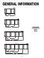
GENERAL INFORMATION
DESCRIPTION OF CASES: The refrigerated display cases described in this handbook
are part of the Hill PHOENIX, KATS design series. Specifically covered in this manual is
model KRZH reach-in freezer.
STORE CONDITIONS: Hill PHOENIX cases are designed to operate in an air conditioned
store with a system that can maintain 75OF (24OC) store temperature and 55 percent (maximum) relative humidity (CRMA conditions). Case operation will be adversely affected by
exposure to excessively high ambient temperatures and/or humidity.
REFRIGERATION SYSTEM OPERATION: Air cooled condensing units require ventilation for
efficient performance of condensers. Machine room temperatures must be a minimum of
65OF in winter and a maximum of 95OF in summer. Minimum condensing temperatures
should be no less than 70OF.
RECEIVING CASES: Examine fixtures carefully for shipping damage and shortages. For
information on shortages contact the Service Parts Department at 1-800-283-1109.
APPARENT DAMAGE: A claim for obvious damage must be noted on the freight bill or
express receipt and signed by the carriers agent, otherwise the carrier may refuse the claim.
CONCEALED DAMAGE: If damage is not apparent until after the equipment is unpacked,
retain all packing materials and submit a written request to the carrier for inspection within
15 days of receipt of equipment.
LOST ITEMS: This equipment has been carefully inspected to insure the highest level of
quality. Any claim for lost items must be made to Hill PHOENIX within 48 hours of receipt
of equipment.
TECHNICAL SUPPORT: If any technical questions arise regarding a refrigerated display
case contact our Customer Service Department in Richmond at 1-804-526-4455. For any
questions regarding our refrigeration systems or electrical distribution centers contact our
Customer Service Department in Conyers at 1-770-285-3200.
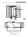
CONTACTING FACTORY: Should you need to contact Hill PHOENIX regarding a specific
fixture, be sure to know the case model number and serial number. This information is on
the serial plate located on the top flue panel of the case (see next page for details). Ask for
a Service Parts Representative at 1-804-526-4455.
2
ACCESS DOOR
REFRIGERATION CONNECTION
ELECTRICAL JUNCTION BOX
22 5/8 in
[57.4 cm]
PLENUM
EXTERNAL PLUMBING
COIL
13 1/16 in
[33.2 cm]
99 in
[251.5 cm]
100 15/16 in
[256.4 cm]
97 in
[246.5 cm]
66 3/8 in
[168.6 cm]
(Door Height)
94 7/16 in
[239.8 cm]
98 7/8 in
[251.2 cm]
Amp Plate & Serial
Plate Location
70 3/4 in
[179.7 cm]
88 7/8 in
[225.7 cm]
68 1/2 in
[174.0 cm]
(Frame Height)
83 7/8 in
[213.1 cm]
31 in
[78.7 cm]
38 3/8 in [98.3 cm]*
5 in [12.7 cm]
8 5/8 in
[22.0 cm]
40 1/8 in [101.9 cm]
2 13/16 in [7.1 cm]
42 7/16 in [107.8 cm]
MODEL
KRZH
44 5/8 in [113.3 cm]
EXTERNAL PLUMBING
19 5/8 in. [49.8 cm.] {2-DOOR}
34 5/8 in. [87.9 cm.] {3-DOOR}
49 5/8 in. [126.0 cm.] {4-DOOR}
64 5/8 in. [164.1 cm.] {5-DOOR}
11 7/16 in [29.1 cm]
2 13/16 in [7.1 cm]
20 3/4 in
[52.7 cm]
**
34 1/4 in
[87.0 cm]
10 in [25.4 cm]
REFRIGERATION
(TOP-REAR OF CASE)
7 13/16 in
[19.9 cm]
1 1/2" PVC DRAIN
CONNECTION
CL
FRONT OF CASE
60 in. [152.4 cm.] {2-DOOR}
90 in. [228.6 cm.] {3-DOOR}
120 in. [304.8 cm.] {4-DOOR}
150 in. [381.0 cm.] {5-DOOR}
NOTES:
* STUB-UP AREA
** RECOMMENDED STUB-UP CENTERLINE FOR ELECTRICAL AND HUB DRAINS
z
z
44 5/8 in
[113.3 cm]
42 7/16 in
[107.8 cm]
ELECTRICAL
(TOP OF CASE)
44 5/8 in
[113.3 cm]
39 1/8 in
[99.4 cm]
SUCTION LINE 7/8", LIQUID LINE - 1/2"
AVAILABLE SHELF SIZES: WIRE SHELVES 16", 18", 20", 22" & 23 1/2"
SOLID SHELVES 18", 20", 22", 24" & 27"
3
1 1/2 in [3.8 cm]
{END}
GENERAL INFORMATION
4"
2 DOOR CASE
36 1/2"
32 1/8"
59 1/4"
FRONT OF CASE
3 DOOR CASE
4"
36 1/2"
27 5/8"
57 5/8"
89 1/4"
BASEHORSE
LOCATION FOR
MODEL
KRZH
FRONT OF CASE
4"
4 DOOR CASE
36 1/2"
27 5/8"
62 1/8"
87 5/8"
119 1/4"
FRONT OF CASE
4"
5 DOOR CASE
36 1/2"
27 5/8"
57 5/8"
87 5/8"
117 5/8"
149 1/4"
FRONT OF CASE
4
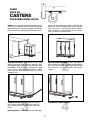
CASES
MOVE ON
CASTERS
FOR EASIER INSTALLATION
KATS cases are manufactured and shipped to stores
with casters installed on the base frame to make the
job of moving cases easier for everyone involved with
the manufacturing, shipping and installation process.
Casters not only speed up the process, but they also
reduce the chance of damage from raising and lowering cases with ”J” bar to place them on dollies,
skates or rollers. In most situations, one or two persons can move the case with ease.
1
ROLL TO LINEUP POSITION. Casters may remain in
place to move the cases to staging areas around the
store, prior to final installation. When ready for final
line-up, roll the case to set position, then remove
casters.
3
CASTERS MAY BE DISCARDED.
2
ROLL OUT OF TRUCK. When there is a truck - level
delivery dock (with 8’ ft. minimum opening), cases
may be rolled directly from the truck to the store floor.
[CAUTION] If skid boards are required to unload
cases, casters should be removed prior to sliding
them down the skid; after which they can be reinstalled on case.
4
REMOVE COTTER PIN. Removing the casters is
easy. Simply flatten and hammer out cotter pins
then lift the case with “J” bar, and the casters will
fall off.
[CAUTION] Make certain hands are out of the way.
5
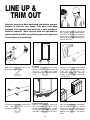
LINE UP &
TRIM OUT
Now that cases have been positioned and leveled, you may
proceed to trim-out case lineup. Trim parts have been
designed to be applied easily with only a small number of
fasteners required. Most external parts are adjustable to
achieve almost invisible, snug-fitting joints and a high level
of excellence in fit and finish.
BASE RAIL
Snap Chalk Lines
2
Mark floor where cases are to be
located for the entire lineup.
Set Shims On Basehorse Locations
5
Locate basehorse positions along chalk
lines.
Spot shim packs at each
basehorse location.
Consult With General Contractor
1
Ask the general contractor if there have
been changes in the building dimensions since the print you are using was
issued. Also, ask the points of reference
from which you should take dimensions
to locate the cases.
BASE RAIL
Snap Lines On Base Rail
Locations
Snap lines where base rails are positioned, not the front or back edges of
the cases. See case cross section
drawing, page 3, for rail location dimensions.
Level Floor. Use Laser Transit
Position First Case In Lineup,
Remove Casters, Level
Roll first case into position. Raise case
from end under cross support using
“J” bar. Remove cotter pins, casters,
and outriggers. [CAUTION! Keep hands
from under case] Level case on shims.
Position Next Case In Line Up
3
6
6
4
Leveling is necessary to assure proper
case alignment. Locate highest point on
chalk
line
as
reference
for
determining height of shim-pack
levelers. A laser transit is recommended for precision.
7
Roll case approximately 6’ from adjoining case. Remove casters on the end
nearest to the next case. Allow casters
to remain on opposite end to assist in
pushing cases together - then remove
them.
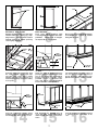
4
5
CAULK
CAULK
3
2
Remove Shipping Accessories
From Case. Add Sealant.
Remove anything from case that may
interfere with case joining (eg. shipping braces). Run a bead of sealant
around entire end before pushing
cases tightly together.
8
1
Bolt Cases Together Using Bolt
Holes Provided
Push cases tightly together. Bolt
cases together through the four holes
provided.
Tighten until all margins
are equal; do not over tighten.
9
Add Sealant to Top Case Joint.
10
Once cases are pushed tightly together
and bolted run a bead of sealant
along the top joint.
ACRYLIC
TAPE
TANK
UPPER
KICKPLATE
RETAINER
KICKPLATE
BRACKET
“J” RAIL
PIPE
CHASE
KICKPLATE
BRACKET
PEDESTAL
Caulk Pipe Chase, Install Acrylic Tape
Install Upper Kickplate Retainer &
“J” Rail
Attach the upper kickplate retainer by
placing it against the bottom of the tank.
Line up the retainer with the kickplate
bracket and attach with the screws
provided. Set the “J” rail flush to the
floor and attach it to the kickplate
bracket with the screws provided.
Install Pedestals
11 12 13
Seal joints along pipe chase seam with
the caulk provided. Apply acrylic tape
over pipe chase seam. Tape is found
with the ship loose items and acts as a
watershed preventing water from settling
in case joint.
UPPER
KICKPLATE
RETAINER
“J” RAIL
The pedestals line-up at the corner of
the case that is located at the end of a
line-up. Attach the pedestal to the kickplate bracket with the screws provided.
END
KICKPLATE
KICKPLATE
PEDESTAL
TRACK
BASEFRAME
Insert Kickplate
Install End Kickplate
BUMPER
TRIM
Install Bumper Trim
14 15 16
Insert top of kickplate into the upper
kickplate retainer. Slide the kickplate up
into retainer then down on the “J” rail.
End kickplates are installed only on
cases with ends. Fit the end kickplate
under the end and secure it to the baseframe.
7
Insert the bumper trim into the track that
is mounted to the front panel of the
case.
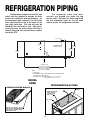
REFRIGERATION PIPING
The expansion valve and other
controls are located just under the top
access hatch. Pull open the hatch and lift off
the end evaporator cover on the left hand
side to access the refrigeration controls.
Refrigeration components and the coil
outlet hole are located to provide the best
access for installation and maintenance. As
the diagrams below indicates, the coil outlet
hole is positioned on top of the case on the
rear, right hand side. This hole will have be
drilled by the contractor on site. After penetrating the case top make certain the hole is
sealed afterward with canned-foam sealant
and white RTV.
10 in [25.4 cm]
20 3/4 in
[52.7 cm]
**
REFRIGERATION
(TOP-REAR OF CASE)
44 5/8 in
[113.3 cm]
42 7/16 in
[107.8 cm]
44 5/8 in
[113.3 cm]
1 1/2 in [3.8 cm]
{END}
CL
FRONT OF CASE
60 in. [152.4 cm.] {2-DOOR}
90 in. [228.6 cm.] {3-DOOR}
120 in. [304.8 cm.] {4-DOOR}
150 in. [381.0 cm.] {5-DOOR}
NOTES:
* STUB-UP AREA
** RECOMMENDED STUB-UP CENTERLINE FOR ELECTRICAL AND HUB DRAINS
z
z
SUCTION LINE 7/8", LIQUID LINE - 1/2"
AVAILABLE SHELF SIZES: WIRE SHELVES 16", 18", 20", 22" & 23 1/2"
SOLID SHELVES 18", 20", 22", 24" & 27"
MODEL
KRZH
REFRIGERATION ACCESS
REMOVE SHIPPING BLOCKS
TOP ACCESS
HATCH
EXPANSION VALVE AND
OTHER CONTROLS
LOCATED ON THIS
SIDE OF CASE
COIL OUTLET
REMOVE THE SHIPPING BLOCKS
THAT PROTECT THE REFRIGERATION
LINES DURING SHIPMENT BEFORE
OPERATING THE CASE.
8
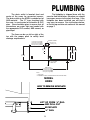
PLUMBING
The kickplate is shipped loose with the
case for field installation, therefore you should
have open access to the drain line area. If the
kickplate has been installed, you will find it
very easy to remove. See instructions below,
or the line-up and trim out section of this manual
on page 7.
The drain outlet is located front and
center of the cases for convenient access.
The drain outlet on the KRZH is molded out of
ABS material. The “P” trap, furnished with
the case, is constructed of schedule 40 PVC
pipe. Care should be given to assure that all
connections are water tight and sealed with
the appropriate PVC cement, ABS cement, or
pipe dope.
The lines can be run left or right of the
tee with the proper pitch to satisfy local
drainage requirements.
EXTERNAL PLUMBING
19 5/8 in. [49.8 cm.] {2-DOOR}
34 5/8 in. [87.9 cm.] {3-DOOR}
49 5/8 in. [126.0 cm.] {4-DOOR}
64 5/8 in. [164.1 cm.] {5-DOOR}
11 7/16 in [29.1 cm]
2 13/16 in [7.1 cm]
20 3/4 in
[52.7 cm]
**
39 1/8 in
[99.4 cm]
44 5/8 in
[113.3 cm]
42 7/16 in
[107.8 cm]
44 5/8 in
[113.3 cm]
1 1/2" PVC DRAIN
CONNECTION
CL
FRONT OF CASE
60 in. [152.4 cm.] {2-DOOR}
90 in. [228.6 cm.] {3-DOOR}
120 in. [304.8 cm.] {4-DOOR}
150 in. [381.0 cm.] {5-DOOR}
NOTES:
* STUB-UP AREA
** RECOMMENDED STUB-UP CENTERLINE FOR ELECTRICAL AND HUB DRAINS
MODEL
KRZH
HOW TO REMOVE KICKPLATE
LIFT UP FROM “J” RAIL
AND PULL OUT
KICKPLATE
“J” RAIL
9
1 1/2 in [3.8 cm]
{END}
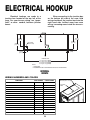
ELECTRICAL HOOKUP
Electrical hookups are made to a
junction box located at the top, left of the
case. For case-to-case wiring, run “greenfield”, or other conduit, between junction
boxes.
When connecting to the junction box
on the bottom left side of the case, field
wiring should exit the junction box from the
right hand side, furthest away from case
wiring, increasing room inside for wire connecting.
20 3/4 in
[52.7 cm]
**
34 1/4 in
[87.0 cm]
44 5/8 in
[113.3 cm]
42 7/16 in
[107.8 cm]
ELECTRICAL
(TOP OF CASE)
44 5/8 in
[113.3 cm]
1 1/2 in [3.8 cm]
{END}
7 13/16 in
[19.9 cm]
CL
FRONT OF CASE
60 in. [152.4 cm.] {2-DOOR}
90 in. [228.6 cm.] {3-DOOR}
120 in. [304.8 cm.] {4-DOOR}
150 in. [381.0 cm.] {5-DOOR}
NOTES:
* STUB-UP AREA
** RECOMMENDED STUB-UP CENTERLINE FOR ELECTRICAL AND HUB DRAINS
MODEL
KRZH
WIRING NUMBERS AND COLORS
COMPONENT
EVAPORATOR FANS, 120 VOLT
DOOR & FRAME ANTI-COND. HEATERS, 120 VOLT
LIGHTS, 120 VOLT
ANTI-CONDENSATE HEATERS, 120 VOLT
TEMPERATURE CONTROL, 120 VOLT
WIRE NUMBER
COLOR CODING
3
WHITE
4
BLACK
15
WHITE
16
BLACK
11
WHITE
12
BLACK
13
WHITE
14
BLACK
19
YELLOW
20
YELLOW
DEFROST TERMINATION CONTROL, 120 VOLT
21
PURPLE
23
ORANGE
DEFROST HEATERS, 208/240 VOLTS
L1
RED
EQUIPMENT GROUNDING CONDUCTOR
L2
BLUE
-
GREEN
10
ELECTRICAL ACCESS HOLE
(Drilled through rear of case)
TOP ACCESS
HATCH
BALLASTS ACCESS
The electronic ballasts that operate the vertical prism door lights are located in the door frame for
both Ardco® and Anthony®.
DOOR FRAME
PRISM LIGHT
ARDCO®
1. BALLAST COVER
SCREWS
2. BALLAST COVER
3. BALLAST CARRIAGE SCREWS (2) ARE
LOCATED BEHIND BALLAST COVER.
4. ONCE BALLAST CARRIAGE SCREWS ARE
REMOVED PULL OUT THE CARRIAGE AND
REPLACE THE BALLAST.
LIGHT
MULLION
3. BALLAST
1. CORNER BEAD
1. CORNER BEAD
STEPS TO REPLACE THE BALLAST
ARDCO®
1. REMOVE SCREWS IN BALLAST COVER
2. REMOVE BALLAST COVER
3. REMOVE SCREWS IN BALLAST
CARRIAGE
4. REPLACE BALLAST
ANTHONY®
2. ACCESS COVER
1. REMOVE CORNER BEADS (2)
2. REMOVE ACCESS COVER
3. REPLACE BALLAST
DOOR
ANTHONY®
11
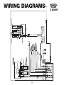
WIRING DIAGRAMS-
12
MODEL
KRZH
2 DOOR
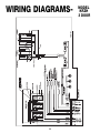
WIRING DIAGRAMS-
13
MODEL
KRZH
3 DOOR
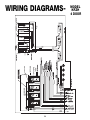
WIRING DIAGRAMS-
14
MODEL
KRZH
4 DOOR
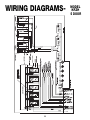
WIRING DIAGRAMS-
15
MODEL
KRZH
5 DOOR
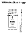
WIRING DIAGRAMS-
16
TERMINAL
BLOCK
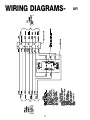
WIRING DIAGRAMS-
17
GFI
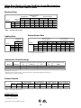
Glass Door Reach-in Frozen Food/Ice Cream Merchandiser
KRZH - 2, 3, 4 & 5-door reach in freezer
Electrical Data
Model
KRZH
1
Standard Fans
Anti-Condensate
Heaters
120 Volts
120 Volts
Drain Pan Heaters
208 Volts
240 Volts
Fans per
Case
Amps
Watts
Amps
Watts
Amps
Watts
Amps
Watts
2
3
4
5
2.20
3.30
4.40
5.50
167
250
333
417
6.06
8.48
10.82
12.88
727
1018
1298
1545
0.86
0.86
0.86
0.86
179
179
179
179
0.99
0.99
0.99
0.99
238
238
238
238
2-door
3-door
4-door
5-door
NOTE: - - - not an option on this case model.
Defrost Heater Data
Lighting Data
Model
KRZH
2-door
3-door
4-door
5-door
Defrost Heaters2
Hot Gas Defrost
240 Volts
208 Volts
Maximum
Lighting
120 Volts
Amps Watts
1.88
226
2.50
300
3.13
376
3.75
450
Model
KRZH
2-door
3-door
4-door
5-door
Defrost Heaters
Electric Defrost
208 Volts
240 Volts
Amps
Watts
Amps
Watts
Amps
Watts
Amps
Watts
1.92
1.92
1.92
2.40
400
400
400
500
2.22
2.22
2.22
2.78
533
533
533
666
5.77
7.69
12.02
15.39
1200
1600
2500
3200
6.66
8.88
13.87
17.75
1593
2128
3355
4260
2Note: Hot gas defrost requires electric assist heaters.
Guidelines & Control Settings
Discharge Air
(oF)
Return Air
(oF)
Discharge Air Velocity5
(FPM)
3-5
-8
-3
420
3-5
-12
-7
420
Evaporator Superheat Set Point
@ Bulb (oF)
(oF)
Model
BTUH/door4
KRZH - F3
1850
-12
KRZH - C3
2200
-22
3
F = Frozen food, C = Ice cream.
4
BTUH's/door listed are for parallel operation. Conventional ratings may be approximated by multiplying listed rating by 1.04.
5
Average discharge air velocity at peak of defrost.
Defrost Controls
Electric Defrost
Model
KRZH
6
Defrosts Run-Off
Per Day Time (min)
1
13 - 15
Timed Off Defrost
60
73
- - -6
---
NOTE: - - - not an option on this case model.
Low Temperature Defrost Schedule
No. Per Day
1
2
Hot Gas Defrost
Reverse Air Defrost
Fail-safe Termination Fail-safe Termination Fail-safe Termination Fail-safe Termination
(min)
Temp. (°F)
(min)
(min)
(min)
Temp. (°F)
Temp. (°F)
Temp. (°F)
Hours
10 pm
6 am - 10 pm**
** Or immediately after store closing hour
All measurements are taken per CRMA specifications.
COMPONENT
18
24
73
---
---
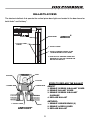
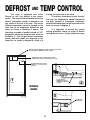
DEFROST AND TEMP CONTROL
This case is equipped with either
Electric or Hot Gas defrost at the owners
option. The sensor bulb and probe for electric
defrost termination control is located on the
top, center of the coil at the rear. The sensor
bulb for temperature control is located on the
right side of the evaporator behind the end
cover, as shown in illustration 1 below. The
discharge air probe is located behind a 3 1/2”
plug button on the top flue panel also shown in
illustration 1. The hot gas defrost termination
sensor bulb and probe are attached to the
dump line, as shown in diagram 2, which is in
the top, left hand side of the case.
The defrost termination control thermostat and the temperature control thermostat
are both located in thermostat enclosures
behind the kickplate on the left hand side of the
case, as shown in diagram 3.
It is important to consult the control
setting guidelines shown on page 18 before
setting defrost times. Further adjustment may
PLENUM
• ELECTRIC DEFROST TERMINATION CONTROL SENSOR BULB LOCATION
• ELECTRIC DEFROST TERMINATION PROBE LOCATION
COIL
• TEMPERATURE CONTROL SENSOR BULB LOCATION
(UNDER ACCESS HATCH ON EXITING AIR SIDE OF COIL).
DISCHARGE AIR PROBE LOCATION
(BEHIND 3 1/2” PLUG BUTTON IN
TOP FLUE).
1
HOT GAS DEFROST
TERMINATION CONTROL
SENSOR BULB AND PROBE
LOCATION.
2
MODEL
KRZH
3
THERMOSTAT
ENCLOSURE
19
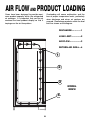
AIR FLOW AND PRODUCT LOADING
Cases have been designed to provide maximum product capacity within the refrigerated
air envelope. It is important that you do not
overload the food product display so that it
impinges on the air flow pattern.
Overloading will cause malfunction and the
loss of proper temperature levels, particularly
when discharge and return air sections are
covered. Please keep products within the load
limit line shown on the diagram.
DISCHARGE..............1
LOAD LIMIT...............2
AIR FLOW..................3
RETURN AIR GRILL...4
1
2
3
MODEL
KRZH
4
20
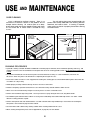
USE AND MAINTENANCE
CASE CLEANING
Case is designed to facilitate cleaning. There is no
mechanical or electrical controls in the product area to
hamper routine cleaning. All surfaces pitch to a deepdrawn drain trough that angles toward the front and center
of case where the 2” waste outlet is located for easy
access.
The coil and fan plenum are located outside the
product area to keep food fluids from entering, diminish
downtime, and reduce shrink. If cleaning is required,
make certain fan plenum is properly closed after cleaning
to avoid air leaks.
HONEYCOMB
LIFT UP TOP
HATCH TO EASILY
ACCESS COIL
AND PLENUM
REAR
HONEYCOMB
RETAINER
TOP HATCH
SCREW
LOOSEN SCREWS IN
REAR HONEYCOMB
RETAINER AND
TWIST HONEYCOMB
OUT
POSITIVE DRAIN OFF
COIL CLEANING
CLEAN HONEYCOMB
CLEANING PROCEDURES
• A periodic cleaning schedule should be established to maintain proper sanitation, insure maximum operating efficiency, and
avoid the corrosive action of food fluids on metal parts that are left on for long periods of time. We recommend cleaning once
a week.
• To avoid shock hazard, be sure all electrical power is turned off before cleaning. In some installations, more than one
disconnect switch may have to be turned off to completely de-energize the case.
• Check waste outlet to insure it is not clogged before starting the cleaning process and avoid introducing water faster than the
case drain can carry it away.
• Avoid spraying cleaning solutions directly on fans or electrical connections.
• Provide a temporary separator between those cases which are being cleaned and those which are not.
• Allow cases to be turned off long enough to clean any frost or ice from coil and flue areas.
• Remove and clean discharge honeycomb. You may need to use spray detergent and a soft, long bristle brush.
• Use mild detergent and warm water. When necessary, water and baking soda solution will help remove case odors. Avoid
abrasive scouring powders or pads.
• Remove front panels and clean underneath the case with a broom and a long handled mop. Instructions for removing the
front panels can be found on page 6 of this manual.
• Use warm water and a disinfecting cleaning solution when cleaning underneath the cases.
• When cleaning antifog doors please refer to Appendix A, on page 26, for more details.
21
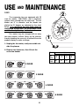
USE AND MAINTENANCE
FANS
2
The evaporator fans are equipped with 25
watt fan motors, 1550 RPM’s, with a clockwise
rotation when viewed from the shaft end. The fan
blades are 8” in diameter and the blades are
pitched to 31 degrees as indicated on the chart
below. It is important that the blade pitch be
maintained as specified. Do not attempt a field
modification by altering the blades.
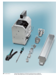
Fan motors may be changed with an easy
two-step process without lifting up the plenum,
thereby avoiding the necessity to unload the entire
product display to make a change:
1
1. Unplug the fan motor, easily accessible out
side the plenum
2. Remove two fasteners, then lift out the
entire fan basket
Model
No.
Fans
Blade
Pitch
KRZH
2 Door 3 Door 4 Door 5 Door
3
2
o
31
31
2 DOOR
3 DOOR
4 DOOR
5 DOOR
22
4
o
5
o
31
o
31
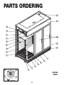
PARTS ORDERING
Procedure
1. Contact the Service Parts Department
Hill PHOENIX
1925 Ruffin Mill Road
Colonial Heights, Virginia 23834
Tel: 800-283-1109
Fax: 804-526-3897
2. Provide the following information about the part you are ordering:
• Model number and serial number of the case on which
the part is used.
• Length of part, if applicable, I.E. 60”, 90”, 120”, or 150”.
• Color of part if painted, or color of polymer part.
• Whether part is for left hand or right hand application.
• Whether shelves are with or without lights.
• Quantity
*Serial plate is located on top flue panel on the left hand side of the
case (See illustrations on page 3).
3. If parts are to be returned for credit, ask the Parts Department to
furnish you with a Return Materials Authorization Number.
23
PARTS ORDERING
23
19
69
25
13
55
12
22
87
36
88
82
15
9
4
17
56
11
1
24
E09
E10
81
MODEL
KRZH
E20
E11
24
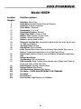
Model KRZH
Location
Number
1
4
9
11
12
13
15
17
19
22
23
24
25
36
55
56
69
81
82
87
88
E01
E02
E09
E10
E11
E20
Part Descriptions
Kickplate, Storm Grey
Color Band, Painted Custom Color or Stainless
Deck Pan, Painted, Unpainted
Front Baffle, Aluminum
Honeycomb, 1”x 4”x 48”
Honeycomb Retainer, Painted
Upper Rear Baffle, Center or End
Bumper Trim, Polymer Custom Color
Cornice, Painted Custom Color
Shelves, Specify Solid or Wire
Electrical Junction Box, (mounted on bottom left front or on top left rear)
“J” Rail, for Kickplate
Top Flue Panel, Painted
Plug Button, White or Black
Door, Specify Mask Color, Ardco or Anthony, Door Handle Type, Low or
Medium Temperature Application, Left or Right Hand Swing
Door Frame, Ardco or Anthony, Low or Medium Temperature Application
Coil
Bottom Wire Racks
Tag Moulding, PVC or Aluminum
End Assembly, Solid, Custom Color, Identify Left or Right hand, Color of
Panel, and Color of End Trim Color
End Kickplate, Painted, Stainless Steel
Defrost Heaters (Not Shown)
Anti-Condensate Heaters (Not Shown)
Fan Motor - STATE HIGH EFFICIENCY OR STANDARD
Fan Blade
Fan Basket, 8”
Fan Cord-Set, High Efficiency or Standard
25
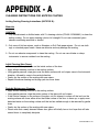
APPENDIX - A
CLEANING INSTRUCTIONS FOR ANTIFOG COATING
Antifog Coating Cleaning Instructions (ANTIFOG B):
Materials
CAUTION:
1. Only use deionized or distilled water with 2% cleaning solution (P/N 05-14700-0001) to clean the
antifog coating. Do not apply cleaning solution full strength! Do not use commercial glass
cleaners containing ammonia or alcohol.
2. Only use soft lint-free wipers, such as Kimwipes or Soft-Tech paper wipers. Do not use cloth
rags or standard paper towels--these are abrasive and may damage the coating.
3. Do not use abrasive compounds to clean the coating. Do not use razor blades or sharp
instruments to remove residue from the coating.
Initial Cleaning (New Doors)
• Remove protective plastic film on the inside surface of the door.
• Apply diluted cleaning solution to the coating surface.
• Using gentle pressure, wipe glass over the entire surface with soft wipers once in the horizontal
direction, followed by once in the vertical direction.
• Gently dry the surface of the coating with new wipers.
• Repeat the above cleaning and drying cycle two more times.
Periodic Maintenance Cleaning
• Apply diluted cleaning solution to the coating surface.
• Using gentle pressure, wipe the entire surface of the glass with soft wipers.
• If the solution freezes on the surface of the glass, do not attempt to scrape off the ice from the
coating surface with force; either allow the inside surface of the door to warm up, or apply more
deionized water on the coating surface until the ice has melted enough to be removed by gentle
force.
• Gently dry the surface of the coating with new wipers.
• Please note that a newly cleaned freezer door glass will initially form a frost layer that will take
several hours to completely dissipate.
06-14654-0000 Rev X4
26
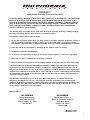
WARRANTY
HEREINAFTER REFERRED TO AS MANUFACTURER
FOURTEEN MONTH WARRANTY. MANUFACTURER’S PRODUCT IS WARRANTED TO BE FREE FROM
DEFECTS IN MATERIAL AND WORKMANSHIP UNDER NORMAL USE AND MAINTENANCE FOR A
PERIOD OF FOURTEEN MONTHS FROM THE DATE OF ORIGINAL SHIPMENT. A NEW OR REBUILT
PART TO REPLACE ANY DEFECTIVE PART WILL BE PROVIDED WITHOUT CHARGE, PROVIDED THE
DEFECTIVE PART IS RETURNED TO MANUFACTURER. THE REPLACEMENT PART ASSUMES THE
UNUSED PORTION OF THE WARRANTY.
This warranty does not include labor or other costs incurred for repairing, removing, installing, shipping,
servicing, or handling of either defective parts or replacement parts.
The fourteen month warranty shall not apply:
1. To any unit or any part thereof which has been subject to accident, alteration, negligence, misuse or
abuse, operation on improper voltage, or which has not been operated in accordance with the
manufacturer’s recommendation, or if the serial number of the unit has been altered, defaced, or removed.
2. When the unit, or any part thereof, is damaged by fire, flood, or other act of God.
3. Outside the continental United States.
4. To labor cost for replacement of parts, or for freight, shipping expenses, sales tax or upgrading.
5. When the operation is impaired due to improper installation.
6. When installation and startup forms are not properly complete or returned within two weeks after startup.
THIS PLAN DOES NOT COVER CONSEQUENTIAL DAMAGES. Manufacturer shall not be liable under any
circumstances for any consequential damages, including loss of profit, additional labor cost, loss of
refrigerant or food products, or injury to personnel or property caused by defective material or parts or for
any delay in its performance hereunder due to causes beyond its control. The foregoing shall constitute
the sole and exclusive remedy of any purchases and the sole and exclusive liability of Manufacturer in
connection with this product.
The Warranties are Expressly in Lieu of All Other Warranties, Express of Implied and All Other
Obligations or Liabilities on Our Part. The Obligation to Repair or Replace Parts or Components
Judged to be Defective in Material or Workmanship States Our Entire Liability Whether Based on Tort,
Contract or Warranty. We Neither Assume Nor Authorize Any Other Person to Assume for Us Any
Other Liability in Connection with Our Product.
MAIL CLAIM TO:
Hill PHOENIX
Hill PHOENIX
Display Merchandisers
1925 Ruffin Mill Road
Colonial Heights, VA 23834
804-526-4455
Refrigeration Systems &
Electrical Distribution Products
709 Sigman Road
Conyers, GA 30013
770-285-3200
6/00
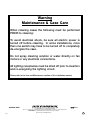
Warning
Maintenance & Case Care
When cleaning cases the following must be performed
PRIOR to cleaning:
To avoid electrical shock, be sure all electric power is
turned off before cleaning. In some installations, more
than one switch may have to be turned off to completely
de-energize the case.
Do not spray cleaning solution or water directly on fan
motors or any electrical connections.
All lighting receptacles must be dried off prior to insertion
and re-energizing the lighting circuit.
Please refer to the Use and Maintenance section of this installation manual.
804-526-4455
1925 Ruffin Mill Road, Colonial Heights, VA 23834
Due to our commitment to continuous improvement all specifications are subject to change without notice.
Hill PHOENIX is a Sustaining Member of the American Society of Quality.
Visit our web site at www.hillphoenix.com
ASH5011