1
Service & Installation Instructions
Keep this booklet for Future Reference
CDC SERIES
BMD CANDY SERIES
SMD CANDY SERIES
For Additional Copies Please Contact:
Hillphoenix Barker Specialty Products
703 Franklin Street
P.O. Box 478
Keosauqua, Iowa 52565
Tel: 319/ 293-3777
Fax: 319/ 293-3776
Or Visit:
www.hillphoenix.com
Updated 09/23/11
Table of Contents
General Information
Electrical Information
Case Descriptions - - - - - - - - - - - - - - - - - - - - -3
Shipping Information - - - - - - - - - - - - - - - - - - -3
Case Sections
CDC Candy Series - - - - - - - - - - - - - - - - - - -4
SMD Candy Series - - - - - - - - - - - - - - - - - - -4
Mechanical View - - - - - - - - - - - - - - - - - - - - - -4
Amperage Information - - - - - - - - - - - - - - - - -10
Wiring Color Code - - - - - - - - - - - - - - - - - - - -10
Ballast Information - - - - - - - - - - - - - - - - - - -10
Installation Instructions
Location - - - - - - - - - - - - - - - - - - - - - - - - - - - -5
Crate Removal - - - - - - - - - - - - - - - - - - - - - - -5
Drain, Electrical and Refrigeration
Connections for remote Cases - - - - - - - - - - - -5
Cases Exterior Loading - - - - - - - - - - - - - - - - -6
Leveling - - - - - - - - - - - - - - - - - - - - - - - - - - - -6
Joining Lineup - - - - - - - - - - - - - - - - - - - - - - -6
Doors - - - - - - - - - - - - - - - - - - - - - - - - - - - - - -6
Glass Adjustment - - - - - - - - - - - - - - - - - - - - -6
Shelving - - - - - - - - - - - - - - - - - - - - - - - - - - - -7
Installation Checklist - - - - - - - - - - - - - - - - - - -7
Cart Bumper Installation - - - - - - - - - - - - - - - -8
Maintenance Information
Cleaning - - - - - - - - - - - - - - - - - - - - - - - - - - -11
Light Bulb Replacement - - - - - - - - - - - - - - - -11
Load Limits - - - - - - - - - - - - - - - - - - - - - - - - -11
Service
Evaporator Coil Layout - - - - - - - - - - - - - - - -12
Compressor Layout Service Cases - - - - - - - -12
Preventative Maintenance - - - - - - - - - - - - - -13
Trouble Shooting Guide - - - - - - - - - - - - - - - -13
Service Department - - - - - - - - - - - - - - - - - - -14
Parts - - - - - - - - - - - - - - - - - - - - - - - - - - - - -14
Warranty - - - - - - - - - - - - - - - - - - - -15
Refrigeration Information
Case Operation - - - - - - - - - - - - - - - - - - - - - -9
Typical Component Settings - - - - - - - - - - - - -9
Refrigeration Loads - - - - - - - - - - - - - - - - - - - -9
Electronic Thermostat - - - - - - - - - - - - - - - - - -9
IMPORTANT!!
KEEP FOR FUTURE REF ERENCE
General Information
Shipping Information
This booklet contains information on:
IMPORTANT!
CDC SERIES
FOR YOUR PROTECTION PLEASE READ AND
OBSERVE THE FOLLOWING INSTRUCTIONS:
CDC-D
CDC-SC
CDC-R
Non-Refrigerated, 51" Service Candy
Case with Fixed Front Glass
Self-Contained, 51" Service Candy
Case with Fixed Front Glass
Remote, 51" Service Candy Case
with Fixed Front Glass
SMD CANDY SERIES
SMD-SD
SMD-SC
SMD-R
Candy Non-Refrigerated, 52" SelfService Candy Case with Spherical,
front lift glass
Candy Self-Contained, 49" SelfService Candy Case with Spherical,
front lift glass
Candy Remote, 49" Self-Service
Candy Case with Spherical, front lift
glass
The CDC Series conform to the following standards:
The SMD Candy Series conform to the following
standards:
Transportation companies assume all liability from
the time a shipment is received by them until the
time it is delivered to the consumer. Our liability
ceases at the time of shipment.
All shipments leaving our plant have been carefully
inspected. If a shipment arrives with the crating or
packaging damaged, have the carrier note the condition on the receipt. Check as soon as possible for
concealed damage.
If it is found that the shipment has been damaged
in transit, please DO NOT return it to us, but notify
and file a claim with the carrier at once. FAILURE
TO FOLLOW THIS PROCEDURE WILL RESULT
IN REFUSAL BY THE CARRIER TO HONOR ANY
CLAIMS WITH A CONSEQUENT LOSS TO THE
CONSUMER.
If a UPS shipment has been damaged, retain the
damaged material and the carton and notify us at
once. WE will file a claim.
GOODS SHOULD NOT BE RETURNED FOR
CREDIT UNLESS AUTHORIZED BY OUR SALES
DEPARTMENT.
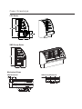
Case Drawings
CDC Series
SMD Candy Series
Mechanical Views
CDC Mechanical
SMD Candy Mechanical
Installation Instructions
ATTENTION INSTALLERS!!
Drain, Electrical and Refrigeration
Connections on Remote Cases
This candy case is not intended for the use with a
stepper valve or case controller. All control components are included by the case manufacture and
are pre-set. The CPC sensors supplied in this case
is for monitoring only.
Supply and install liquid / suction line connections
and power only.
If you have any questions please contact the service department at Barker Company 319-293-3777.
NOTE: Barker remote units are shipped with a
dry nitrogen charge of approximately 10 lbs.
pressure in the evaporator coil. During installation if nitrogen charge is not present, leak
check accordingly.
Location
This refrigerated display case has been designed
for displaying and the storage of perishable food
product. It is engineered for air-conditioned stores
with a maximum ambient of 75° F and 6% relative
humidity.
When selecting the location for placement of this
case, avoid the following conditions:
Excessive air movement
• Doors
• Air-conditioned vents
• Other air sources
Excessive heat
• Windows
• Sun
• Flood lamps 8 feet or less from the product
• Other heat sources
NOTE: A 12" clearance is necessary for condenser
coil to run correctly. Do not block.
Crate Removal
Move case as close as possible to its location.
Loosen the plastic dust cover from the pallet, but
leave cover over the case to protect it while removing the case from the pallet. Note: Locate horizontal
supports underneath the unit before removing from
pallet, damage to the finished metal will occur if correct lift points are not identified prior to removal.
Carefully lift case up and off pallet being careful that
leveling pads clear the pallet. Slide pallet from
under case. Shipping blocks are attached to pallet
and do not need to be removed.
1. See the mechanical views on Page 4 for drain
access locations. Connect the PVC drains (or the
copper drains) to existing floor drains. Traps are
installed at the factory within the case. ALL DRAINS
MUST BE TRAPPED. Provide as much downhill
slope as possible and avoid long runs of drain lines.
Do not install condensate drains in contact with
non-insulated suction lines in order to prevent condensate from freezing.
2. Electrical connections are made through the
power supply box of each case, which can be
accessed by removing the back panel. Voltage
requirements and component amperage can be
found in the electrical section of this manual, but
always check the data tag located on the exterior of
the case. CASE MUST BE GROUNDED.
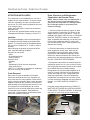
3. Refrigeration connections are made through the
refrigeration access cut out (see mechanical views).
See refrigeration information section of this manual
for caseloads and recommended settings.
Refrigeration lines may be headed together for all
cases in a lineup, if desired, by lines through the
access area under the case. Refrigeration lines
need to be connected in the lower refrigeration
compartment or through the toe kick area. Do not
run lines through the evaporator coil area shown to
the right. ALL LINES MUST BE CORRECTLY
SIZED.
For proper refrigeration performance, PRODUCT
MUST NOT BE PLACED IN A POSITION WHERE
IT MAY AFFECT THE AIR CURTAIN. Air discharge
and return air vents must remain unobstructed.
Case Exterior Loading
Doors
These cases are not designed for excessive external weight. DO NOT WALK ON TOP OF THE
CASE. Walking on top of cases could cause personal injury and damage to the case.
Rear doors are shipped inside the case. Push the
top of the doors all the way into top door tracks.
Push bottom of door over bottom door tracks and
lower over tracks. Doors are labeled inside and
outside for easy installation.
Leveling
To ensure proper operation of the refrigeration system and drainage of the condensate, THE CASE
MUST BE LEVEL. Use a carpenter level-to-level
front to back and side to side. Use the adjustable
leveling legs to level case.
Joining Lineups
1. Begin all lineups leveling from the highest point
of the store floor.
2. To access boltholes, remove outside back lower
panel, bottom deck, and top bolt cover located
in the canopy of the case.
3. Apply foam tape to facing ends of lineup. Level
second case to first case and seal with a good
grade silicone on all edges of each case.
4. Line up bottom bolt holes in lower front and
back of case (bolts are shipped in the case)
Slide cases together. Insert lower bolts and
place nuts on bolts. Tighten. THE FRONT OF
THE CASES MUST BE FLUSH!
5. Remove the top bolt cover, located in the
canopy of the case. Ensure that case is properly
leveled so that the bolt holes align over the bolt
holes in the adjoining case. Shim as necessary.
6. Tighten bolt in case top and replace bolt cover.
Ensure all bolts are fastened tightly.
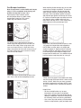
Glass Adjustment
The front lift glass on this case is installed at the
factory with the case perfectly level. If adjustments
need to be made to align the glass first check to
insure the case was properly leveled during installation.
NOTE: THIS IS A 2-PERSON OPERATION. ONE PERSON
MUST HOLD THE GLASS AT ALL TIMES.
1. Lift the glass to its highest position as shown in
drawing to the right.
2. Loosen allen screws. See profile left.
3. Slide glass right or left until the glass is even
and is recessed into the aluminum extrusion.
4. Tighten the right allen screw while holding the
left side of the glass firmly. Be careful to keep the
glass level.
5. Tighten the remaining allen screws.
6. Lower glass into position. Repeat as necessary
until glass is completely level.
Remove
access cover
Remove bot
tom shelf to
Lift hard
-
Remove
lower back
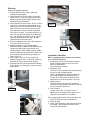
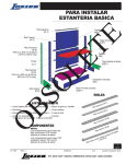
Shelving
Shelving is shipped separately.
1. Remove brackets, bars, lights, and/or tag
molding from packaging.
2. Insert brackets into Lozier channel at desired
height (Photo 1). Insert by angling up and then
down. Begin with bottom shelf brackets. Insert
middle and then top brackets.
3. Place support bars over screws. (Photo 2) There
may be 1 to 3 bars per shelf depending on the
width of the shelf. Fit from back of shelf to front.
Note: If fitting for wire shelves, some bars will
have clips on the center of the bar to hold the
wire shelves in place. For shelves less than 18"
wide, the clip should be placed in the back position. For shelving more than 18" wide, the clip
should be positioned in the middle. All clips
should face the back of the case.
4. Place tag molding on the front of the brackets in
the same manner as the bars.
5. Undershelf lights are not interchangeable.
Determine bottom, middle and top light by lining
up lights by cord length. Place longest cord
length on bottom shelf, middle length on middle
shelf and shortest cord on top shelf. Place light
over brackets and behind the tag molding as
shown (Photo 3).
6. Plug in lights. (Photo 4) Plug must be fully
seated for lights to work. If one plug is loose, all
lights will fail. Place cord in clip on bracket.
7. Place glass shelving on shelf brackets and bars.
If wire shelves are used, place shelf over clip to
hold in place.
Photo 1
Photo 3
Photo 4
Installation Checklist
Before supplying electrical power and starting
case check the following:
1. Compressor Area (For Self-contained cases).
Remove shipping block on units with semihermetic compressors.
Check location of controls.
2. Evaporator Area.
Check to ensure evaporator fan pressure plates
are secure and in proper position
NOTE: Hinged portion of pressure plates are
secured for shipping with mounting screws.
Screws do not have to be removed for case
operation but must be removed to use hinge.
3. Lighting System
Check to ensure male plugs are completely
inserted in female sockets and that all lamps are
securely seated in light fixture.
4. Case Leveling
Visually check case. If lift glass is out of
adjustment or case looks out of square, use a
carpenter's level and shim as needed.
After supplying power to the case and starting unit:
1. Check to ensure all fans are operational.
2. Check all lights.
3. Check case temperature and adjust thermostat
as needed. See refrigeration section of this
manual for case settings.
Photo 2
Cart Bumper Installation
Note: If equipment is ordered with cart bumper,
steps 1 & 2 are completed at the factory and
installer should skip to steps 3 & 4.
Tools required: Tape measure, pencil,
drill with phillips driver bit, rubber mallet,
straight edge, chalk line, PVC cutters,
cotton rags, non-abrasive cleaner
Cut plastic base to desired length of fixture.
When using end caps be sure to cut base 3/4”
short of fixture edge. When using corners, be
sure to cut base so that it is flush with fixture
edge. secure base to fixture with screws every 4”
on center. Make sure to put a screw 3/8” away
from the cut end of base.
SNAP end caps or corners onto the base extrusion. Secure with #8 flat head phillips screws.
When installing flexible bumper top, the cut ends
need to be as straight as possible. To mount on
a curved or flat surface, start at one end and
attach bumper to base by hooking bumper top
onto track, then snap bottom portion into place
and slide bumper against the end cap for a flushfit. Continue to hook bumper onto base track with
your hand or using a rubber mallet until you
reach other end cap. NOTE: Cover mallet with a
cloth to prevent marring the bumper finish.
Mark and cut tail end of flexible bumper at least
1/8” longer then beyond the end cap position.
NOTE: Make sure the end cut is straight and
square for proper fit. Slightly retract the bumper
in order to feed cut end into the end cap as you
finish hooking the top and bottom edges of the
bumper onto the base track. You should feel and
hear the bumper snap into place for a snug fit.
Finally, check for proper fit and attachment along
the entire length of bumper which is either on the
wall or a fixture. Make sure you have a smooth
and flush fit against the end caps. NOTE: Clean
any dust or debris with a cloth and non abrasive
cleaner.
Helpful Hints:
• Set the uncoiled flexible vinyl at room
temperature 24 hours prior to installation.
• Over cut the flexible vinyl and compression fit.
Adding the additional material will compensate
for stretching which occurs during installation.
• Use a clean, dry cloth and any mild household
cleaner or soap solution; spray and wipe clean
Refrigeration Information
Case Operation
Refrigeration
The thermostat closes at a plenum temperature of
55° degrees, if the humidistat is open the unit refrigerates until the plenum temperature reaches 50°
degrees.
{65 degree case temperature} and the thermostat
opens. If the humidistat is closed when the thermostat closes the humidistat energizes a heater coil
forcing the refrigeration unit to run until the desired
humidity level is reached.
On remote units a safety thermostat is wired inline
with the heater coil to prevent the heater from energizing if the unit is connected to a system that has
a defrost.
Typical Component Settings
1. Thermostat cut out: 50°, 5° differential
2. Humidistat
Programming Steps for the ETC, Electronic
Temperature Control
All thermostats are pre-set and cycle checked at
the factory.
50% or less
3. Evap Temperature: 45°
4. EPR valve:
45° Saturated Evap. Temp
5. TXV:
8-10° Superheat
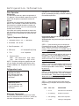
6.
(see photo 2). The thermostat is equipped with a
liquid crystal display providing a constant readout of
the sensed temperature.
Pressure switch:
404A
Low - 80 lb/ 110 lb
134A
Low - 33 lb/ 45 lb
High - 350 lb
High - 225 lb
NOTE: The above settings are approximate and
will vary slightly with product load, lighting, store
ambient conditions, etc. Evaporator fans run constantly.
Refrigeration Loads
CDC Service Series
BTU: 450 per linear foot
Evap. Temperature: +45°
No Defrost
SMD Candy Series
BTU: 450 per linear foot
Evap. Temperature: +45°
No Defrost
Electronic Thermostat
The electronic thermostat is located in the inside
back of a self-service case (see photo 1) and in the
rear lower refrigeration area in a service case
STEP 1: Press the set key once to access the
Fahrenheit/Celsius mode. The display will display
either F degrees Fahrenheit or C for degrees
Celsius. Press the up arrow or the down arrow so
the display indicates F.
STEP 2: Press the set key again to gain access to
the setpoint. The LCD will display the current
Setpoint and the S1 will be blinking. Press the up
arrow to increase or the down arrow to decrease
the temperature setting.
STEP 3: Press the set key again to gain access to
the differential. The LCD will display the current differential and the DIF 1 will be blinking. This should
be set at 2°F.
STEP 4: Press the set key again to gain access to
the cooling or heating mode. The LCD will display
the current mode. Press either the up arrow or the
down arrow to set the display in the C1, cooling
mode.
STEP 5: Press the set key once more and the
programming is complete. Set the lock to keep the
set point.
STEP
DISP. IND.
DESCRIPTION
1.
F or C
Fahrenheit or Celsius Scale
2.
S1 (blinking)
Setpoint Temperature
3.
DIF (blinking)
Differential Temperature
4.
C1/H1
Cooling or Heating Mode
Electrical Information
Remote Case Data - Electrical 120 Volt
Model
BTU Lin/Ft
Additional Loads for Self-Contained Units
Evap Temp
Evap Fans
Cornice Lts
Shelf Lts
HP
Voltage
134A
RLA/LRA
Cond Fan
Pan Heater
Heater
+45o
+45o
+45o
+45o
+45o
+45o
+45o
0.8
0.8
1.6
1.6
3.2
0.8
0.8
NA
NA
NA
NA
NA
NA
NA
0.95
0.95
1.54
1.9
1.9
0.95
0.95
1/4
1/4
1/3
1/2
1/2
NA
NA
120-1-60
120-1-60
120-1-60
120-1-60
120-1-60
120-1-60
120-1-60
3.9/25
3.9/25
5.6/29
6.8/36
9.2/45
NA
NA
0.56
0.56
0.72
0.7
0.68
NA
NA
6.6
6.6
6.6
6.6
6.6
NA
NA
1.375
1.67
2.0
2.5
3.34
1.375
1.375
+45o
+45o
+45o
+45o
+45o
+45o
+45o
0.43
0.43
0.86
0.86
1.29
0.43
0.43
0.76
0.95
0.95
1.54
1.54
0.49
0.49
0.75
0.95
1.8
1.8
2.85
0.49
0.49
1/4
1/3
1/2
1/2
1/2
NA
NA
120-1-60
120-1-60
120-1-60
120-1-60
120-1-60
120-1-60
120-1-60
3.9/25
5.6/29
6.8/36
9.2/45
9.1/51
NA
NA
0.56
0.72
0.7
0.68
1.4
NA
NA
6.6
6.6
6.6
8.3
8.3
NA
NA
1.375
2.0
2.5
3.34
4.0
1.375
1.375
SERVICE CDC SERIES
CDC-48
650
CDC-59
650
CDC-77
650
CDC-96
650
CDC-120
650
CDC-EW
1300*
CDC-IW
1300*
*BTU/Wedge
SMD CANDY SERIES
SMD-4
650
SMD-6
650
SMD-8
650
SMD-10
650
SMD-12
650
SMD-EW
650
SMD-IW
650
DRY CASES - USE LIGHTING SPECIFICATIONS FROM REMOTE CASE DATA
Wiring Color Code
Green------------------------Ground
Black-------------------------Hot
White ------------------------Neutral
Red --------------------------208/220 Only
Brown -----------------------Interlock System
Orange ----------------------Thermostat
Orange ----------------------Liquid Solenoid
Gray -------------------------Light Switch
Black/White ----------------Pressure Switch
Ballast Wiring
Red ----------Lights
Yellow -------Lights
Blue----------Lights
SEE BALLAST DIAGRAM
FOR EACH CASE
NOTE: Case must be grounded
Ballast Information
Model
Ballast Type Model
Ballast Type
CDC-48
(1) 4P
SMD-4
(2) 2P
CDC-59
(1) 4P
SMD-6
(2) 2P
CDC-77
(2) 3P
SMD-8
(2) 4P
CDC-96
(2) 4P
SMD-10 (2) 3P + (1) 4P
CDC-120 (2) 4P
SMD-12 (2) 4P
Maintenance Information
Cleaning
Case Exterior
Clean surfaces frequently with warm water and mild
detergent. Do not use strong alkali solutions, steel
wool, or abrasive cleansers.
Non-Glare Glass
Non-glare glass surfaces are coated to reduce the
glare from lighting. Care must be taken not to
scratch the coating. Use the following products only.
Cleaning Cloths
Scotch-Brite® High Performance Cloth - manufactured by 3M® and available in most grocery
stores under the name Scotch-Brite® Microfiber
Cleaning Cloth in a 12" x14" size. This cloth is
washable and may be reused as long as it remains
clean.
Spontex® Microfibre Cleaning Cloth - distributed
by Spontex® and available in most grocery stores
under the same name in a 15.75" x 12" size. This
cloth is washable and may be reused as long as it
remains clean.
The cleaning cloths named above will normally
remove dust, grease, oil and fingerprints without the
need for cleaning fluids. A light spray of the cleaning fluids listed below will reduce the time required
for cleaning.
Cleaning Fluid - for more difficult cleaning jobs,
these products are recommended:
Windex® - standard product only (extrastrength or specialty products may not be
suitable)
Glass-Plus® - standard product only
(extra-strength or specialty products may
not be suitable)
Warm Water
DO NOT USE the following types of materials for
cleaning glass with anti-reflective coatings.
Coarse Paper Towels
Scouring Pads or Powders
Steel wool or Steel Fiber Materials
Blades
Acidic or highly Alkaline detergents
Fluorine based detergents
Plexiglas
Use Novus® 1 and Novus® 2 to clean. Use
Brillianize® to polish. Contact factory to order. DO
NOT use strong alkali solutions, steel wool, or abrasive cleansers.
Evaporator Coil
Clean as needed.
Condenser Coil
Clean condenser coil every three months or as
needed with a whisk broom or vacuum. DISCONNECT POWER WHEN SERVICING. FINS ON
CONDENSER COIL ARE SHARP!
Condensate Heater
Add scale remover to condensate heater pan once
every three months or as needed. Heater is
designed for 75° and 50% relative humidity. The
condensate pan may overflow if design limits are
exceeded.
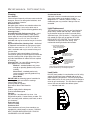
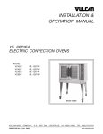
Light Replacement
The fluorescent lights in this case are furnished with
plastic safety shields and end caps. When replacing fluorescent lamps, be certain to reinstall safety
shield and caps. (See illustration). If the bulb is not
fully seated the lights will not operate. BE SURE
BULBS ARE FULLY SEATED. The light switch is
mounted to the right side of the ceiling. See
mechanical drawing for ballast box location.
A. To remove bulb, grasp lamp
holder on either end of the bulb
and with equal pressure pull
down.
B. Install new bulb into the
plastic safety tube protector.
Insert bulb into end cap.
lamp holder
cap
bulb in safety tube
C. Position the bulb and cap
under the lamp holder
and with even pressure
press the bulb into the
light fixture.
Caution: Failure to install bulb fully into light socket will cause
premature bulb life and may cause damage to light fixture
Load Limits
DO NOT place product in merchandisers until all refrigeration controls have been adjusted and are at the
proper operating temperature. DO NOT place product
above load limits or in such a way that the discharge or
return air grill are blocked. This will effect the performance of the case and effect the defrost system.
-------- Indicates load limit.
Service
WARNING!
DISCONNECT THE ELECTRICAL POWER WHEN SERVICING OR REPLAC
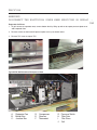
Evaporator Coil Area
1. To gain access to evaporator area, remove bottom deck by lifting up and out to expose pressure plate cover
and evaporator fans.
2. Remove screws as shown and lift pressure plate cover up as shown below.
3. Remove TXV cover to expose TXV.
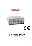
Typical CDC Self-Contained Compressor Area
B.
H.
E.
I.
D.
F.
A.
A.
B.
C.
Dissipater Pan
Ballast Box
Junction Box
J.
G.
C.
D. Compressor
E. Receiver
F. Thermostat
G. Pressure Switch
H. Filter Drier
I.
Site Glass
J. Coil
ING
Preventative Maintenance
1.
2.
3.
Read the installation and Service manual.
See the trouble-shooting guide in the event of problems.
Contact Barker Company for an authorized service person in your area.
Service Department - (319) 293-3777
Trouble Shooting Guide
Problem:
Action
Case temperature is too warm.
Case is in defrost. Review T-State Settings
Product load may be over its limits
Check case position in store. Ambient conditions may
be affecting the case operation.
Case temperature is too cold.
The T-Stat Temp is set too low.
Check case position in the store. Ambient conditions
may be affecting the case operation.
Case has condensation on glass.
Check grill on die board for adequate airflow over the
glass.
Product load may be over its limits
Check case position in the store. Ambient conditions
may be affecting the case operation.
Water has pooled under the case.
Check the floor drain for clogs.
check PVC drains under case for leaks.
check condensate pan for malfunctioning parts. Check
float, element, and switch.
Airflow is limited.
Product load may be restricting air flow.
Check evaporator fans. Iced evaporator may impede
airflow. Proximity to air ducts, opening window and
doors may cause airflow to be disrupted.
Self-Contained case makes excessive noise.
Check to make sure that the shipping block under the
compressor has been removed. Check that compressor mounting screws are not tight.
Refrigerant leak
Check to make sure that the shipping block under the
compressor has been removed. Check that compressor mounting screws ar not tight.
Barker Specialty Products Service Department
IMPORTANT INFORMATION!
FOR PROMPT SERVICE WHEN CONTACTING THE FACTORY FOR SUPPORT, BE
SURE TO HAVE CASE MODEL AND SERIAL NUMBER HANDY.
(THIS INFORMATION IS LOCATED ON THE DATA TAG ATTACHED TO THE CASE. SEE BELOW FOR DATA TAG LOCATIONS)
For any warranty or service issues not covered by this manual, for tech support, or for warranty service calls, please contact the Barker Specialty Products
Service Department at:
(319) 293-3777
Parts
Ordering Procedure
1.
Contact the Service Parts Department
Melissa Marshall
703 Franklin Street
PO Box 478
Keosauqua, IA 52565
Tel: 319-293-8323
Fax: 319-293-8377
[email protected]
2.
Provide the serial number of the case containing the part.
To locate the serial number look on the data tag located on the
customer left, outside back of the case, the customer left, inside
top of the case, or contact the factory for location.
3.
If parts are to be returned for credit, contact the Parts
Department. Do not send parts without authorization.
BEFORE SERVICING
ALWAYS DISCONNECT ELECTRICAL
POWER AT THE MAIN DISCONNECT
WHEN SERVICING OR REPLACING
ANY ELECTRICAL COMPONENT.
WARRANTY
HEREINAFTER REFERRED TO AS MANUFACTURER
FOURTEEN MONTH WARRANTY. MANUFACTURER’S PRODUCT IS WARRANTED TO FREE FROM DEFECTS IN MATERIAL
AND WORKMANSHIP UNDER NORMAL USE AND MAINTENANCE FOR A PERIOD OF FOURTEEN MONTHS FROM THE DATE
OF ORIGINAL SHIPMENT. A NEW OR REBUILT PART TO REPLACE ANY DEFECTIVE PART WILL BE PROVIDED WITHOUT
CHARGE. PROVIDED THE DEFECTIVE PART IS RETURNED TO MANUFACTURER. THE REPLACEMENT PART ASSUMES THE
UNUSED PORTION OF THE WARRANTY.
WARRANTY CLAIMS: All claims should include: the serial number of the cabinet, proof of purchase, date of installation,
and all pertinent information supporting the existence of the alleged defect. Any action for breach of these warranty provisions must be commenced within one (1) year after that cause of action has accrued.
All warranty service work must be pre-authorized by Barker Specialty Products (800-814-0446). Barker Specialty
Products reserves the rights to designate the service provider, time in which labor is to be performed and specify amount
of time per warranty problem.
This warranty does not include labor or other costs incurred for repairing, removing, installing, shipping, servicing or handling of either defective parts or replacement parts.
The fourteen month warranty shall not apply:
1.
To any unit or any part thereof which has been subject to accident, alteration, negligence, misuse or abuse,
operation on improper voltage, or which has not been operated in accordance with the manufacturer’s
recommendation, or if the serial number of the unit has been altered, defaced, or removed.
2.
When the unit, or any part thereof, is damaged by fire, flood, or other act of God.
3.
Outside the continental United States.
4.
To labor cost for replacement parts, or for freight, shipping expenses, sales tax or upgrading.
5.
When the operation is impaired due to improper installation
6.
When installation and startup forms are not properly complete or returned within two weeks after startup.
THIS PLAN DOES NOT COVER CONSEQUENTIAL DAMAGES. Manufacturer shall not be liable under any circumstances for
any consequential damages, including loss of profit, additional labor cost, loss of any delay in its performance hereunder
due to causes beyond its control. The foregoing shall constitute the sole and exclusive remedy of any purchases and the
sole and exclusive liability of Manufacturer in connection with this product.
The Warranties are Expressly in Lieu of All Other Warranties, Express of Implied and All Other Obligations or Liabilities on
Our Part. The Obligation to Repair or Replace Parts or Components Judged to be Defective in Material or Workmanship
States Our Entire Liability Whether Based on Tort, Contract or Warranty. We Neither Assume Nor Authorize any Other
Person to Assume for Us Any Other Liability in connection with Our Product.
Mail approved warranty claims to the address listed below:
Hillphoenix Barker Specialty Products
703 Franklin Street, PO Box 478
Keosauqua, IA 52565
Tel: 319-293-3777/Fax: 319-293-3776