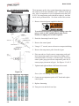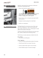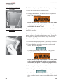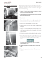
1
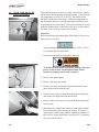
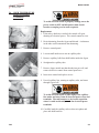
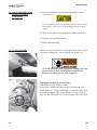
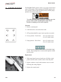
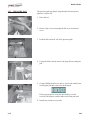
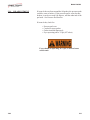
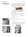
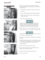
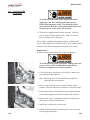
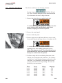
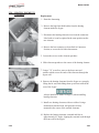
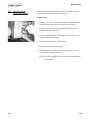
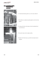
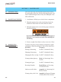
Model 590/592
SECTION 2.
MAINTENANCE
2-1.
INTRODUCTION
This section provides checkout and replacement procedures,
for various parts of the fryer. Before replacing any parts, refer
to the Troubleshooting Section to aid you in finding the cause
of the malfunction.
2-2.
MAINTENANCE HINTS
1. A multimeter will help you to check electric components.
2. When the manual refers to the circuit being closed, the
multimeter should read zero unless otherwise noted.
3. When the manual refers to circuit being open, multimeter
should read infinity.
Do not move fryer with hot shortening in the frypot or
filter pan. Severe burns can result from splashing hot
shortening.
4. Remove weights from frame to easily access rear of fryer.
2-3.
PREVENTIVE
MAINTENANCE
To ensure a long life of fryers and their components, regular
maintenance should be performed. Refer to the chart below.
Procedure
Frequency
Filtering of shortening
See KFC’s Standards Library
Changing of shortening
See KFC’s Standards Library
Changing the filter envelope See KFC’s Standards Library
Cleaning deadweight assy.
Daily-See Deadweight Valve
Section
Cleaning the frypot
See KFC’s Standards Library
Reversing lid gasket
Each 90 Days-see Reversing
Lid Gasket Section
Lubricate rear lid rollers
Annually-See Lubricating Lid
Rollers Section
Cleaning safety relief valve Annually-See Removal/Cleaning
of Safety Relief Valve Section
307
2-1
Model 590/592
2-4.
HIGH TEMPERATURE
LIMIT CONTROL
This high temperature control is a safety, manual reset control,
which senses the temperature of the shortening. If the shortening temperature exceeds 425°F (218°C), this switch opens
and shuts off the heat to the frypot. When the temperature of
the shortening drops to a safe operation limit, manually reset
by pressing the red reset button. The red reset button is located
under the control panel, in the front of the fryer, to the right of
the drain. Once reset, the frypot starts heating.
Checkout
Before replacing a high temperature limit control, check to see
that its circuit is closed.
The shortening temperature must be below 380°F (193°C)
to accurately perform this check.
1. Remove electrical power supplied to the fryer.
To avoid electrical shock or property damage, move the
power switch to OFF and disconnect main circuit
breaker, or unplug cord at wall receptacle.
2. Remove the control panel.
3. Remove the inner heat shield.
4. Remove two nuts securing the high limit bracket to unit,
and pull the bracket from the unit.
5. Remove two screws securing the high limit to the bracket,
and remove the high limit from the bracket.
6. Remove the two electrical wires from the high temperature
limit control.
7. Manually reset control, then check for continuity between
the two terminals after resetting the control. If circuit is
open, replace control, then continue with this procedure. (If
the circuit is closed, high limit is not defective. Reconnect
the two electrical wires.)
2-2
1103
Model 590/592
2-4.
HIGH TEMPERATURE
LIMIT CONTROL
(Continued)
To avoid electrical shock of property damage, move the
power switch to OFF and disconnect main circuit
breaker, or unplug cord at wall receptacle.
Replacement
1. If the tube is broken or cracked, the control will open,
shutting off electrical power. The control cannot be reset.
2. Drain shortening from the frypot and discard. A substance
in the tube could contaminate the shortening.
3. Remove control panel.
4. Loosen small inside screw nut on capillary tube.
5. Remove capillary bulb from bulb holder inside the frypot.
6. Straighten the capillary tube.
7. Remove larger outside nut that threads into pot wall, and
remove defective control from control panel area.
8. Insert new control and replace screws.
9. Uncoil capillary line, starting at capillary tube, and insert
through frypot wall.
To avoid electrical shock or other injury, run capillary
line under and away from all electrical power wires and
terminals. The tube must never be in such a position
where it could accidentally touch the electrical power
terminals.
10. Carefully bend the capillary tube as shown in photo and
place into bulb brackets.
1103
2-3
Model 590/592
2-4. HIGH TEMPERATURE
LIMIT CONTROL
(Continued)
11. Pull excess capillary line from pot and tighten nut into
frypot wall.
Be sure capillary bulb of high limit is positioned so it does
not interfere with carrier or get damaged when cleaning
frypot.
12. With excess capillary line pulled out, tighten smaller nut.
13. Replace inner and front panels.
14. Refill with shortening.
2-5. FUSE HOLDERS
There are two fuse holders on each model of the electric fryers.
To check or change fuse, unscrew black fuse holder cap.
To avoid electrical shock or property damage, move the
power switch to OFF and disconnect main circuit
breaker, or unplug cord at wall receptacle.
Checking Procedure for Fuse Holders
CONTROL PANEL FUSES 3 Phase
Remove the control panel and pull the wires from the fuse
holder terminals. Using a multimeter or continuity light, check
across the terminals. The circuit should be closed. If not, replace the fuse (HP# EF02-007) or fuse holder (HP# EF02-006).
2-4
1103
Model 590/592
2-6.
POWER/PUMP SWITCH
The POWER/PUMP switch is a three way rocker switch with a
center OFF position. With switch in the POWER position, the
fryer operates. With switch in PUMP position, the filter pump
operates, but the unit will not heat.
To avoid electrical shock or property damage, move the
power switch to OFF and disconnect main circuit
breaker, or unplug cord at wall receptacle.
Checkout
1. Remove control panel.
2. Label and remove wires from the switch.
3. OFF position-should be open circuit anywhere on switch.
4. Power position. Check from:
#5 to #6 closed circuit
#l to #2 closed circuit
5. Pump position. Check from:
#4 to #5 closed circuit
#3 to #2 closed circuit
Check across the jumpers on the wires of POWER/PUMP
switch. These jumpers have resistors and capacitors which
may be faulty.
Replacement
1. With control panel removed, and wires off of the switch,
push in on tabs on the switch to remove from the panel.
2. Replace with new switch, and reconnect wires to switch
following the wiring diagram.
3. Replace the control panel.
1103
2-5
Model 590/592
2-7. TEMPERATURE PROBE
REPLACEMENT
The temperature probe relays actual shortening temperature to
the control. If it becomes disabled, “E06” will show in the display. Also, if temperature is out of calibration more than 10°F,
or 10°C, the temperature probe should be replaced. An Ohm
check can be performed also. See chart at end of this section.
1. Remove electrical power supplied to the fryer.
To avoid electrical shock or property damage, move the
power switch to OFF and disconnect main circuit
breaker, or unplug cord at wall receptacle.
2. Drain the shortening from the frypot.
3. Remove the control panel.
4. Using a 1/2” wrench, remove the nut on compression fitting.
Figure 2-1
5. Remove the temperature probe from the frypot.
6. Place nut and new ferrule on new temperature probe and
insert temperature probe into compression fitting until it
extends one-half (1/2) inch (1.3 cm) into frypot. Use temperature probe gauge provided in temperature probe kit, to
ensure proper placement in frypot. See Figures 2-1 & 2-2.
7. Tighten hand tight and then a half turn with wrench.
Figure 2-2
Excess force will damage temperature probe.
8. Connect new temperature probe to PC board and replace
control panel.
9. Replace shortening.
10. Turn power on and check out fryer.
2-6
407
Model 590/592
2-8.
COMPLETE CONTROL
PANEL-HENNY PENNY
Should the control panel become inoperative, follow these
instructions for replacing the board.
1. Remove electrical power supplied to the fryer.
To avoid electrical shock or property damage, move the
power switch to OFF and disconnect main circuit
breaker, or unplug cord at wall receptacle.
2. Remove the two screws securing he control panel and lift
panel up and out
3. Unplug the connectors going to the control board.
4. Install a new control panel.
2-9.
PRESSURE REGULATION
The Henny Penny Fryer uses pressure as one of the components of the cooking process. Once the lid is sealed to the
frypot, and the solenoid valve closes, a deadweight valve maintains the correct pressure in the frypot.
The lid has minimal and limited maintenance and repair procedures, which are addressed in the following sections.
The following is a routine maintenance schedule for the Lid:
Every 90 days
• Clean and reverse the lid gasket
Yearly Inspection
• Check Lid Gasket for splits and tears-replace if necessary
1103
•
Check Pressure Pads for wear-rotate if necessary
•
Check Cam Slide Guides-replace if worn or broken
•
Check Lid Rollers-replace if cracked or damaged
2-7
Model 590/592
2-10. TILTING THE LID
UPRIGHT
The Lid Assembly is easily tilted up for cleaning or servicing.
1. Raise the lid and remove racks and carrier.
2. Grasping the lid handle, lift the front of the lid up until it
stops in an upright position.
Be sure the metal arm on the left side of the lid is in the
vertical position holding lid upright, or severe injuries
could result. (See photo at left).
2-11.
REVERSING THE LID
GASKET
The gray rubber gasket surrounding the inside of the lid is designed to be reversed.
Because of heat expansion and the pressure used for cooking
process, gasket is constantly under extreme stress. Reversing
the lid gasket will help to assure that the fryer will not lose
pressure through leakage.
1. Put the lid in the upright position, as previously described.
2. Using a thin blade screwdriver, pry out the gasket at the
corners. Remove the gasket.
Check the gasket for any tears or nicks. If the gasket is
damaged it needs to be replaced.
Be sure the metal arm on the left side of the lid is in the
vertical position holding lid upright, or severe injuries
could result. (See photo in Tilting Lid Upright section)
3. Clean the gasket and gasket seat with hot water.
4. Rotate the gasket with the opposite side facing out.
Install the 4 corners of the lid gasket. Smooth gasket into
place, working from the corners towards the middle of each
side.
2-8
1103
Model 590/592
2-12.
LID COUNTERWEIGHT
CABLES
The Lid Counterweight in the back of the fryer balances the
weight of the lid system to allow easier opening and closing of
the lid. The weight has two cables attached to it, and weighs
about 150 lbs. (67.5 Kg).
1. Using a 3/8” socket, remove the nuts securing rear shroud
of the fryer and remove the shroud.
2. Using Phillips-head screwdriver, remove screws securing
the top cap and remove cap.
3. Raise the lid.
4. Unscrew broken cable from the weight assembly and the
bracket attached to the fryer, and remove broken cable.
5. Screw a 5/16” nut on each end of the new cable.
6. Using a wrench, screw new cable into the weight assembly
until tight.
7. Using a 1/2” wrench, tighten nut (already threaded on the
cable) against weight assembly, securing the cable into the
weight assembly.
8. Pull cable over pulley and down behind weight assembly.
9. Insert cable into the hole in the bracket and screw a 5/16”
nut onto end of cable. Tighten cable, by screwing the cable
through this nut until the weight assembly becomes
level.
The safety cable should now have slack in it with the
weight assembly level.
10. Tighten nut against the top of the bracket, securing the
cable.
11. Replace the top cap and rear shroud. The repair is now
complete.
1103
2-9
Model 590/592
2-13.
PRESSURE PAD
The pressure pads are plastic strips that the lid cam presses
against to seal the lid.
1. Raise the lid.
2. Remove the 4 screws securing the lid cover and remove
cover.
3. Push the lid cam back, off of the pressure pads.
4. Using an Allen wrench, remove the large bolt securing the
pad.
5. Using a Phillips head screw driver, remove the small screw
securing the pad and remove the broken pad.
If the pressure pad is worn, but not broken, it can be
reversed 180 degrees, and the other end of the pad used.
6. Install new pad in reverse order.
2-10
1103
Model 590/592
2-14.
LID ADJUSTMENT
If steam leaks out from around the lid gasket, the pressure pads
could be worn or broken. If the pressure pad is worn, but not
broken, it can be reversed 180 degrees, and the other end of the
pad used. See Pressure Pad Section.
If steam leaks, check for:
•
•
•
•
Pressure pad wear
Cracked or worn gasket
Gasket installed improperly
Fryer operating above 12 psi (827 mbar)
Fryer should be operating at 12 psi, or serious burns
could result.
1103
2-11
Model 590/592
2-15.
SOLENOID VALVE
This is an electro-mechanical device that causes pressure to be
held in the frypot. The solenoid valve closes at the beginning
of the Cook Cycle and opens automatically at the end of the
Cook Cycle. If this valve should become dirty, or the Teflon
seat nicked, pressure will not build up. The electric fryer uses a
208/240 volt 60 hertz coil (50 hertz internationally).
To avoid electrical shock or property damage, move the
power switch to OFF and disconnect main circuit
breaker, or unplug cord at wall receptacle.
Coil Check Procedure
Remove the solenoid wires from the wire nuts which are found
behind the control panel. Check across wires.
RESULTS
208/240 Volt, 60 Hertz
150 Ohms
208/240 Volt, 50 Hertz
230 Ohms
Replacement
1. Remove the right side panel.
2. Remove the “tru-arc” retaining clip on top of coil housing.
3. Remove the cover.
4. If only the coil is to be replaced, disconnect two coil wires
at wire nuts in the coil housing. Remove coil, insert new
coil, and connect wires at wire nuts. Assemble in reverse
order of disassembly.
The wires may be connected in any order.
2-12
1103
Model 590/592
2-15.
SOLENOID VALVE
(Continued)
5. If the core-disc assembly is sticking due to buildup of
shortening, breading, and food particles, proceed with the
following steps:
a. Unscrew the solenoid bonnet assembly from solenoid
valve body.
b. Remove solenoid bonnet assembly and bonnet gasket.
c. Remove the core-disc assembly, core spring retainer,
and the core spring.
d. Wash all these parts in hot water.
If Teflon seals need to be replaced, proceed to Step 6;
otherwise, assemble in reverse order of disassembly.
Assemble valve core and blade with smooth side and
rounded edge of blade toward the disc spring guide.
6. Repair kit, Part No. 17120, is available if any of the seals
must be replaced. If one seal is defective, replace all seals.
Solenoid body must be removed from the fryer for replace
ment of seals. Continue on to step 7.
7. Loosen wires on the strain relief and pull the wires through
the relief.
8. With the bonnet assembly and core-disc assembly removed,
disconnect the two nut fittings. One connects the solenoid
valve to the deadweight, the other is attached to the
condensation tank.
9. Remove the elbows from the solenoid valve.
10. Remove the two adapter screws which attach the pipe
adapter to the solenoid valve body.
11. Remove the disc spring, guide, and Teflon seat.
12. Clean the valve body.
1103
2-13
Model 590/592
2-15.
SOLENOID VALVE
(Continued)
13. Wet “O” ring around seat with water and insert O-ring
assembly (flat side first) in valve through “IN” side of
body. Use an eraser end of pencil and press in the Teflon
seal until it snaps into place. Be careful not to mar or nick
the seat.
The smallest nick can cause a pressure leak. Replace all
O-ring seals that are in the parts kit and reassemble the
valve.
14. If the complete valve is to be replaced, follow steps 1, 2, 3,
4, 5, 7, 8 and 9 in this section.
2-16.
DEADWEIGHT VALVE
DO NOT ATTEMPT TO REMOVE DEADWEIGHT
CAP WHIILE FRYER IS OPERATING. SEVERE
BURNS OR OTHER INJURIES WILL RESULT.
The operating valves are located behind the lid. The valve, left of
the pressure gauge, is a 14 1/2 lb. (999 mbar) safety relief valve,
and the one on the right is the deadweight valve.
Deadweight valve
2-14
Valves are working properly, when the pointer on the gauge is
in the “OPERATING ZONE” (green area). The gauge pointer
should not normally exceed the operating zone. If the pressure
builds to 14 1/2 lbs.(999 mbar), the safety relief valve will open
to release steam pressure from inside frypot.
1103
Model 590/592
2-16.
DEADWEIGHT VALVE
(Continued)
DO NOT PULL THE RING ON THE SAFETY
RELIEF VALVE. HOT STEAM WILL BE
RELEASED AND SEVERE BURNS WILL RESULT.
ORIFICE
CAP
DEADWEIGHT
1. At the end of each day’s usage of the fryer, the deadweight
valve must be cleaned. The fryer must be OFF and pressure
released. Open the lid and then remove the deadweight
valve cap and deadweight.
Failure to clean the deadweight assembly daily could
result in the fryer building too much pressure. Severe
injuries and burns could result.
2. Wipe both the cap and weight with a soft cloth. Make
certain to thoroughly clean inside cap, the weight seat, and
around deadweight orifice.
3. Dry the parts and replace immediately to prevent damage
or loss.
2-17.
REMOVAL & CLEANING
OF SAFETY RELIEF
VALVE
The safety relief valve should be cleaned once a year.
SAFETY RELIEF VALVE
DO NOT ATTEMPT TO REMOVE SAFETY VALVE
WHILE FRYER IS OPERATING, OR SEVERE
BURNS OR OTHER INJURIES WILL RESULT.
1. Remove pressure gauge.
1103
2-15
Model 590/592
2-17.
REMOVAL & CLEANING
OF SAFETY RELIEF
VALVE (Continued)
2. Use a wrench to loosen the valve from the pipe tee, turn
counterclockwise to remove.
3. Clean the inside of the pipe tee with hot water.
Turn the safety relief valve towards the rear of the fryer
when reinstalling safety relief valve.
4. Immerse the safety relief valve in a soapy water solution
for 24 hours. Use a 1 to 1 dilution rate. The valve cannot
be disassembled. It is factory preset to open at 14 1/2
pounds of pressure. If it does not open or close, it must
be replaced.
DO NOT DISASSEMBLE OR MODIFY THIS VALVE.
TAMPERING WITH THIS VALVE COULD CAUSE
SERIOUS INJURIES AND WILL VOID AGENCY
APPROVALS AND APPLIANCE WARRANTY.
2-18.
PRESSURE GAUGE
Calibration Steps
The pressure gauge can be recalibrated should it be out of
adjustment.
1. Remove the rim and glass.
2. If the indication hand shows a pressure or vacuum reading
when it should stand at “0”, turn the recalibrator screw
in the same direction in which the indicating hand is to
be moved until the hand stands a proper “0” position.
3. Replace the rim and glass.
Adjusting
Screw
Cleaning Steps
1. Remove the gauge and check inside the pipe fittings from
deadweight body. Make certain fittings are clean and open.
2. Clean and reinstall the gauge.
2-16
1103
Model 590/592
2-19. CONTACTORS
The electric fryer requires two switching contactors: a primary
and a heat contactor. The primary contactor energizes (contacts
close) any time the POWER/PUMP switch is in the POWER
position, and the temperature of the shortening is below 420° F
( 215° C). The high limit cuts power at the primary contactor
if the temperature of the shortening is above 420° F ( 215° C).
The primary contactor supplies power to one side of the heat
contactor.
Primary
The heat contactor is controlled by the computer controller.
When the controller calls for heat, the heat contactor applies
power to one side of the heating elements. When the heat contactor and primary contactor are energized (contacts closed) the
electric heating elements heat the shortening.
The photo shows a mercury heat contactor, but CE countries will have an electromechanical heat contactor.
Heat
30
31
32
Checkout
1. Remove electrical power supplied to the fryer.
To avoid electrical shock or property damage, move the
power switch to OFF and disconnect main circuit
breaker, or unplug cord at wall receptacle.
2. Remove the control panel.
34
1103
35
36
3. Label and remove wires from contactors and perform a
check on both contactors as follows:
Test Points
Results
From 23 to 29
open circuit
From 24 to 28
open circuit
From 25 to 27
open circuit
From 30 to 34
open circuit
From 31 to 35
open circuit
From 32 to 36
open circuit
From 33 to 37
ohm reading 1700
From 22 to 26
ohm reading 415
2-17
Model 590/592
2-19. CONTACTORS
(Continued)
To avoid electrical shock, make connections before
applying power, take reading, and remove power
before removing meter leads. The following checks
are performed with the wall circuit breaker closed and
the main power switch in the ON position.
4. With power reapplied and in a heat-up mode, check the
power going to both contactor coils. This is to be sure
power is going to the contactors.
If no voltage is found going into the primary contactor coil,
check wiring, high limit, and drain switch. If no voltage at heat
contactor coil, check wiring and connections at PC board.
Replacement
If either contactor proves defective, replace as follows:
To avoid electrical shock or property damage, move the
power switch to OFF and disconnect main circuit
breaker, or unplug cord at wall receptacle.
1. Label and remove only those wires directly connected to
the contactor being replaced.
Hint: Removing the left side panel may be helpful in
replacing the heat contactor.
2. Remove the mounting screws on the base plate of the
primary contactor and remove contactor. Proceed to step 5.
3. Remove the screws securing the mercury contactor bracket
to the mounting plate and remove bracket and contactor.
4. Remove the screws securing the contactor to the bracket
and remove contactor from bracket.
5. Install new contactor in reverse order.
6. Install control panel and reconnect power to the fryer and
test for proper operation.
2-18
1103
Model 590/592
2-20.
HEATING ELEMENTS
The electric model fryer uses 2 heating elements.
Heating elements are available in 208, 220/240, 380 and
415 volts. Check the data plate, on the shroud behind the
lid, to determine the correct voltage elements.
1. Remove the electrical power supplied to the unit.
To avoid electrical shock or property damage, move the
power switch to OFF and disconnect main circuit
breaker, or unplug cord at wall receptacle.
2. Remove the control panel.
3. Remove both side panels.
4. Remove upper screws and loosen the lower screws, to the
front control shroud, and hinge it down. (See photo at left)
To avoid electrical shock, make connections before
applying power, take reading, and remove power
before removing meter leads. The following checks are
performed with the wall circuit breaker closed and the
main power switch in the ON position.
5. Perform an amp check on one heating element at a time
with the wires connected to the contactors. The 2 heaters
actually have 3 small heating elements on the inside of the
outer plate. It is important to check between the correct
wires to obtain the accurate amp reading. The wires are
labeled for your convenience.
Wires
L1-L3
L3-L2
L2-L1
L1-L2
L3-L2
L2-L1
1103
Power
8500W
8500W
8500W
8500W
8500W
8500W
Voltage
208V
208V
208V
240V
240V
240V
Amperage
47.8
47.9
48.0
39.4
40.1
39.9
2-19
Model 590/592
2-20.
HEATING ELEMENTS
(Continued)
Replacement
1. Drain the shortening.
2. Remove the high limit bulb holder from the heating
element inside the frypot.
3. Disconnect the heating element wires from the contactors.
Label each so it can be replaced in the same position on the
new element.
4. Remove the heat contactor, as described in Contactors
Section, to access the left side element nuts.
5. Loosen the screws on the element spreaders.
6. Slide element spreaders to the center of the heating element.
7. Using a 7/8” crowsfoot, remove the brass nuts and
washers which secure the ends of the elements through the
frypot wall.
8. Remove the heating elements from the frypot as a group by
lifting the far end, and sliding them up and out towards the
rear of the frypot.
Always install new rubber O-rings (2) when installing
heating elements.
9. Install new heating elements with new rubber O-rings
mounted on terminal ends, and spreaders loosely
mounted in the center of the stacked elements.
10. Replace the heating elements, terminal end first at
approximately 45º angle, slipping the terminal ends through
the front wall of the frypot.
2-20
1103
Model 590/592
2-20.
HEATING ELEMENTS
(Continued)
10. Replace the brass nuts and washers on the heating element
terminals. Tighten the brass nuts to 30 foot lbs of torque.
11. Replace heat contactor.
12. Move the element spreaders from the center of the ele
ment, into a position which will spread each element apart
evenly on all four sides, and tighten.
13. Replace the high limit bulb holder on the top element, and
position the bulb between the top and second element midway from side to side, and tighten screw which holds the
bulb in place.
14. Reconnect the wires to the appropriate terminal as labeled
when they were removed.
15. Replace the front control shroud and control panel.
16. Replace side panels.
17. Connect the power cord to the wall receptacle or close
wall circuit breaker.
Heating elements should never be energized without
shortening in the frypot, or damage to elements could
result.
1103
2-21
Model 590/592
2-21.
DRAIN MICROSWITCH
Upon pulling out on the drain handle, the microswitch should
be activated and the unit will not heat, but when the handle is
pushed back, the unit should operate properly. The bracket on
the microswitch is slotted so it can be adjusted backward or
forward.
1. Remove electrical power supplied to the unit.
To avoid electrical shock or property damage, move the
power switch to OFF and disconnect main circuit
breaker, or unplug cord at wall receptacle.
2. The following check should be made to determine if the
drain switch is defective.
a. Remove bracket from the unit.
b. Remove wires from the switch.
c. Check for continuity across the two outside terminals
on the drain switch. If circuit is open, the Drain Switch
is bad. The circuit should only be opened by pressing
on the actuator of the Drain Switch.
1/8” (4 mm) Gap
3. To replace switch, remove switch from the bracket, and
install switch in reverse order.
4. Test to see if drain valve handle actuates the switch. The
gap between the drain switch and the shaft should be no
more than 1/8” (3 mm).
HINT: Listen for audible click of switch while pulling drain
valve handle.
2-22
1103
Model 590/592
2-22.
DRAIN VALVE
AND EXTENSION
The drain valve opens when the drain valve handle is pulled
out and drains the shortening out of the pot.
Replacement
1. Using a 3/8” socket, remove the nuts securing the drain
switch bracket, and pull the bracket from the studs.
2. Remove the nut securing the drain handle and pull the
handle from the drain valve.
3. Using a large adjustable wrench, unscrew the drain valve
and extension from the unit.
4. Replace the drain valve and extension.
5. Replace the drain switch bracket.
6. Adjust the microswitch to be no more than 1/8” (3 mm)
from the shaft of the drain valve.
HINT: Listen for audible click of switch while pulling drain
valve handle.
1103
2-23
Model 590/592
2-23.
NYLATRON STRIPS
REPLACEMENT
1. Raise the lid and remove the retention ring from one end of
the lid pin.
2. Slide the lid pin from unit.
3. Lift the lid from unit.
The lid weighs 80 lbs (36 kg). Take care when lifting lid
to prevent personal injury.
4. Using a 3/8” socket, remove the nuts securing the rear
shroud and remove shroud.
5. Using a Phillip’s-head screwdriver, remove the screws
securing the top cap and remove top cap.
6. Remove the bolts securing the nylatron strips to the weight
assembly and remove strips from weight assembly.
7. Using a Phillip’s-head screwdriver, remove the screws
securing the front shroud.
8. Unfasten the exhaust hose from the hose clamp.
2-24
1103
Model 590/592
2-23.
NYLATRON STRIPS
REPLACEMENT
(Continued
9. Lift the front shroud up and out, over the arm of the lid.
10. Thread the new nylatron strip through the track in the front
shroud.
11. Lining up the holes in the strips, fit the front shroud back
over the lid arms.
12. Secure the strips to the weight assembly.
13. Replace back shroud, top cap, and lid, and replacement is
complete.
1103
2-25