1
Freescale Semiconductor
Application Note
Document Number: AN3761
Rev. 0, 11/2008
Using Freescale Devices for
Contactless Touch Applications
Touch Pad Demonstrator Board
by: Luděk Šlosarčík
Rožnov Czech System Center
Czech Republic
The touch pad demonstrator board is a development
board for the demonstration of two Freescale devices: the
proximity capacitive sensor MPR084, and the USB
microcontroller MC9S08JM60.
The basic component of this board is a proximity
capacitive touch sensor controller, the MPR084. This is
an inter-integrated circuit communication (I2C) driven
capacitive touch sensor controller, optimized to manage
an 8-element touch pad capacitive array.
The second important component of this board is the
8-bit MC9S08JM60 MCU with a full-speed USB
module.
This application also offers a demonstration of
FreeMASTER visualization software on the PC, which
can co-operate with the demo board, read data from it,
and render this data in visual format on the PC.
© Freescale Semiconductor, Inc., 2008. All rights reserved.
Contents
1
Application Description . . . . . . . . . . . . . . . . . . . . . . . . . . 2
1.1 Features . . . . . . . . . . . . . . . . . . . . . . . . . . . . . . . . . 3
2
Basic Features. . . . . . . . . . . . . . . . . . . . . . . . . . . . . . . . . 3
2.1 MPR084 Proximity Capacitive Touch Sensor
Controller . . . . . . . . . . . . . . . . . . . . . . . . . . . . . . . . . 3
2.2 MC9S08JM60 Microcontroller . . . . . . . . . . . . . . . . . 5
2.2.1 MC9S08JM60 USB Module Description. . . . . . . 6
3
Hardware Description . . . . . . . . . . . . . . . . . . . . . . . . . . . 8
4
Software Description . . . . . . . . . . . . . . . . . . . . . . . . . . . 11
4.1 MC9S08JM60 Firmware . . . . . . . . . . . . . . . . . . . . 11
4.1.1 FreeMASTER Driver. . . . . . . . . . . . . . . . . . . . . 13
4.1.2 CMX-USB Communication Driver . . . . . . . . . . 15
4.1.3 I2C Communication Driver . . . . . . . . . . . . . . . . 15
4.1.4 Main Program Loop . . . . . . . . . . . . . . . . . . . . . 16
4.2 FreeMASTER Visualization Script. . . . . . . . . . . . . 17
4.2.1 Driver Installation . . . . . . . . . . . . . . . . . . . . . . . 17
4.2.2 Test the Demo Board by Running FreeMASTER
Visualization Script . . . . . . . . . . . . . . . . . . . . . . 19
Appendix A References . . . . . . . . . . . . . . . . . . . . . . . . . . . . . 21
Appendix B Touch Pad Demo Board PCB . . . . . . . . . . . . . . 22
Application Description
1
Application Description
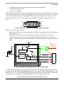
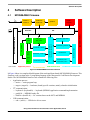
A block diagram of the touch pad demo application is shown in Figure 1. The full touch pad demo
application consists of: touch pad demo board, optional external ITO screen (electrodes) and
FreeMASTER visualization script on a PC. The goal of the touch pad demo board design is to provide a
small portable board with the capability of demonstrating the Freescale capacitive touch sensor controller
and its connection to a PC via a Freescale USB device. The touch pad demo board incorporates an internal
8-element touch pad on the top of the PCB. There are two main components on the back side of the touch
pad demo board, connected via the I2C serial interface on the board:
• The MPR084 capacitive touch sensor controller, which registers any touches on the internal pads
or the external ITO screen. This ITO screen may be connected to the demo board through a ZIF
connector parallel to the internal pads, so there are two independent methods for touching which
may be used simultaneously.
• The MC9S08JM60, an 8-bit MCU device with a full-speed USB 2.0 controller on the chip. This
device reads any touches which are recognized by the MPR084 and turns on the relevant LED on
the board. It may also send touch information to the FreeMASTER visualization script via USB,
but only if there is an application running on the PC.
Figure 1. Block Diagram of Touch Pad Demo Application
Using Freescale Devices for Contactless Touch Applications, Rev. 0
2
Freescale Semiconductor
Basic Features
The touch pad demo board is powered from the PC via the USB power line, so this board must be
connected to the PC via a USB cable even if no FreeMASTER visualization script is running on the PC.
1.1
Features
The main features of the touch pad demonstrator include:
•
•
•
•
•
•
•
2
A board that is optimized to manage an 8-element touch pad
Two versions of contactless electrodes, either of which may be accessible:
— Onboard E-field electrodes
— An external ITO module, connected to the board through a ZIF connector
Connection of the board to a PC through USB, using the virtual serial COM port on the PC side —
communication device class (CDC)
Touch visualization via:
— Built-in LEDs on the demo board
— FreeMASTER visualization script on the PC
Basic settings of the demo board via FreeMASTER visualization script on the PC:
— Press type (mode):
– Non-buffered mode — several pads can be read at the same time
– Buffered mode — only a single pad can be read at one time
— Touch delay in buffered mode — 0.25 s to 2.5 s
— Maximum touches allowed in non-buffered mode — 1 to 7 pads
— Type of buffer — touch, release, or touch and release
Power to the touch pad demo board from the USB power line
All components are on the back of the PCB — the keypad side is perfectly flat for easy mounting
Basic Features
In this section the basic features of the two main components of the touch pad demo board are described.
There are also other components on the back side of the demo board for its proper operation including
capacitors, resistors, inductors, connectors, LEDs, voltage regulator, and crystal.
2.1
MPR084 Proximity Capacitive Touch Sensor Controller
The MPR084 is an inter-integrated circuit communication (I2C) driven capacitive touch sensor controller,
optimized to manage an 8-element touch pad capacitive array. The device can accommodate a wide range
of implementations through three output mechanisms, and has many configurable options.
The MPR084 uses an I2C interface to communicate with the host that configures the operation, and an
interrupt to inform the host of status changes. The MPR084 includes a piezo sound driver which provides
audible feedback to simulate mechanical key clicks. The MPR08x family has several implementations to
use in your design, including control panels and switch replacements. The MPR084 controls individual
Using Freescale Devices for Contactless Touch Applications, Rev. 0
Freescale Semiconductor
3
Basic Features
touch pads. Other members of the MPR08x family are well suited for other application interface situations,
such as individual touch pads or rotary/touch pad combinations.
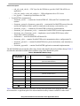
The MPR084 consists of primary functional blocks which are shown in Figure 2: interrupt controller, I2C
serial interface, sound controller, configuration and status registers, touch pad decoder, magnitude
comparator and recalibrator, EMI burst/noise rejection filter, capacitance measurement analog front end.
SDA
SCL
ATTN
I2C
Serial
Interface
AD0
Speaker
Speaker
Driver
Controller
Pad
Enabled
Current
Pad
Touch
Pad
Identify
Decoder
8
8
8
Capacitance Measurement A.f.e.
Clear
Set
Rate
EMI Burst/Noise Reject Filter
Interrupt
Controller
Configuration And Status Register
IRQ
Magnitude Comparator and Recalibrator
Masks
8
8
Touch
Pads
Figure 2. Functional Block Diagram of MPR084
Features:
• 1.8 V to 3.6 V operation
• 41 μA average supply current
• 2 μA low standby current
• Variable low-power mode response time (32 ms – 4 s)
• Rejection of unwanted multi-key detections from EMI events, such as PA bursts or user handling
• Ongoing pad analysis and detection not reset by EMI events
• FIFO data buffering for shortest access time
• IRQ output indicates when FIFO has data
• System can set interrupt behavior as immediate after an event, or program a minimum time
between successive interrupts
• Current touched pad position is always available on demand for polling-based systems
• Speaker output can be enabled to generate key-click sound when pad is touched
• Two hardware selectable I2C addresses allow two devices on a single I2C bus
• Configurable real-time auto calibration
• 5 mm × 5 mm × 1 mm 16-lead QFN package
• –40 °C to +85 °C operating temperature range
Using Freescale Devices for Contactless Touch Applications, Rev. 0
4
Freescale Semiconductor
Basic Features
Implementations:
• Control panels
• Switch replacements
• Touch pads
Typical applications:
• Appliances
• PC peripherals
• Access controls
• MP3 players
• Remote controls
• Mobile phones
2.2
MC9S08JM60 Microcontroller
MC9S08JM60 series MCUs are members of the low-cost, high-performance HCS08 family of 8-bit
microcontroller units (MCUs). All MCUs in the family use the enhanced HCS08 core and are available
with a variety of modules, memory sizes, memory types, and package types.
The 8-bit MC9S08JM60 MCUs are devices with a full-speed USB module, providing best-in-class USB
module performance, system integration, and software support.
Features:
• 8-bit HCS08 central processor unit (CPU):
•
— 48 MHz HCS08 CPU (central processor unit)
— 24 MHz internal bus frequency
— HC08 instruction set with added BGND instruction
— Background debugging system
— Breakpoint capability to allow single breakpoint setting during in-circuit debugging
— In-circuit emulator (ICE) debug module
— Support for up to 32 interrupt/reset sources
Memory options:
•
— Up to 60 KB of on-chip in-circuit programmable flash memory with block protection and
security options
— Up to 4 KB of on-chip RAM
— 256 bytes of USB RAM
Clock source options:
— Crystal, resonator, and external clock
— MCG (multi-purpose clock generator) - PLL and FLL; internal reference clock with trim
adjustment
Using Freescale Devices for Contactless Touch Applications, Rev. 0
Freescale Semiconductor
5
Basic Features
•
•
—
Peripherals:
— USB — USB 2.0 full-speed (12 Mbps) device controller
— ADC — 12-channel, 12-bit analog-to-digital converter
— SCI — Two serial communication interfaces
— SPI — Two 8-bit or 16-bit selectable serial peripheral interface modules
— IIC — Inter-integrated circuit bus module to operate at up to 100 kbps
— Timers — One 2-channel and one 6-channel 16-bit timer/pulse-width modulator
— KBI — 8-pin keyboard interrupt module
— RTC — Real-time counter with binary-based or decimal-based prescaler
Input/output:
— Up to 51 general-purpose input/output pins
— Software selectable pullups on ports when used as inputs
— Software selectable slew rate control on ports when used as outputs
— Software selectable drive strength on ports when used as outputs
— Master reset pin and power-on reset (POR)
— Internal pullup on RESET, IRQ, and BKGD/MS
Typical applications:
• Game pads
• Security control panels
• Printers
• PC peripherals
2.2.1
MC9S08JM60 USB Module Description
USB is a host-controlled serial bus which uses a star topology. All communication is initiated by the host
— all devices are polled. In any USB system there is only one host. USB devices are hubs or functions.
Hubs provide additional attachment points to the USB host. Functions provide capabilities to the system,
such as an ISDN connection, a digital joystick, or speakers.
Features:
• USB 2.0 compliant — 12 Mbps full-speed data rate
• Seven USB endpoints
— Bidirectional endpoint 0
— Six unidirectional data endpoints configurable as interrupt, bulk, or isochronous
— Endpoints 5 and 6 support double-buffering
• 256 bytes USB RAM
• USB reset options — internal MCU reset generated, BUS reset generated
• Converts USB differential voltages to digital logic signal levels
Using Freescale Devices for Contactless Touch Applications, Rev. 0
6
Freescale Semiconductor
Basic Features
•
•
•
Operations can be suspended and resumed with remote wakeup support
On-chip USB pullup resistor
On-chip 3.3 V regulator
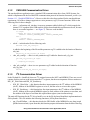
USB transfers signals and power over a four-wire cable with twisted pairs as specified in the Universal
Serial Bus Specification Rev. 2.0. Data is signaled differentially over two wires, D+ and D–. A non-return
to zero invert encoding scheme is used together with a sync field to synchronize the host and receiver
clocks. The other two wires (5 V power lines VBus and GND) are assigned to supply devices — see
Figure 3.
VBus
D+
D–
GND
VBus
D+
D–
GND
Figure 3. USB Lines —Data (D+, D–) and Power Supply (VBus, GND)
USB devices have two power modes:
• Bus-powered: USB devices are powered from the USB bus. The maximum current drawn from the
host is 500 mA.
• Self-powered: USB devices use an individual power supply to provide the current for all
components, so that its power consumption is limited by the capability of the external power
supply. A USB device whose current consumption is more than 500 mA must adopt self-powered
mode.
.
VDD (2.7–5.5 V)
1) VBus –
Bus-Powered
USBVREN
(3.9–5.5 V)
XTAL
2) External Power –
Self-Powered
VUSB (3–3.6 V)
Rs
External
Pullup
3.3 V Regulator
External Power
(Regulator)
USBPU
Rf
Internal
Pullup
USB RAM
and
Control Logic
EXTAL
Optional
External Regulator Bead
USBDP
XCVR
USB Module
VDD or
VSS
VBus
D+
2xRs
USBDN
D–
Vss
Optional
MC9S08JM60
MCU
Bead
GND
USB
Connector
Figure 4. USB Connection Example (Bus-Powered / Self-Powered)
A USB host uses the pullup resistor to detect the connection of the USB device and identifies the device
speed (low, full, high). Full-speed and high-speed devices are terminated with the pullup resistor (1.5 kΩ)
on the D+ line to 3.3 V. The MC9S08JM60 USB module supports only the full-speed (FS) USB data rate.
It can choose to use an internal or external pullup resistor on the D+ line (see Figure 4).
Using Freescale Devices for Contactless Touch Applications, Rev. 0
Freescale Semiconductor
7
Hardware Description
3
Hardware Description
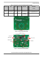
All of the components necessary for proper operation are on a small board, 80 × 60 mm, except for the
optional external ITO screen. Please note that the required 3.3 V power supply voltage is generated from
the USB interface using a small analog regulator (U3).
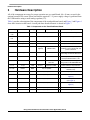
Table 1 provides a description of the components of the touch pad demo board, and Figure 5 and Figure 6
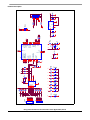
show their location on the board. A touch pad demo board schematic is shown in Figure 7.
Table 1. Components on the Touch Pad Demo Board
Reference(s)
Value
Package Manufacturer
C1, C4, C6,
C10
10 μF / 10 V
Case A
C2, C3, C5,
C11
0.1 μF
C7
Order Code
Qt
Description
Any acceptable
4
Tantalum polarized filter capacitors
0805
Any acceptable
4
Ceramic filter capacitors
0.47 μF
0805
Any acceptable
1
Ceramic filter capacitor
C8, C9
22 pF
0805
Any acceptable
2 Filter capacitors for crystal connection
D1 .... D10
HSMA-C265
SMD
Avago
(Agilent)
HSMA-C265
(HSMG-C265)
10
Red (Green) LEDs for optical
feedback on the touched pads and
power control line
JP1
CON10_ZIF
1.0 mm
Molex
52271-1079
1
ZIF/FFC 1.0 mm interface for
connecting an external ITO screen
J1
CON USB
Mini-B
Molex
54819-0572
1
USB receptacle for connecting the
touch pad demo board to a PC
J2
HDR 2X3
2.54 mm
Samtec
TSM-103-01-SDV-P-TR
1
SMT terminal strip for background
debug mode on MC9S08JM60 MCU
L1, L2
1.8 μH
1206
Bourns
CS321613-1R8K
2
Ferrite multi-layer chip inductors
R1...R8
750 kΩ
0805
Any acceptable
8
Pullup resistors for capacitive
electrode array
R10...R15
4.7 kΩ
0805
Any acceptable
6
General pullup resistors
R16, R17
33 Ω
0805
Any acceptable
2 Resistors Rs for USB connection (see
Figure 4)
R19
0Ω
0805
Any acceptable
1
R18
1 MΩ
0805
Any acceptable
1 Resistor Rf for crystal connection (see
Figure 4)
R20
470 Ω
0805
Any acceptable
1
Attenuator for power LED
R21...R29
220 Ω
0805
Any acceptable
9
Attenuators for user LEDs
Resistor Rs for crystal connection
(see Figure 4)
Using Freescale Devices for Contactless Touch Applications, Rev. 0
8
Freescale Semiconductor
Hardware Description
Table 1. Components on the Touch Pad Demo Board (continued)
Reference(s)
Value
Package Manufacturer
Order Code
Qt
Description
U1
MPR084
TSSOP-16
Freescale
MPR084EJ
1
Proximity capacitive touch sensor
controller
U2
MC9S08JM60
LQFP-44
Freescale
U3
NCP561SN33
SOT23-5
ON Semi
NCP561SN33T1G
1
Low-dropout voltage linear regulator
to supply demo board
X1
12 MHz
SMD-49
Daishinku
SMD-49
12.000 MHz
tolerance ±50 ppm
1
Crystal resonator for MCU
MC9S08JM60CLDE 1
8-bit MCU with USB module
PADs
Figure 5. Touch Pad Demo Board (Top)
MC9S08JM60
BDM Connector
Crystal
Power LED
USB Socket
ZIF Connector
LDO Regulator
MPR084
LEDs
LEDs
Figure 6. Touch Pad Demo Board (Bottom)
Using Freescale Devices for Contactless Touch Applications, Rev. 0
Freescale Semiconductor
9
Touch
JP2
JP1
1
2
3
4
5
6
7
8
10
9
8
7
6
5
4
3
2
1
R20
TL
N
TR
E
BR
S
BL
W
TR
E
GND
BR
S
BL
W
TL
N
D2
R21
220R
680K
R8
680K
R7
680K
R6
680K
R5
680K
R4
680K
R3
680K
D3
R22
220R
16
15
14
13
12
11
10
9
E1
E2
E3
E4
E5
E6
E7
E8
D4
R23
220R
GND
D5
R24
220R
7
8
5
6
1
2
C1
10UF
MPR084EJ
AD0
SOUNDER
SCL
SDA
ATTN
IRQ
U1
+
3.3V
GND
3.3V
D6
R25
220R
GND
/ATTN
/IRQ
C2
0.1uF
D7
R26
220R
D8
R27
220R
SCL
SDA
3.3V
R14
R13
R12
R10
R11
3.3V
D9
R28
220R
GND
C3
0.1uF
29
30
33
2
3
36
/ATTN
/IRQ
/RESET
BKGD
R15
40
41
42
43
1
44
23
24
25
26
27
28
SCL
SDA
LED_W
LED_BL
LED_TL
LED_N
LED_S
3.3V
GND
+
3.3V
C6
10UF
GND
MC9S08JM60CLDE
IRQ/TPMCLK
RESET
BKGD/MS
PTD0/ADP8/ACMP+
PTD1/ADP9/ACMPPTD2/KBIP2/ACMPO
PTC0/SCL
PTC1/SDA
PTC2
PTC3/TxD2
PTC4
PTC5/RxD2
PTB0/MISO2/ADP0
PTB1/MOSI2/ADP1
PTB2/SPSCK2/ADP2
PTB3/SS2/ADP3
PTB4/KBIP4/ADP4
PTB5/KBIP5/ADP5
U2
3.3V
C7
0.47uF
GND
GND
1
C8
22pF
X1
R18
2
20
18
19
21
22
34
35
37
38
4
5
6
7
8
9
10
11
12
13
14
15
3.3V
XTAL
EXTAL
LED_E
LED_BR
LED_TR
R19
0 OHM
C9
22pF
GND
12MHZ
1M
VUSB33
USBDN
USBDP
PTG0/KBIP0
PTG1/KBIP1
PTG2/KBIP6
PTG3/KBIP7
PTG4/XTAL
PTG5/EXTAL
PTF0/TPM1CH2
PTF1/TPM1CH3
PTF4/TPM2CH0
PTF5/TPM2CH1
PTE0/TxD1
PTE1/RxD1
PTE2/TPM1CH0
PTE3/TPM1CH1
PTE4/MISO1
PTE5/MOSI1
PTE6/SPSCK1
PTE7/SS1
EXTAL
GND
D1
470R
TL
TR
BR
N
E
5.0V
2
CON10_ZIF
HSMA-C265
LED_N
3
VDD
S
HSMA-C265
1
2
4
W
HSMA-C265
LED_E
1
2
LED_S
1
2
LED_W
VSS
HSMA-C265
1
2
LED_BR
R2
680K
HSMA-C265
4k7
BL
HSMA-C265
4k7
HSMA-C265
1
2
4k7
LED_TL
1
2
LED_TR
1
2
4k7
HSMA-C265
LED_BL
1
4k7
31
16
VDDAD/VREFH
VDD1
VSSAD/VREFL
VSS1
VSSOSC
32
17
39
+
D+
D-
GND
3.3V
R17 33 R
R16 33 R
C4
10UF
GND
GND
/RESET
2
4
6
C5
0.1uF
5
VOUT
1
L2
1.8UH
VIN
2
GND
5
GND
0.1uF
1
GND
4
3
C11
J1
1
2
2
D+
L1
1.8UH
D-
1
NCP561SN33T1G
GND
5.0V
J2
HDR_2X3
3.3V
U3
1
3
5
BKGD
4k7
HSMA-C265
XTAL
2
3.3V
S3
S1
CONN MINIUSB_TYPE_AB 5
+
C10
10UF
5.0V
GND
G
1
NC
4
ID
ENABLE
D+
3
D-
GND
5V
2
10
S4
S2
R1
Hardware Description
Figure 7. Touch Pad Demo Board Schematic
Using Freescale Devices for Contactless Touch Applications, Rev. 0
Freescale Semiconductor
Software Description
4
Software Description
4.1
MC9S08JM60 Firmware
I2C
Line
keyboard.c
keyboard.h
hardi2c.c
hardi2c.h
USB
target.c
target.h
ppr081.h
Real Time
API
Color codes:
freemaster_rec.h
Application process
I2C communication
freemaster_private.h
freemaster.h
freemaster_cfg.h
freemaster_scope.c
freemaster_appcmd.c
freemaster_protocol.c
cdct_usb_config.c
cdct_usb_config.h
freemaster_serial.c
application (main.c)
usb_cdc.c
usb_cdc.h
freemaster_protocol.h
usb.c
usb.h
hcc_types.h
MC9S08JM60 USB Module
Line
freemaster_tsa.c
freemaster_tsa.h
USB communication
FreeMASTER communication
Figure 8. MC9S08JM60 Firmware Overview
In Figure 8 there is a complete block diagram of the touch pad demo board (MC9S08JM60) firmware. This
firmware code is written in the C programing language in the Metrowerks CodeWarrior Development
Studio. The MC9S08JM60 firmware code contains the following files:
• Application process:
— main.c — main program loop
— target.c (target.h) — hardware (board) specific routines; mainly related to initialization
• I2C communication:
— keyboard.c (keyboard.h) — keyboard (MPR084) application command implementation
— ppr081.h — MPR084 header file
— hardi2c.c (hardi2c.h) — I2C routines between the MCU and MPR084
• USB communication:
— usb.c. (usb.h) — USB device driver source
Using Freescale Devices for Contactless Touch Applications, Rev. 0
Freescale Semiconductor
11
Software Description
•
— usb_cdc.c (usb_cdc.h) — CDC layer for the USB driver; provides UART like API for an
application
— cdct_usb_config.c (cdct_usb_config.h) — USB configuration for a CDC device
— hcc_types.h — common type definitions for USB
FreeMASTER communication:
— freemaster_serial.c — contains the FreeMASTER SCI, USB, and JTAG communication
routines
— freemaster_protocol.c (freemaster_protocol.h) — contains the FreeMASTER protocol decoder
and also the handlers of basic protocol commands (read memory, write memory, etc.)
— freemaster_scope.c — contains the FreeMASTER oscilloscope implementation
— freemaster_rec.c (freemaster_rec.h) — contains the FreeMASTER recorder implementation
— freemaster_tsa.c (freemaster_tsa.h) — implements a new FreeMASTER feature called
Target-Side Address translation
— freemaster.h — main FreeMASTER API header file
— freemaster_cfg.h — contains FreeMASTER serial communication driver configuration file
— freemaster_private.h — contains FreeMASTER driver private declarations, used internally by
the driver
— freemaster_appcmd.h — contains FreeMASTER application commands implementation
The MC9S08JM60 microcontroller offers many features that simplify the touch pad demo design. Table 2
describes the individual available blocks and their usage in the introduced system.
Table 2. MC9S08JM60 Module Usage
Module Available on
MC9S08JM60
Used
Purpose
USB
yes
Communication between the touch pad demo board and PC
(external communications)
ACMP
no
ADC
no
SCI
no
SPI
no
I2C
yes
Communication between the MCU and MPR084
(internal communications)
TPM1
yes
Touch delay in buffered mode
TPM2
no
KBI
no
RTC
no
IRQ
yes
Information about new data in the FIFO of the MPR084
Table 3 shows how much memory is needed to run the touch pad demo board using the MC9S08JM60
microcontroller. A significant part of the microcontroller memory remains available for other tasks.
Using Freescale Devices for Contactless Touch Applications, Rev. 0
12
Freescale Semiconductor
Software Description
Table 3. Memory Usage
4.1.1
Memory
Available
(MC9S08JM60)
Used
Flash
60912 Bytes
8358 Bytes
RAM
4096 Bytes
641 Bytes
FreeMASTER Driver
The MC9S08JM60 application uses the standard FreeMASTER serial communication driver version 1.1.0
Beta. Because there is no USB support in this driver, some program changes to it were necessary. Refer to
these files for the changes:
• freemaster_private.h — there is one conditional compilation statement added on line 246:
#ifndef FMSTR_USE_USB
#define FMSTR_USE_USB 0
#endif
•
freemaster_protocol.c — there is one conditional compilation statement added in function
FMSTR_Init:
#if FMSTR_USE_SCI || FMSTR_USE_JTAG || FMSTR_USE_USB
/* initialize communication and start listening for commands */
FMSTR_InitSerial();
#endif
•
freemaster_HC08.c — SCI interrupt handlers (for receive and transmit) are compiled conditionally
on type of communication (in this case, on USB):
#if !FMSTR_USE_USB
.
.
#endif
•
freemaster_HC08.h — there is a defined USB configuration macro on line 165:
#ifndef FMSTR_USE_USB
#define FMSTR_USE_USB 1
#define FMSTR_SCI_HAS_TXQUEUE 0
#endif
and an adjusted SCI configuration macro:
#ifndef FMSTR_USE_SCI
#define FMSTR_USE_SCI 0
#endif
•
freemaster_serial.c — there are some USB configuration statements added at the beginning of the
file and two USB functions defined:
#if FMSTR_USE_USB
#include "usb.h"
/* USB driver from CMX */
#include "usb_cdc.h"
/* CDC-device driver from CMX */
#define FMSTR_USB_PUTCHAR(ch) (void) cdc_putch(ch)
#define FMSTR_USB_GETCHAR() cdc_getch()
#define USBREG3V 0
/* disable internal 3.3V regulator on chip */
#endif
Next, there is added initialization of the CDC device in the function called FMSTR_InitSerial:
#if FMSTR_USE_USB
/* initialize USB driver with internal 3.3V On-chip regulator On/Off */
Using Freescale Devices for Contactless Touch Applications, Rev. 0
Freescale Semiconductor
13
Software Description
usb_cfg_init(USBREG3V);
/* initialize CDC device */
cdc_init();
#endif
In function FMSTR_SendResponse, there is one conditional compilation statement added with a
new USB function for transferring “start of message” (SOB):
#if FMSTR_USE_USB
FMSTR_USB_PUTCHAR(FMSTR_SOB);
#elif FMSTR_USE_SCI
.
.
In function FMSTR_Tx there is one conditional compilation statement added with a new USB
function for transferring one character (ch):
#if FMSTR_USE_USB
FMSTR_USB_PUTCHAR((FMSTR_U8) ch);
#elif FMSTR_USE_SCI
.
.
Next, there is a whole new function added called FMSTR_ProcessUSB:
#if FMSTR_USE_USB
void FMSTR_ProcessUSB(void)
{
/* transmitter active and empty? */
if (pcm_wFlags.flg.bTxActive)
{
FMSTR_Tx();
/* read-out and ignore any received character (loopback) */
if(cdc_kbhit())
{
FMSTR_BCHR nRxChar = 0U;
nRxChar = (FMSTR_BCHR) FMSTR_USB_GETCHAR();
}
}
/* transmitter not active, able to receive */
else
{
/* data byte received? */
if (cdc_kbhit())
{
FMSTR_BCHR nRxChar = 0U;
nRxChar = (FMSTR_BCHR) FMSTR_USB_GETCHAR();
FMSTR_Rx(nRxChar);
}
}
}
#endif
and this new function is used in FMSTR_Pool together with code for CDC processing:
#if FMSTR_USE_USB
/* polled USB mode */
FMSTR_ProcessUSB();
/* CDC device implementation */
cdc_process();
#else
.
.
Using Freescale Devices for Contactless Touch Applications, Rev. 0
14
Freescale Semiconductor
Software Description
4.1.2
CMX-USB Communication Driver
The touch pad demo application uses a standard USB communication driver from CMX Systems, Inc.,
which is implemented in the FreeMASTER communication protocol in function freemaster_serial.c (see
Section 4.1.1, “FreeMASTER Driver”). However, this driver has been updated for the touch pad demo
requirement. All of these changes appertain to a new parameter, reg3V, in some functions. Refer to the
following files for these changes:
• usb.c — in function usb_init there is one new parameter added called reg3V which controls the
internal 3.3V regulator in the USB module (for the demo board this regulator must be off, because
there is an external regulator — see Figure 7). This new code includes:
if (reg3V)
/* Enable phy
USBCTL0 =
else {
/* Enable
USBCTL0 =
}
•
and 3.3V voltage regulator. */
USBCTL0_USBPHYEN_MASK | USBCTL0_USBVREN_MASK;
phy */
USBCTL0_USBPHYEN_MASK;
usb.h — in this header file the following code:
#include "cdct_usb_config.h"
is added to the beginning of the file and the parameter reg3V is added to the declaration of function
usb_init:
extern hcc_u8 usb_init(hcc_u8 reg3V);
•
cdct_usb_config.c — there is a new parameter reg3V added to function usb_cfg_init:
void usb_cfg_init(hcc_u8 reg3V)
{
(void)usb_init(reg3V);
}
•
cdct_usb_config.h — there is a new parameter reg3V added to the declaration of function
usb_cfg_init:
extern void usb_cfg_init(hcc_u8 reg3V);
4.1.3
I2C Communication Driver
In the file hardi2c.c (hardi2c.h) there are I2C routines between the MCU and MPR084. There are several
routines for direct access to the microcontroller I2C registers, but the most important of these routines are
HW_IIC_WriteValue and HW_IIC_ReadArray.
• HW_IIC_WriteValue — this function has three input parameters: the I2C address of the MPR084
(0x4C), address of the MPR084 register to write to, and the value to write to this register.
• HW_IIC_ReadArray — this function has four input parameters: the I2C address of the MPR084
(0x4C), address of the required MPR084 register to read, address of the pointer to store data, and
the number of the byte to read from this required data register (auto-increment loop).
The main API functions for the I2C driver hardi2c.c are in the file keyboard.h and their implementation in
file keyboard.c. This file includes the following functions (API keyboard interface):
• ppr_CheckFifoData — this function checks the FIFO buffer of the MPR084 for new data (touch
pad has been touched). Apart from this, this function prepares information from the More Data flag
Using Freescale Devices for Contactless Touch Applications, Rev. 0
Freescale Semiconductor
15
Software Description
•
•
4.1.4
of the FIFO register into variable next_data. This information shows whether or not data will
remain in the buffer after the current data is read. This function is called by the main program after
the interrupt comes. Function ppr_CheckFifoData doesn’t have an input parameter, only an output
parameter. It returns one byte of information about the touched pad. For one of the 8 touch pads
this function returns a number from 0 to 7 (only one pad at a time = single press mode). If there is
no touched pad, this function returns 0xFF. The main program uses this function only in buffered
(single press) mode.
ppr_ReadStatusReg — this function reads directly the STATUS register of the MPR084 for new
data (touched pad), but unlike function ppr_CheckFifoData does not read the FIFO buffer.
Therefore, function ppr_ReadStatusReg must be called continuously in the main loop — otherwise
any touched pads may be lost. This function does not have an input parameter, only an output
parameter. Function ppr_ReadStatusReg returns one word of information about the touched pad.
For one of eight touch pads this function returns a number from 0 to 255 (several pads at a time =
multiple press mode). If there is no touched pad, this function returns 0. The main program uses
this function only in non-buffered (multiple press) mode.
ppr_init — this function initializes the majority of the MPR084 registers. These registers include:
Configuration register, Fault register, Touch Pad Configuration register, Touch Acquisition Sample
Rate register, Master Tick Counter register, Electrode Channel Enable registers, and Sensitivity
Threshold registers. Function ppr_init has two input parameters: intr, which disables or enables the
interrupt pin in the Configuration register, depending on the mode; and buffer, which selects
various types of buffer in the Touch Pad Configuration register. This function also clears the FIFO
buffer of the MPR084. This function has no output parameter. It is called from the main program
during the initialization sequence and also after the press type (mode) or the buffer type has been
changed.
Main Program Loop
The main program loop is realized in file main.c. At the beginning of this file there is initialization which
includes these parts: hardware of the MCU & watchdog, FreeMASTER & CMX-USB drivers, I2C
(MPR084) driver and Timer 1 settings. In the main program loop these actions are periodically realized:
• MPR084 reinitialization depending on the change of mode or the type of buffer from
FreeMASTER
• Watchdog reset
— Read data from MPR084 depending on mode:
— Read periodically the touched pads from the STATUS register of the MPR084 in non-buffered
mode, and check if the current number of touched pads is lower than the content of the
maxTouchMultiply register
— Read one touchpad pad directly from the FIFO of the MPR084 after an interrupt has been
received or variable next_data from the previous cycle has been set (in buffered mode only). If
there is a touched pad, it also starts Timer1 for measurement of the touch delay.
• LED control
• FreeMASTER processing with the built-in USB communication — FMSTR_Pool
Using Freescale Devices for Contactless Touch Applications, Rev. 0
16
Freescale Semiconductor
Software Description
Apart from these periodic actions, there can occur two independent interrupts in real time: one from
Timer1 for termination of a touched pad indication (but only in buffered mode), and the second from the
USB communication module for sending or receiving a data packet.
4.2
FreeMASTER Visualization Script
FreeMASTER visualization script is the software for remote visualization and remote re-setting of the
touch pad demo board. This software runs on a PC which connects to the demo board via a USB cable.
FreeMASTER visualization script is the application which runs under FreeMASTER software (formerly
known as PC Master software). FreeMASTER software is one of the off-chip drivers which supports
communication between the target microcontroller and a PC. This tool allows the programmer to remotely
control an application using a user-friendly graphical environment running on a PC. It also provides the
ability to view some real-time application variables in both text and graphic form. FreeMASTER software
runs under Windows 98, 2000, or XP. It is a versatile tool to be used for multipurpose algorithms and
applications. It provides a lot of excellent features, including:
• Real-time debug tool
• Diagnostic/visualization tool
• Demonstration tool
• Education tool
4.2.1
Driver Installation
You must install several programs and drivers from the CD or website before or during the first connection
of the demo board to your computer. This installation includes the following steps:
• Install the latest version of Adobe Flash Player onto your PC for proper working of the
FreeMASTER visualization script. Adobe Flash Player is available at
http://www.macromedia.com/go/getflashplayer.
• Insert the provided CD in your computer. In the Windows start menu double-click on the
fmaster13-8.exe program on your CD.
• Follow the onscreen instructions in the FreeMASTER InstallShield Wizard until installation is
complete.
• Connect the demo board to your PC USB slot via the provided USB cable (the power LED on the
upper right side of the demo board will light at this time).
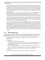
• The ‘Found New Hardware’ announcement should appear on the Windows Toolbar.
• Then the installation wizard starts searching for new hardware. Choose “Install from a list or
special location” (see Figure 9).
Using Freescale Devices for Contactless Touch Applications, Rev. 0
Freescale Semiconductor
17
Software Description
Figure 9. Found New Hardware Wizard Dialogue
•
•
•
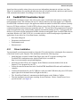
Point to the Installation CD as the driver path CDC-DRV on your CD, click on the Next button,
and installation should continue (see Figure 10).
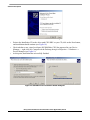
Check whether a new virtual serial port (HC9S08JMxx CDC) has appeared in your Device
Manager — right-click My Computer on the Desktop, then go to Properties --> Hardware -->
Device Manager (see Figure 11).
At this point, installation has successfully finished.
Figure 10. USB-CDC Driver Installation Wizard Dialogues
Using Freescale Devices for Contactless Touch Applications, Rev. 0
18
Freescale Semiconductor
Software Description
Figure 11. New CDC in Device Manager
4.2.2
Test the Demo Board by Running FreeMASTER Visualization Script
Now that you have successfully completed the software setup, test your demo board by running the
FreeMASTER visualization script. You must copy the file called TPDemo_Visualization.exe from the
installation CD to your local hard drive and then double-click on this file. Follow the onscreen instructions
in the InstallShield Wizard until installation is complete. Then double-click on the TouchPadDemo.pmp
program in the directory TPDemo_Visualization. Following this, a visualization script will appear on your
PC (see Figure 12).
Figure 12. FreeMASTER Visualization Script
Now you must set the proper virtual serial communication port in menu Project/Options (see Figure 13).
This is the same port used as during driver installation — in this case, COM5. Others settings, such as the
communication speed, don’t matter in this case (they would apply only to a CDC device).
Then you must click on the red Start/Stop Communication button (third icon on the upper left side in the
program). If all previous installations and settings are correctly done, the FreeMASTER visualization
Using Freescale Devices for Contactless Touch Applications, Rev. 0
Freescale Semiconductor
19
Software Description
script for the touch pad demo is now running. So, if you press the pad(s) on the demo board, the green
LED(s) on the demo board and appropriate graphical pad(s) in the program turn on. You may also see
appropriate text values of the touched pad(s) in the Watch Properties window in the program (near the
STATUS parameter on the bottom edge of the window).
Figure 13. Communication Port Setting
You may also set several parameters of the demo board by clicking on the value in the Watch Properties
window. These parameters include:
• Press type (mode) is a basic setting on the demo board to determine the type of pressure that has
been applied to the MPR084. The demo board has two primary methods for reporting data:
— Multiple press (non-buffered mode) — this mode allows several pads to be pressed at the same
time. In the firmware code there is a cyclic reading of the STATUS register of the MPR084,
even if no pads are pressed. This is an instantaneous output.
— Single press (buffered mode) — in this mode, the application program reads touched pads on
the MPR084 directly from the FIFO buffer of the MPR084, but only if there is an interrupt from
it. The MPR084 has one interrupt output that is configured by registers and alerts the
application when a touch or fault is detected. If there is an interrupt, this signifies that there is
new data available in the FIFO buffer. The interrupt is de-asserted on the first read of the FIFO
register and cannot be reasserted for buffer data until the FIFO is empty (a FIFO buffer read
will clear the IRQ pin of the MPR084).
• Touch delay in buffered mode — this option is active only in buffered mode and represents the time
for storage of one touched pad. The resolution of this parameter is 250 ms. It ranges from 0 s to 2.5
s, so there are 10 choices in the menu.
• Maximum touches allowed in non-buffered mode — adjusts the maximum number of keys that can
be concurrently reported as touched, but only in non-buffered mode. There is a range of 1–7 keys
for this option. When this option is set to any number in this range, all touches greater than this
number will be ignored and unreported.
• Type of buffer — this option configures the type of buffer in buffered mode:
— No touch and no release buffer — this is only an information option (settings are not active) in
the case of non-buffered mode.
Using Freescale Devices for Contactless Touch Applications, Rev. 0
20
Freescale Semiconductor
References
— Touch buffer — this option determines whether or not data is logged in the FIFO any time a
button is pressed.
— Release buffer — this option determines whether or not data is logged in the FIFO when the
touch pad transitions from a touched to an untouched state.
— Touch and release buffer — this option combines both of the previous types of buffer.
Appendix A References
•
•
•
•
•
•
•
•
MC9S08JM60 Data Sheet, Freescale Semiconductor, Rev. 2, 3/2008
MPR084 Data Sheet, Freescale Semiconductor, Rev. 4, 10/2008
NCP561 Data Sheet, ON Semiconductor, Rev. 5, 8/2007
FreeMASTER for Embedded Application, User Manual, Rev. 0.1, 6/2004
AN2471, “PC Master Software Communication Protocol Specification”
AN3492,” USB and Using the CMX USB Stack”
AN3564, “Customize the USB application Using the MC9S08JM”
AN3565, “USB and Using the CMX USB Stack with 9S08JM Devices”
Using Freescale Devices for Contactless Touch Applications, Rev. 0
Freescale Semiconductor
21
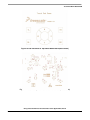
Touch Pad Demo Board PCB
Appendix B Touch Pad Demo Board PCB
Figure 14. Top Layer of Demo Board (Not to Scale)
Figure 15. Bottom Layer of Demo Board (Not to Scale)
Using Freescale Devices for Contactless Touch Applications, Rev. 0
22
Freescale Semiconductor
Touch Pad Demo Board PCB
Figure 16. Pad Placement on Top Side of Demo Board (Not to Scale)
Figure 17. Bottom Component Placement on Demo Board (Not to Scale)
Using Freescale Devices for Contactless Touch Applications, Rev. 0
Freescale Semiconductor
23
How to Reach Us:
Home Page:
www.freescale.com
Web Support:
http://www.freescale.com/support
USA/Europe or Locations Not Listed:
Freescale Semiconductor, Inc.
Technical Information Center, EL516
2100 East Elliot Road
Tempe, Arizona 85284
+1-800-521-6274 or +1-480-768-2130
www.freescale.com/support
Europe, Middle East, and Africa:
Freescale Halbleiter Deutschland GmbH
Technical Information Center
Schatzbogen 7
81829 Muenchen, Germany
+44 1296 380 456 (English)
+46 8 52200080 (English)
+49 89 92103 559 (German)
+33 1 69 35 48 48 (French)
www.freescale.com/support
Japan:
Freescale Semiconductor Japan Ltd.
Headquarters
ARCO Tower 15F
1-8-1, Shimo-Meguro, Meguro-ku,
Tokyo 153-0064
Japan
0120 191014 or +81 3 5437 9125
[email protected]
Asia/Pacific:
Freescale Semiconductor Hong Kong Ltd.
Technical Information Center
2 Dai King Street
Tai Po Industrial Estate
Tai Po, N.T., Hong Kong
+800 2666 8080
[email protected]
For Literature Requests Only:
Freescale Semiconductor Literature Distribution Center
P.O. Box 5405
Denver, Colorado 80217
1-800-441-2447 or 303-675-2140
Fax: 303-675-2150
[email protected]
Document Number: AN3761
Rev. 0
11/2008
Information in this document is provided solely to enable system and software
implementers to use Freescale Semiconductor products. There are no express or
implied copyright licenses granted hereunder to design or fabricate any integrated
circuits or integrated circuits based on the information in this document.
Freescale Semiconductor reserves the right to make changes without further notice to
any products herein. Freescale Semiconductor makes no warranty, representation or
guarantee regarding the suitability of its products for any particular purpose, nor does
Freescale Semiconductor assume any liability arising out of the application or use of any
product or circuit, and specifically disclaims any and all liability, including without
limitation consequential or incidental damages. “Typical” parameters that may be
provided in Freescale Semiconductor data sheets and/or specifications can and do vary
in different applications and actual performance may vary over time. All operating
parameters, including “Typicals”, must be validated for each customer application by
customer’s technical experts. Freescale Semiconductor does not convey any license
under its patent rights nor the rights of others. Freescale Semiconductor products are
not designed, intended, or authorized for use as components in systems intended for
surgical implant into the body, or other applications intended to support or sustain life,
or for any other application in which the failure of the Freescale Semiconductor product
could create a situation where personal injury or death may occur. Should Buyer
purchase or use Freescale Semiconductor products for any such unintended or
unauthorized application, Buyer shall indemnify and hold Freescale Semiconductor and
its officers, employees, subsidiaries, affiliates, and distributors harmless against all
claims, costs, damages, and expenses, and reasonable attorney fees arising out of,
directly or indirectly, any claim of personal injury or death associated with such
unintended or unauthorized use, even if such claim alleges that Freescale
Semiconductor was negligent regarding the design or manufacture of the part.
RoHS-compliant and/or Pb-free versions of Freescale products have the functionality
and electrical characteristics as their non-RoHS-compliant and/or non-Pb-free
counterparts. For further information, see http://www.freescale.com or contact your
Freescale sales representative.
For information on Freescale’s Environmental Products program, go to
http://www.freescale.com/epp.
Freescale™ and the Freescale logo are trademarks of Freescale Semiconductor, Inc.
All other product or service names are the property of their respective owners.
© Freescale Semiconductor, Inc. 2008. All rights reserved.