1
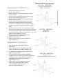
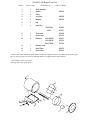
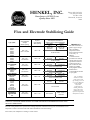
Henkel, Inc.
P.O. Box 1322
Hammond, LA
70404
(985) 345-2171
www.keenovens.com
Henkel, Inc.
P.O. Box 1322 * Hammond, Louisiana * 70404 * (985) 345-2171
www.keenovens.com
Models K-450 Bench Type
Installation Instructions & Repair Parts List
One Year Limited Warranty
Henkel, Inc. warrants its products against defects in material and workmanship. Henkel,
Inc. will either repair or replace without charge any properly installed product which fails
under normal operating conditions within one year from date of installation, provided it is
returned to our factory, transportation prepaid, and our inspection determined it to be
defective under the terms of this warranty. The warranty covers only equipment
manufactured by Henkel, Inc., and does not extend to transportation, installation, or
replacement charges at the buyers’ facility; nor does it apply to any other equipment of
another manufacturer used in conjunctions with Henkel, Inc. equipment. No other
warranty, expressed or implies exists beyond that included in this statement.
Recommended Spare Parts
When it is critical to have continuous operation of this unit,
we suggest having the following spare parts on hand:
Heating Element
Power Cord
Thermostat
K-450 Accessories List
Stack Kit: allows for stacking or piggybacking of two (2) K-450 ovens
Thermometer Kit
General Information
The K-450 oven with its superior structural design and energy efficient heat exchange will
provide many years of durable, trouble free service.
Keen Ovens
K-450 SPECIFICATIO N S
Electrode Capacity
450lbs. 18" rods
Volts
120 V
240 V
480 V
W atts
1000W
1000W
1000W
Therm ostat
Dial Adjustable
Tem perature
150ºF-550ºF
Insulation
2"
Interior Dim ensions
19.5"D X 20"
Net W eight
81lbs.
Shipping W eight
86lbs.
Shipping Dim ensions
26" X 28" X 26"
Safety Precautions
Read all instructions completely before attempting to operate this unit.
*** SAVE THESE SAFETY INSTRUCTIONS ***
To reduce the risk of electrical shock, fire, or personal injury follow the guidelines below:
•
Before connecting unit to a power source, be sure the voltage supplied is the same as that
specified on the nameplate of the unit.
•
Check outlet to ensure proper grounding of the electrical cable. Have a licensed electrician
check the A/C power outlet if you are not sure.
•
Use this unit for its intended purpose as described by literature.
•
Make sure power cord is located so that it will not be stepped on, tripped over, or otherwise
subjected to stress of heat, oil, or sharp edges. Do not close doors on the cord.
•
To reduce the risk of damage to the electric plug and cord, disconnect by plug rather than by
the cord.
•
Do not use this unit if cord or plug is in poor condition. If it has been exposed to weather or
immersed in water, have a qualified serviceman inspect and replace parts as necessary.
•
WARNING! NEVER HANDLE PLUG, CORD, OR UNIT WITH WET HANDS OR
WHILE STANDING IN WATER.
•
Use special care when moving heavily loaded units.
•
Do not store combustible material on or around the unit.
•
Do not operate this unit empty.
•
When using the unit at a distance where an extension cord becomes necessary, a 3-conductor
grounding cord of adequate size must be used for safety, and to prevent loss of power and
overheating. Use only a UL listed extension cord suitable for outdoor use. Make certain wire
size is large enough for A/C amperage rating of unit.
Operation
Load oven with desired amount of electrodes. To turn on the unit, simply plug the power
cord into appropriate single phase A/C source and adjust thermostat to desired setting. (Check
nameplate for voltage.) The 120V units are supplied with a three conductor 8” power cord. The
240V and 480V units are supplied with an 8’ UL listed 16/3 SJ power cord (plug not provided).
All units meet electrical code requirements when used with a grounding plug and a grounded
receptical.
*** CAUTION!! DO NOT USE ON D/C POWER SUPPLY! ***
Temperature Setting
The thermostat is adjustable from 150ºF (37.8ºC) to 550ºF (287.8ºC). Turn thermostat
knob to desired temperature by aligning with red line on chrome bezel. Pilot light indicates when
power is supplied to the heating element. The thermostat is accurate to ±23ºF (14ºC) at the
sensor. Temperature variance is minimal throughout the oven due to the heat exchanging
qualities of the Keen shelving system.
** CAUTION!! Surface temperature of heating element will exceed 500ºF.
Electrodes adversely affected by high heat should be stored on upper shelves of oven. **
Guide to Storage
See the enclosed guide to storage. This guide may be used in the absence of storage
information from the electrode manufacturer. In critical situations, contact your electrode
manufacturer.
Functional Description
These models are designed for the small to medium shop. They allow storing at optimum
temperature, protecting electrodes from harmful moisture. These ovens are compact and energy
efficient, therefore an economical buy. All bench types are thermostatically controlled. The shelf
design accommodates 50lb. electrode containers eliminating the need to remove the rods from
the container. Loose electrodes may also be stored in shelf compartments.
Scheduled Maintenance
The manufacturer recommends that the unit be unloaded and cleaned of debris and dust
every six months. It is recommended that a temperature probe be placed inside the unit and the
thermostat calibration checked at this time.
Venting
Your model K-450 oven is vented through a screened plug at the rear of the oven.
Troubleshooting
The Keen oven model K-450 requires a minimal amount
of electrical knowledge to repair if necessary.
IF OVEN FAILS TO OPERATE – NO HEAT
1. Check power source.
2. Check power cord continuity. Replace cord assembly if faulty.
3. If pilot light glows, voltage is being supplied to he heating element. Check element
continuity. If defective, replace.
4. If thermostat cannot be heard clicking on and off when dial is rotated, and if pilot light fails
to operate, replace thermostat
IF OVEN OVERHEATS
1. If oven fails to cycle on and off and reaches a temperature above 550ºF, thermostat is faulty
and needs replacing.
2. If oven operates but is off from setting see calibration instructions.
Corrective Maintenance
CHANGING THE HEATING ELEMENT
1.
2.
3.
4.
5.
6.
Disconnect power source and remove any rods from oven.
Remove element cover.
Remove element mounting nuts and top ceramic insulators.
Remove nine (9) mounting screws from leg assembly and lift oven clear of leg.
Remove wire connectors from element leads.
Remove old element from oven by lifting element over mounting bolts and pulling element
leads through conduit. Remove bottom ceramic insulators.
7. Install new male ceramic insulators, element, female insulators and hex nuts.
8. Insert element leads through conduit and reconnect with original electrical leads.
9. Replace front leg assembly being sure wiring is not crimped between leg and oven wall.
Model K-450 Wiring Diagrams
120 Volts / 1000 Watts
CHANGING THE THERMOSTAT
1. Disconnect from the power source.
2. Remove rods from oven.
3. Remove element cover and pull temperature-sensing
tube from holder.
4. Loosen setscrew in thermostat knob and remove knob.
Remove chrome mounting ring (bezel).
5. Remove nine (9) mounting screws from leg assembly
and lift oven clear of leg
6. Remove electrical leads from thermostat and remove
thermostat by pulling sensing tube through conduit.
7. To replace new thermostat, pass sensing tube through
conduit, being sure there is adequate length to reach the
holder.
8. Reconnect electrical leads to new thermostat and mount
thermostat to chrome ring (bezel) loosely with red indicting
line in upward position. Place knob on thermostat stem and
check rotation of knob. When knob turns freely, remove and
tighten chrome mounting ring (bezel)
9. Replace leg assembly being sure wiring is not
crimped between oven wall and leg.
10. Replace thermostat knob.
11. Insert temperature-sensing tube into holder and
replace element cover.
15 AMP/ 125-Volt Grounding Plug
NEMA 5-15P Provided
240 Volts / 1000 Watts
Grounding Plug
NEMA 5-15P
THERMOSTAT CALIBRATION
1. Turn on unit. Set control dial at desired
temperature.
2. Allow control to cycle at least three times and
observe temperature at middle of fourth cycle.
3. If calibration is required, carefully remove dial
knob. Do not turn shaft.
4. Turn calibration screw in center of dial shaft.
(Turning set screw clockwise decreases temperature.
Turning setscrew counter-clockwise increases
temperature. One-fourth [1/4] turn equals
approximately 35ºF.)
5. Allow unit to cycle at least three times and
observe temperature at middle of fourth
cycle. Readjust calibration screw if
necessary. Replace dial knob
480 Volts / 1000 Watts
20 AMP/ 480-Volt
Grounding Plug NEMA 8-20P Not Provided
Model K-450 Repair Parts List
ITEM #
QUAN./UNIT
DESCRIPTION
PART NUMBER
1
2
3
1
1
1
Shelf Assembly
Handle
Collar
430102
4
1
Vent Plug
490108
5
1
Magnets
490103
6
1
Leg
7
1
Neon Pilot
120V/240V
301085
480V
301101
8
1
Thermostat
301038
9
10
1
1
Power Cord
240V1000W
Elements
301155
301027
301125
301129
11
1
120V1000W
480V/1000W
Element Cover
12
13
1
1
Name Plate
Strain Relief
450103
301043
** Please state model number and serial number and specify voltage and wattage when ordering repair parts, spare
parts, or accessory parts. All necessary attaching hardware is supplied with each part ordered.
(Item numbers refer to pictorial
drawings below for repair parts.)
HENKEL, INC.
Manufacturer of KEEN Ovens
Quality Since 1923.
Phone (985) 345-2171
Fax (985) 345-5653
PO Box 1322
Hammond, Louisiana
70401
Flux and Electrode Stabilizing Guide
Type (AWS)
Air Conditioned
Storage
Before Opening
Dry Rod
Oven Holding
After Opening
Standard
EXX10
EXX11
EXX12
EXX13
EXX20
EXX30
Iron Powder
EXX14
EXX24
EXX27
Iron PowderLow Hydrogen
EXX18
EXX28
Low Hydrogen
EXX15
EXX16
Low-Hydrogen
High Tensile
EXXX15
EXXX16
180°F ± 25°
two hours
80°F ± 20°
60% ± 10% RH
140°F ± 30°
90°F ± 20°
50% RH max
140°F ± 30°
90°F ± 20°
50% RH max
400°F ± 50°
90°F ± 20°
50% RH max
400°F ± 50°
90°F ± 20°
50% RH max
Granulated or
Agglomerated
180°F ± 25°
two hours
325°F ± 25°
one hour
Three hour total
180°F ± 25°
two hours
700°F ± 100°
one-half hour
Two & one-half hour total
180°F ± 25°
two hours
600°F ± 100°
one-half hour
Two & one-half hour total
400°F ± 50°
180°F ± 25°
two hours
700°F ± 100°
one-half hour
Two & one-half hour total
180°F ± 25°
one hour
90°F ± 20°
50% RH max
240°F ± 25°
one hour
Three hour total
Stainless
Inconel
Monel
Nickel
Brasses
Bronzes
Hard Surfacing
Special Alloys
After Exposure to Moisture a
Sufficient Time to affect Weld Quality
Recondition
Rebake
Step 1
Step 2
350°F ± 50°
one hour
225°F ± 50°
Two hour total
90°F ± 20°
50% RH max
240° F ± 50°
Flux
Not required
700°F ± 100° ∅
two hours
CONTACT YOUR ELECTRODE MANUFACTURER FOR SPECIFIC INFORMATION INVOLVING
CRITICAL OPERATIONS.
Electrode coating should not be exposed to the rebaking temperature without first having been reconditioned at a lower
temperature. Failure to observe this rule will result in breakdown of electrode coatings.
After rebake, lower temperature to holding level until reissue.
IMPORTANT:
This table is offered as a
guide to proper storage
and oven holding
temperatures for the
most common electrodes
in use today. In
addition,
recondition/rebake
procedures for electrode
coatings that have been
exposed to moisture for
a sufficient period of
time to affect the weld
quality are included.
Good judgment and the
manufacturer’s
recommendations should
be your guide.
Note: In the HTS
Stainless electrode
groups, and 15 & 16
type coatings, there can
be a greater difference
in the maximum
temperature
requirements for
rebaking than those
shown. This can be
handled by special
request to the particular
manufacturer involved.