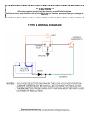
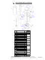
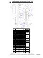
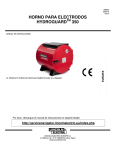
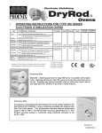
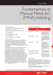
1
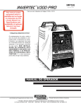
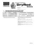
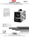
Electrode Stabilizing
DryRod
d II
®
Ovens
I.
OPERATING INSTRUCTIONS FOR TYPE 2 SERIES PORTABLE
ELECTRODE STABILIZATION OVENS
Part Number
Description - (All 50-60 cycles)
Temperature Range
1205510
120/240V AC* @ 150 watts (digital thermometer installed)
1205512
120/240V AC* @ 150 watts (without digital thermometer)
*Operation on Direct Current will damage oven and
void warranty
100°-300°F (38°-149°C)
Adjustable Thermostat
Electrode Stabilizing DryRod®II Ovens General Information:
Insulation: 1 1/2” (3.8cm) fiberglass
Chamber Size: 3 7/8” (9.8cm) dia. x 19 3/4” (50.2cm) deep
Capacity: 20lbs (10kg) 18" (45.7cm)
Net Weight & Dimensions: 15.3lbs (6.9kg)
7 3/4” x 9 1/4” x 23” ; 19.7 x 23.5 x 58.4 cm
Ship Weight & Dimensions: 17lbs (7.7kg)
9” x 11” x 24” ; 23 x 28 x 61 cm
*Caution*
To avoid oven damage, never place oven
in contact with welding current.
Phoenix International, Inc. • 8711 West Port Avenue • Milwaukee, WI 53224 USA
Phone (414) 973-3400 • Fax (414) 973-3210 • www.phx-international.com • [email protected]
N5610455B-1
Estabilizador de Electrodos
DryRod
d II
®
Hornos
I.
INSTRUCCIONES OPERATIVAS PARA HORNOS PORTÁTILES DE ESTABILIZACIÓN DE
ELECTRODOS SERIE TIPO 2
Numero de
Parte
1205510
1205512
Descripcion - (Todos los ciclos 50-60)
120/240V AC* @ 150 voltios (termostato digital instalado)
120/240V AC* @ 150 voltios (sin termostato digital)
*La operación de horno con corriente directa dañara
el horno y caduca la garantía
Rangos de Temperatura
100°-300°F (38°-149°C)
Termostato Ajustable
Información general del Horno Estabilizador DryRod®II
de Electrodos:
Aislamiento: 1 1/2” (3.8cm) fiberglass
Tamaño de la cámara: 3 7/8” (9.8cm) dia. x 19 3/4” (50.2cm)
deep
Capacidad: 20lbs (10kg) 18" (45.7cm)
Peso Neto y Dimensiones: 15.3lbs (6.9kg)
7 3/4” x 9 1/4” x 23” ; 19.7 x 23.5 x 58.4 cm
Peso Bruto para Embarque y Dimensiones: 17lbs (7.7kg)
9” x 11” x 24” ; 23 x 28 x 61 cm
*ADVERTENCIA*
Para prevenir daños al horno, nunca ponga el horno en contacto
con corriente de soldadura.
Phoenix International, Inc. • 8711 West Port Avenue • Milwaukee, WI 53224 USA
Phone (414) 973-3400 • Fax (414) 973-3210 • www.phx-international.com • [email protected]
N5610455B-1
II.
OVEN TYPE DESCRIPTION
Prior To Use:
1. Check that the voltage selector switch setting corresponds with
the power supply to be used. Unit is set to 120V when shipped.
2. Check for correct power supply cord. Unit is supplied with
120V North American configuration.
3. Check for desired thermometer (if equipped) display units (°F
or °C). Unit is set to °F when shipped. To change to °C, see
Section III in this manual.
Power Supply
Check the nameplate for voltage ratings.
Type 2 ovens are supplied with a voltage selector switch to operate on either 120 or 240 AC voltage. Please be sure to set the
switch to the proper voltage being used.
The ovens are supplied with an indicator light which indicates the
unit is energized.
Power Cords
The ovens are supplied with a female, IEC 320 power cord inlet.
This inlet accepts a male, IEC 320 power cord.
Type 2 ovens are supplied with a three blade, grounded, North
American cord for 120V AC operation. When connected to a properly grounded receptacle, these ovens meet the nationally recognized standards for which they are marked.
For operation on 240V AC, a different power supply cord must be
used. One side must be configured with the IEC 320 male end.
Optional configurations are available for the other end, including
North American, European, etc. These maybe purchased locally
or through Phoenix International, Inc.
An optional cord retainer clamp kit is available to provide a
stationary cord. (P/N 1257570)
** CAUTION **
To provide continued protection against risk of
electrical shock, power cord must be
connected to a properly grounded outlet.
Electrode Storage
Type 2 series ovens are not airtight and electrodes stored within
will start absorbing ambient moisture as soon as the oven cools.
We recommend removal of electrodes at shift end and storage of
same consumables in suitable larger holding ovens until reissued.
These ovens are not to be used for rebaking or reconditioning contaminated electrodes. They are designed to accept electrodes in
100% useable condition and to maintain that condition until consumed at the job site. For optimum stabilization, oven should be
hot when loaded and kept “on line” as long as electrodes are being
stored.
Guide to Storage
In the absence of detailed storage information from your electrode
manufacturer, the "Guide To Electrode and Flux Stabilization" (see
last page of operators manual) may be used as an indication of
approximate temperatures. (A laminated version and poster size
version is available by contacting Phoenix International, Inc.) For
specific information involving critical operations be sure to contact
your electrode manufacturer for complete information.
Repair - Spare Parts
These instructions contain wiring diagrams and a repair parts list
for your oven. For critical welding operations requiring continuous
holding, we would suggest carrying all of the parts listed in the
“Suggested Spare Parts Section VII” of these instructions.
Temperature Settings
Type 2 ovens utilize a variable thermostat, providing an operating
range of 100°-300°F (38°-149°C) average stabilized load temperatures.
The oven operating temperature is set by rotating the thermostat
knob clockwise to increase the temperature of the unit. To
decrease the temperature rotate the knob counter-clockwise. This
setting is approximate and may need slight adjustment once the
oven temperature stabilizes.
Temperature Indication
Type 2 ovens (P/N 1205520) are supplied with a battery powered,
digital thermometer to indicate the actual inside oven temperature
in either °F or °C.
The thermometer will indicate a numeric reading up to 300°F
(149°C). "HHH" indicates the oven is fully heated.
The thermometers are supplied in the °F mode. Conversion to the
°C mode is accomplished by simply moving the switch (located in
the battery holder) to the opposite position, as described in the
troubleshooting section of this manual.
Replacement of the battery is also covered in the troubleshooting
section of this manual.
** CAUTION **
Unit not to be exposed to rain or moisture.
Store only in dry location.
Phoenix International, Inc. • 8711 West Port Avenue • Milwaukee, WI 53224 USA
Phone (414) 973-3400 • Fax (414) 973-3210 • www.phx-international.com • [email protected]
N5610455B-2
II.
DESCRIPCION DE TIPOS DE HORNO
Antes del uso:
1.Verifique que el voltaje del interruptor que se va a utilizar corresponda con suministro de energía utilizado. Las unidades
establecidas al enviar son de 120V.
2.Verifique que el cable de poder sea el adecuado. La unidad
viene con una configuración 120V Norteamericana.
3.Verifique la indicación deseada del termómetro (si lo posee).(F
o C) Las unidades vienen predeterminadas es en F. Para cambiar
a C, ver sección III de este manual.
Entrada de Corriente
Verificar la placa de identificación para ver rangos de voltaje.
El horno tipo 2 viene con un interruptor que selecciona el voltaje
para operar en 120 o en 240 AC. Por favor asegúrese seleccionar
con el interruptor el voltaje apropiado.
Los hornos incluyen una luz indicadora que muestra si la unidad
esta con energía.
Cables de Poder
Los hornos incluyen un cable de entrada de poder femenino IEC
320. La entrada de poder acepta un cable masculino de IEC 320
Los hornos tipo 2, vienen con un cable Norteamericano de tres
navajas en tierra., para operaciones de 120V AC. Cuando se
conecta en tierra receptora debidamente, estos hornos cumplen
con los estándares reconocidos nacionalmente con los cuales
fuero marcados
Para operaciones con 240V AC, se debe utilizar un cable de poder
diferente. Un lado debe estar configurado para IEC 320 masculino. Configuraciones opcionales están disponibles para el otro
lado, incluyendo, el Norteamericano, Europeo, etc. Estos pueden
ser adquiridos localmente o por medio de Phoneix International
Inc.
Un juego de cables opcionales de alerta esta disponible para
proveer un cable estacionario. (PIN 1257570)
** ADVERTENCIA**
Para proporcionar protección continua en contra de riesgos o choque eléctrico, el cable de
poder debe estar conectado a un entrada de
poder con tierra.
Almacenamiento de Electrodos
Los hornos de serie tipo 2 no son a presión y los electrodos almacenados dentro comenzaran a absorber la humedad del ambiente
tan pronto como el horno se enfrié. Nosotros recomendamos
quitar los electrodos al final del periodo y almacenar los mismos
productos en hornos mas adecuados y grandes hasta que se
vuelvan a utilizar.
Estos hornos no deben ser utilizados para rehornear o reacondicionar electrodos contaminados. Estos fueron diseñados para
aceptar electrodos que estén en condiciones útiles a un 100% y
para mantener esta condición hasta consumirlos en el sitio de trabajo. Para una estabilización optima, el horno debe estar caliente
al ser cargado y mantenerlo “en línea” por el tiempo que los electrodos estén siendo almacenados.
Guía de Almacenamiento
En ausencia de una información detallada de su fabricante para el
almacenamiento de sus electrodos, “la guía de estabilización y
flujo de electrodos” (ver la ultima pagina del manual del usuario)
puede ser utilizada como una indicación para las temperaturas
aproximadas. (Una versión laminada y una versión tamaño afiche
esta disponible al contactar Phoenix International, Inc) Para información especifica que involucre operaciones cruciales, no dude
en contactar su fabricante de electrodos para una infamación mas
completa.
Reparar- Partes Separadas
Estas instrucciones contienen diagramas escritos y listas de
partes a reparar para su horno. Para operaciones criticas de soldado, que requieran mantenimiento continuo, nosotros sugerimos
llevar todas las partes de la lista de “Sugerencias de Partes
Sueltas en la Sección VII” de estas instrucciones.
Selección de Temperaturas
El horno tipo 2 utiliza un termostato variable, incluye un rango
operativo de 100-300 F(38-149C) en promedio con un estabilizador de carga de temperatura.
La temperatura operativa del horno se selecciona rotando la perilla del termostato para que el puntero se alinee con la temperatura deseada, como se indica en la etiqueta. Esta selección es
aproximada y puede necesitar un pequeño ajuste una vez que la
temperatura se estabilice.
Indicación de Temperatura
El horno tipo 2 (P/N 1205520) viene con batería cargada Y termómetro digital para indicar la temperatura actual dentro del horno
ya sea en F o en C.
El termómetro va a indicar en números hasta 300° F(149 °C)
”HHH” indica que el horno esta totalmente caliente
Los termostatos vienen en modo F. Las conversiones a modo C
se consiguen simplemente cambiando la perilla (localizada en el
contenedor de la batería) en la posición opuesta, como se
describe en la sección de “Problemas con el horno” de este manual.
Los reemplazos para la batería también se cubren el la sesión de
Problemas con el horno de este manual.
** ADVERTENCIA **
La unidad no debe ser expuesta a lluvia o a
humedad. Almacenar únicamente en un lugar
seco
Phoenix International, Inc. • 8711 West Port Avenue • Milwaukee, WI 53224 USA
Phone (414) 973-3400 • Fax (414) 973-3210 • www.phx-international.com • [email protected]
N5610455B-2
III.
TROUBLESHOOTING - TYPE 2 OVENS
** WARNING **
** CAUTION **
Disconnect power before opening or servicing unit.
Make sure oven is cooled before opening or
servicing unit.
HOT SURFACES! Use extreme care for the following
steps to avoid possible burns or personal injury.
Protective gloves are recommended.
OVEN FAILS TO OPERATE - NO HEAT
with power supply.
1. If the indicator light does not illuminate, check power supply.
3. Check that the variable thermostat is properly set to the desired
temperature.
2. Check plug at either end of the power cord. Check complete
power cord for continuity. If defective, replace the entire cord.
3. Check indicator light. Using a volt meter, confirm voltage to the
light leads. If voltage is confirmed and light does not illuminate,
replace light. Please note the indicator light is neon and cannot be
checked for continuity.
4. Disconnect heating element from the thermostat (under shell
top/lid assembly) and from the voltage selector switch (inside
base). Check heating element for continuity. If no continuity,
replace heating element.
4. Check that the variable thermostat is securely mounted. A
loosely mounted thermostat will not properly sense the oven temperature.
5. Check the variable thermostat operation. With the unit fully
assembled, energize the unit and allow it to warm to at least 200°F
(93°C).
Remove the shell top/lid assembly. Disconnect the wiring from the
variable thermostat. Turn the thermostat to the lowest temperature
setting (counter-clockwise) and check for continuity across the terminals. If continuity exists, the thermostat should be replaced.
5. Disconnect wiring from the thermostat. Turn the thermostat
knob to the lowest temperature setting (counter-clockwise). Check
for continuity through thermostat. If no continuity, replace thermostat.
THERMOMETER INDICATES IN WRONG UNITS (if
equipped) (°F or °C)
OVEN OPERATES - LOW HEAT, DOES NOT HEAT
TO DESIRED TEMPERATURE.
2. Remove the bottom cover from the base (see Parts
Illustrations).
1. Check power supply for proper voltage (see rating on unit).
3. Changing to either °F or °C is accomplished by moving the
switch into the opposite position. The switch is located in the battery holder.
2. Check that voltage selector switch is properly set to correspond
with power supply.
3. Check that the variable thermostat is properly set to the desired
temperature.
1. Disconnect power from the unit.
4. Re-install the bottom cover prior to putting the oven back in
service.
THERMOMETER
4. Check that enough time has been allowed for heat-up. A cold,
fully loaded oven may take up to eight hours to fully heat and stabilize.
5. Check that the variable thermostat is securely mounted. A
loosely mounted thermostat will not properly sense the oven temperature.
INOPERABLE (if equipped)-
REPLACE BATTERY
1. Disconnect power from the unit.
2. Remove the bottom cover from the base (see Parts
Illustrations).
3. Remove the battery from the holder and replace with a fresh AA
1.5V battery (alkaline preferred).
OVEN OPERATES - OVERHEATS
1. Check power supply for proper voltage (see rating on unit).
4. Re-install the battery and bottom cover prior to putting the oven
back in service.
2. Check that voltage selector switch is properly set to correspond
Phoenix International, Inc. • 8711 West Port Avenue • Milwaukee, WI 53224 USA
Phone (414) 973-3400 • Fax (414) 973-3210 • www.phx-international.com • [email protected]
N5610455B-3
III.
PROBLEMAS CON EL HORNO- TIPO 2
**CUIDADO**
** ADVERTENCIA **
Desconectar la fuente de poder antes de abrir o utilizar la unidad.
Asegúrese que el horno este frió antes de abrir o utilizar la unidad.
SUPERFICIES CALIENTES! Utilice cuidado extremo
para los siguientes pasos para prevenir posibles quemaduras o lesiones personales. Se recomiendan
guantes protectores
HORNO FALLA EN OPERAR- SIN CALOR
acuerdo con la fuente de poder.
1.Si la luz indicadora no se enciende, revise la entrada de poder.
2.Verifique el enchufe de ambos lados del cable. Verifique la total
continuidad del cable de poder. Si esta defectuoso, cambie todo el
cable.
3.Verifique la luz indicadora. Utilice el medidor de voltaje, confirme
el voltaje llegue a la luz. Si el voltaje se confirma y la luz no se ilumina, reemplace la luz. Por favor note que la luz es de neon y no
puede ser chequeada por continuidad.
4.Desconectar el elemento de calor del termostato (debajo de la
tapa de arriba) y desde la perilla del seleccionador de voltaje (dentro de la base). Revise el elemento de calor para continuidad. Si
no hay continuidad, reemplace el elemento de calor.
5.Desconectar el cableado del termostato. Girar la perilla del termostato hasta la temperatura mas baja.( en contra de las mancillas del reloj).Revisar la continuidad a través del termostato. Si no
hay continuidad, remplazar termostato.
3. Verificar que la variable del termostato este fijada a la temperatura deseada.
4. Cheque que la variable del termostato este montada de forma
segura. Un termostato flojo no va a percibir debidamente la temperatura del horno.
5. Verifique la operación de la variable del termostato. Con la
unidad totalmente armada, energice la unidad y permita que se
caliente por lo menos a 200°F (93°C).
Remover la tapa de la concha. Desconectar el cableado de la
variable del termostato. Poner el termostato en la temperatura
mas baja (en contra de las manecillas del reloj) y verifique la continuidad a través de las terminales. Si la continuidad existe, el termostato debe ser remplazado.
EL TERMÓMETRO INDICA EN UNIDADES
ERRÓNEAS (SI ESTA EQUIPADO) (°F o °C)
1.Desconectar el poder de la unidad.
OPERACION DE HORNO- CALOR BAJO, NO
CALIENTA A TEMPERATURA DESEADA
1.Verificar fuente de poder para voltaje apropiado. (ver calificación
en la unidad)
2. Quitar el cobertor de abajo de la base.(ver la Ilustración de
Partes)
2.Verificar que la perilla de selección de voltaje este colocada de
acuerdo con la fuente de poder.
3. Cambiar a F o a C se consigue moviendo el interruptor a posición opuesta. El in interruptor esta localizado en la base de la
batería.
3.Verificar que la variable del termostato este debidamente seleccionada a la temperatura deseada.
4. Reinstalar el cobertor de abajo antes de poner el horno de
vuelta en servicio.
4.Verificar que se ha dejado pasar suficiente tiempo para que se
caliente el horno. Un horno cargado y frió, puede tomar hasta ocho
horas en calentar totalmente y estabilizarse.
TERMOMETRO INOPERABLE (si viene equipado)
5. Verifique que el termostato ajustable esta seguramente instalado. Un termostato no instalado correctamente no proporcionara
una temperatura correcta en el horno
2. Quitar el cobertor de abajo de la base (ver la lustración de
Partes).
OPERACIÓN DEL HORNO- SOBRECALIENTA
1. Verificar la fuente de poder para voltaje correcto. (ver calificación en la unidad)
REMPLAZAR BATERIA
1.Desconectar el poder de la unidad.
3. Cambiar la batería de la base y reemplazar con baterías nuevas
AA 1.5V (alcalinas preferiblemente).
4. Reinstalar el cobertor de abajo y la batería antes de poner el
horno de vuelta en servicio.
2.Verificar que la perilla de selección de voltaje este colocada de
Phoenix International, Inc. • 8711 West Port Avenue • Milwaukee, WI 53224 USA
Phone (414) 973-3400 • Fax (414) 973-3210 • www.phx-international.com • [email protected]
N5610455B-3
** CAUTION **
All wiring repairs should only be done by a qualified electrician .
Failure to do so may result in risk of electrical shock, serious personal injury or damage to
the unit.
TYPE 2 WIRING DIAGRAM
Phoenix International, Inc. • 8711 West Port Avenue • Milwaukee, WI 53224 USA
Phone (414) 973-3400 • Fax (414) 973-3210 • www.phx-international.com • [email protected]
N5610455B-4
**ADVERTENCIA**
Todas las reparaciones de cableado deben ser realizadas por un electricista calificado. Si
no se hace de esta forma se puede correr el riesgo de un choque eléctrico, lesiones a personas o daños a la unidad
DIAGRAMA DE CABLEADO TIPO 2
LUZ
TERMOSTATO
VARIABLE
ENTRADA
DE
PODER
TIERRA
SELECTOR
DE
VOLTAJE
DIODO
ELEMENTO
NOTAS:
-EL SELECTOR DE VOLTAJE SE MUESTRA EN LA POSICION DE BAJO VOLTAJE.
-LOS CABLES DE SALTADO DEBEN SER INSTALADOS FUERA DEL AISLAMIENTO
-TERMOMETRO DE CABLEADO DE SONDA (NO SE ENSEÑA) DEBE SER INSTALA
DO FUERA DE AISLAMIENTO
Phoenix International, Inc. • 8711 West Port Avenue • Milwaukee, WI 53224 USA
Phone (414) 973-3400 • Fax (414) 973-3210 • www.phx-international.com • [email protected]
N5610455B-4
IV.
TYPE 2 REPAIR PARTS ILLUSTRATION
Item
No.
Description
1
Rod Elevator
2
Insulation
3
Heating Element
Lid Assembly Kit Includes
4
Screw
5
Lid Assembly
6
Insulation
Latch Kit Includes
7
Latch
8
Rivet
Thermostat Kit Includes
9
Thermostat
10
Nut
11
Knob
Power Inlet Kit Includes
12
Rivet
13
Power Inlet
Voltage Selector Switch Kit Includes
14
Rivet
15
Voltage Selector Switch 120/240V
Qty/Oven
1
1
1
2
1
1
1
2
1
1
1
Part No.
120/240V
Models
1257270
1257300
1257350
1257230
1257380
1257430
2
1
1257390
2
1
1257410
16
Indicator Light
1
Thermometer Kit Includes (Standard on 1205510 only)
17
Digital Thermometer
1
18
Screw
2
19
Label
1
20
Clamp
1
21
Push nut
1
Jumper Wire Kit Includes
not
Power Wires (With Diode)
4
shown Ground Wire
1
Power Cord Kit Includes
not
1
shown 120V North American Cord
1257400
Base Cover Kit Includes
22
Base Cover
23
Screw
not
shown
Cord Retainer Clamp Kit - Optional
Provides stationary cord
1
2
1
1257420
1257531
1257540
1257170
1257570
Phoenix International, Inc. • 8711 West Port Avenue • Milwaukee, WI 53224 USA
Phone (414) 973-3400 • Fax (414) 973-3210 • www.phx-international.com • [email protected]
N5610455B-5
IV.
ILUSTRACION DE REPARACION DE PARTES TIPO 2
Item
Numero
Descripcion
Cant/
Horno
1
2
3
Vara para elevar
1
Aislameinto
1
Elemento para calentar
1
Juego de Ensamble de Tapa Incluye
4
Tomillo
2
5
Ensamble de Tapa
1
6
Aislameinto
1
Juego de Pestillo Incluye
7
Pestillo
1
8
Roblon
2
Juego de Termostato Incluye
9
Termostato
1
10
Tuerca
1
11
Perilla
1
Juego de Entrada de Poder Incluye
12
Roblon
2
13
Entrada de Poder
1
Juego de Interruptor de Seleccionador de Voltaje Incluye
14
Roblon
2
15
Interruptor de Selector de Voltaje
1
16
Indicador de Luz
1
Juego de Termometro Incluye (estandar solo en 1205510)
17
Termometro Digital
1
18
Tomillo
2
19
Etiqueta
1
20
Afirmante
1
21
Tuerca de Empuje
1
Juego de Cable de Saltado Incluye
No se
Cables de Poder (con diodo)
4
ensena
Cable Tierra
1
Juego de Cable de Poder Incluye
No se
Cable Norteamericano 120V
1
ensena
22
23
Juego de Covertor de Base Incluye
Covertor de Base
Tomillo
No se
ensena
Juego de Cable Afirmante RetenedorOpcional Incluye cable estacionario
Numero de Parte
Modelo
120/240V
1257270
1257300
1257350
1257230
1257380
1257430
1257390
1257410
1257400
1257420
1257531
1257540
1
2
1257170
1
1257570
Phoenix International, Inc. • 8711 West Port Avenue • Milwaukee, WI 53224 USA
Phone (414) 973-3400 • Fax (414) 973-3210 • www.phx-international.com • [email protected]
N5610455B-5
VII.
SUGGESTED SPARE PARTS TYPE 2 OVENS
Following quantities for each oven:*
• One Power Cord
• One Heating Element
• One Voltage Selector Switch Kit
• One Thermostat Kit
• One Indicator Light Kit
*For quantities of ovens exceeding 10, we suggest providing approximately 20% more of the above quantities of spares as sufficient for day
to day operation.
For overseas operation we suggest a minimum of 30% more for spares.
Phoenix International, Inc. warrants its products against defects in material and workmanship. The company will, at its discretion, repair or
replace any properly installed Phoenix International manufactured product which fails under normal operating conditions within one year from
date of receipt. Contact the factory for return authorization before returning the product to Phoenix International freight prepaid. If our inspection
confirms that the product is defective under terms of this warranty, it will
be repaired/ replaced and returned freight prepaid.
This warranty applies only to Products sold by Phoenix International, Inc.
and specifically excludes installation or de-installation labor, transportation, or equipment of another manufacturer used in conjunction with
Phoenix International products. No other warranty, expressed or implied,
exists beyond this warranty declaration.
Phoenix constantly strives to improve its products and therefore reserves
the right to change design, materials, and specifications without notice.
Guide to Electrode and Flux Stabilization
eliminate expensive rework & protect welding profits
AWS
(Type)
Air Conditioned Storage
Before Opening
RH=Relative Humidity
Cellulose
EXX10
EXX11
EXX20
Titania
EXX12
EXX13
EXX14
Iron Powder M.S.
EXX24
EXX27
70 - 120ºF
(21 - 49ºC)
50% Max. RH
70 - 120ºF
(21 - 49ºC)
50% Max. RH
70-120ºF
(21-49ºC)
50% Max. RH
DryRod Oven
Holding Temperature
After Opening
100-120ºF
(38-49ºC)
100-120ºF
(38-49ºC)
100-120ºF
(38-49ºC)
After Exposure to Moisture a Sufficient
Amount of Time to Affect Weld Quality
Recondition Step #1
Rebake Step #2
Not
Recommended
Not
Recommended
180-230ºF
(82-110ºC)
1/2 Hour
180-230ºF
(82-110ºC)
1/2 Hour
250-300ºF
(121-149ºC)
1 Hour
400-500ºF
(204-260ºC)
1/2 Hour
180-220ºF
(82-104ºC)
1- 1/2 Hour
650-750ºF
(343-399ºC)
1 Hour
180-220ºF
(82-104ºC)
1- 1/2 Hour
180-230ºF
(82-110ºC)
1/2 Hour
500-600ºF
(260-316ºC)
1 Hour
Iron Powder Low Hydrogen
EXX18
EXX28
Low Hydrogen
EXX15
EXX16
Low Hydrogen High Tensile
EXXX15
EXXX16
EXXX18
Stainless
EXXX-15
EXXX-16
Inconnel
Monel
Nickel
Hard-Surfacing
Brasses
Bronzes
Granulated or
Agglomerated Flux
Flux Cored Wire
EXXT-1
EXXT-2
EXXT-5
EXXT-G
70-120ºF
(21-49ºC)
50% Max. RH
40-120ºF
(4.5-49ºC)
60% (+/- 10) Max. RH
40-120ºF
(4.5-49ºC)
60% (+/- 10) Max. RH
250-300ºF
(121-149ºC)
250-300ºF
(121-149ºC)
150-200ºF
(66-93ºC)
Not
Recommended
40-120ºF (4.5-49ºC)
60% (+/- 10) Max. RH
40-120ºF (4.5-49ºC)
60% (+/- 10) Max. RH
150-200ºF
(66-93ºC)
100-200ºF
(38-93ºC)
Not
Not
Recommended
Recommended
Contact Manufacturer for Specific
Temperatures
40-120ºF
(4.5-49ºC)
60% (+/- 10) Max. RH
250-300ºF
(121-149ºC)
Contact Manufacturer for Specific
Temperatures
Note: Proper redrying temperatures depend upon the electrode type and its condition. Contact your electrode
manufacturer for specific instructions involving critical operations. Phoenix International, Inc. does not accept liability for damage to electrodes and/or welded products resulting from the use of this table. Temperatures and times
shown are recommended and are not guaranteed to be correct.
Phoenix International, Inc. • 8711 West Port Avenue • Milwaukee, WI 53224 USA
Phone (414) 973-3400 • Fax (414) 973-3210 • www.phx-international.com • [email protected]
REV 01/07
N5610455B-6
VII.
SUEGERENCIA DE PARTES SUELTAS PARA HONOS TIPO 2
Cantidades para cada horno*:
• Un Cable de Poder
• Un Elemento de Calentamiento
• Un Juego de Interruptor para seleccionar voltaje
• Un juego de termostato
• Un juego de Indicador de Luz
*Para hornos que exceden la cantidad de 10, se recomienda proveer aproximadamente 20% mas de las cantidades de partes de abajo,
para la operaciones del día a día.
Para operaciones fuera del país se recomienda un mínimo de 30% mas de partes.
Phoenix International, Inc. da garantía a sus productos por defectos en
materiales y manufactura. La compañía, a su discreción, reparara o reemplazara cualquier producto manufacturado por Phoenix International, Inc.
que haya sido apropiadamente instalado y que falle bajo condiciones normales de operación dentro de un plazo de un año, a partir de la fecha de
recepción por el cliente. Favor contactar a la fabrica para obtener autorización antes de enviar el producto a Phoenix International, bajo la
modalidad de flete prepagado. Si nuestra inspección confirma que el producto esta defectuoso bajo los términos de esta garantía, el mismo será
reparado/reemplazado y devuelto con flete prepagado.
Esta garantía aplica únicamente a Productos vendidos por Phoenix
International, Inc. y específicamente excluye el trabajo de instalación o
desinstalación, transporte, si utilizó un equipo de otro fabricante en conjunto con productos de Phoenix International.
Phoenix constantemente se esfuerza para mejorar sus productos, por esto
se reserva el derecho de cambiar los diseños, materiales y especificaciones sin aviso previo.
Guía de Electrodos y Estabilización de Flujo
eliminar trabajo costoso y proteger ganancias de soldadura
AWS
(Tipo)
Celulosa
EXX10
EXX11
EXX20
Titanio
EXX12
EXX13
EXX14
Polvo de Hierro M.S.
EXX24
EXX27
Polvo de Hierro Bajo Hidrogeno
EXX18
EXX28
Bajo Hidrogeno
EXX15
EXX16
Bajo Hidrogeno Alta Tension
EXXX15
EXXX16
EXXX18
Sin decoloracion
EXXX-15
EXXX-16
Inconel
Monel
Nickel
Superficie Dura
Laton
Bronces
Granulado o
Flujo Aglomerado
Cableado con centro de flujo
EXXT-1
EXXT-2
EXXT-5
EXXT-G
Almacenamiento con Alre
Acondicionado Antes de
Abrir
RH= Humedad Relativa
70 - 120ºF
(21 - 49ºC)
50% Max. HR
70 - 120ºF
(21 - 49ºC)
50% Max. HR
70-120ºF
(21-49ºC)
50% Max. HR
70-120ºF
(21-49ºC)
50% Max. HR
40-120ºF
(4.5-49ºC)
60% (+/- 10) Max. HR
40-120ºF
(4.5-49ºC)
60% (+/- 10) Max. HR
Horno DryRod
Temperatura Sostenida
Despues de Abierta
100-120ºF
(38-49ºC)
100-120ºF
(38-49ºC)
100-120ºF
(38-49ºC)
250-300ºF
(121-149ºC)
250-300ºF
(121-149ºC)
150-200ºF
(66-93ºC)
40-120ºF (4.5-49ºC)
60% (+/- 10) Max. HR
40-120ºF (4.5-49ºC)
60% (+/- 10) Max. HR
150-200ºF
(66-93ºC)
100-200ºF
(38-93ºC)
40-120ºF
(4.5-49ºC)
60% (+/- 10) Max. HR
250-300ºF
(121-149ºC)
Después de ser expuesta a Suficiente Humedad
Cantidad de tiempo para que afecte la calidad de
soldadura
Reacondicionamiento Paso # 1
Rehornear Paso #2
No se
Recomienda
No se
Recomienda
180-230ºF
(82-110ºC)
1/2 hora
180-230ºF
(82-110ºC)
1/2 hora
250-300ºF
(121-149ºC)
1 hora
400-500ºF
(204-260ºC)
1/2 hora
180-220ºF
(82-104ºC)
1- 1/2 hora
650-750ºF
(343-399ºC)
1 hora
180-220ºF
(82-104ºC)
1- 1/2 hora
180-230ºF
(82-110ºC)
1/2 hora
500-600ºF
(260-316ºC)
1 hora
No
Recomendado
No se
No se
Recomienda
Recomienda
Contactar a su fabricante
para temperaturas especificas
Contactar a su fabricante
para temperaturas especificas
Nota: La debida temperatura de presecado depende de el tipo de electrodos y de su condición. Contacte su fabricante
de electrodos para instrucciones especificas que involucren operaciones criticas. Phoenix International, Inc. no acepta
la responsabilidad por el daño a electrodos y/o a productos soldados resultantes del uso de esta tabla. Las temperaturas y los tiempos mostrados son recomendados y no se garantiza que estén correctos.
Phoenix International, Inc. • 8711 West Port Avenue • Milwaukee, WI 53224 USA
Phone (414) 973-3400 • Fax (414) 973-3210 • www.phx-international.com • [email protected]
REV 01/07
N5610455B-6