1
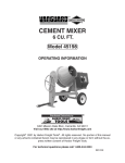
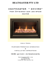
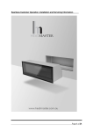
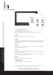
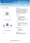
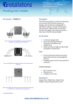
HeatMaster®
Installation, Operating and
Servicing Instructions
HeatMaster® 200 N
HeatMaster® 200 F
excellence in hot water
04/03/2004 - 66412600
INDEX
INTRODUCTION
INTRODUCTION
1
TARGET GROUP
Target group
Symbols
Certification
Information and safety instructions
1
1
1
2
This manual is intended for the use of:
- final users of the appliance;
- the engineer installing and starting up the appliance;
- the engineering and design department;
- the installer responsible for servicing or maintaining the appliance.
USER GUIDE
2
Use of the boiler
2
SYMBOLES
The following symbols are used in this manual:
DESCRIPTION
3
Operating principle
Packing
Construction features
3
3
4
TECHNICAL SPECIFICATION
5
Effective dimensions
General characteristics
Hot water output data
Limits of operating conditions
Burner chamber plate
5
5
6
6
6
INSTALLATION
7
Essential instruction for operating the system
correctly.
Essential instruction for personal safety or
environmental protection.
Boiler room
Chimney connections
Hot water connections
Heating connection
Oil supply connections
Electrical connections
Wiring diagram
7
7
8
9
9
10
10
COMMISSIONING
11
Filling the hot water and heating circuits
11
MAINTENANCE
11
Service intervals
Servicing the boiler
Servicing the safety devices
Servicing the burner
Draining the boiler
11
11
11
11
12
SAFETY MODE
12
Placing the burner in safety mode
Placing the boiler in safety mode
12
12
Risk of scalding.
SPARE PARTS
13
CERTIFICATION
Jackets
Accessories
13
13
The appliances carry the “CE” mark, in accordance with the
standards in force in the various countries (European Directive
92/42/CEE “Efficiency”).
SERVICE RECORD
14
Details of the installation
Service notes
14
14
Danger of electrocution.
DANGER
HOT
1
INTRODUCTION
USER GUIDE
GENERAL INFORMATION
AND SAFETY INSTRUCTIONS
USING THE BOILER
General information
This documentation forms part of the items delivered with the
appliance and must be given to the user to keep in a safe place!
This appliance must be serviced and repaired by an approved
installer, in accordance with current standards in force.
ACV declines all liability for any damage caused as a result of
incorrect installation or as a result of the use of components or
connections that are not approved by ACV for this application.
It is compulsory to have your system serviced every
year by a competent engineer. In the event of heavy
use of the boiler, it may require servicing on a more
regular basis than once a year. In this case, contact
your installer for advice.
Starting the burner
In conditions of normal operation, the burner starts automatically if
the temperature of the boiler is below the set point and goes off
when this value is reached.
Temperatures
Control panel
DANGER
This boiler is designed for central heating systems
with a maximum outlet temperature of 90°C.
Therefore, the central heating pipelines and the
radiators must reach this temperature.
HOT
The waste-gas pipe lines
temperatures in excess of 100°C.
must
reach
Combined temperature
and pressure gauge
Burner
lockout
indicator
Manual reset high
limit thermostat
Time clock
The hot water can reach temperatures in excess
of 60°C.
Installation
I
O
Before installing and commissioning the boiler, first
carefully read this manual.
Position the HeatMaster® according to the safety rules and
standards in force. You must comply with the ventilation
requirements for the room where appliances of this type are
installed. All air vents must remain unobstructed at all times.
It is prohibited to modify the interior of the appliance in any way,
without the manufacturer’s prior written agreement.
Primary circuit low
water pressure
indicator
ON / OFF
switch
Control
thermostat
High limit cutoff
indicator
Summer / Winter switch
Service
In order to ensure the appliance operates safely and correctly, it is
important to have it serviced and reconditioned every year by an
installer or an approved service company.
The user must not attempt to gain access to the
components inside the control panel.
Faults
Despite the strict quality standards imposed on its appliances by
ACV during production, inspection, and transport, faults may occur.
Please immediately inform your approved installer about such faults.
Remember to give the fault code as it appears on the screen.
Only genuine factory parts may be used as replacement parts.
Please go to page 13 for a list of spare parts and their ACV
reference numbers.
Important note: ACV reserves the right to change the technical
characteristics and specification of its products without notice.
1. On/Off switch
This turns the HeatMaster on or off.
2. Control thermostat - 60 to 90°C
When using the HeatMaster® as a hot water generator only, the
temperature can be set between 60°C and 90°C.
If the HeatMaster® is used for both hot water and central heating, the
control thermostat would normally be set at 80°C to achieve optimum
operating conditions.
3. Summer/Winter switch
This turns the heating pump (if fitted) on or off.
4. Manual reset high limit thermostat
If the boiler temperature exceeds 103°C this safety device will
activate and the high temperature indicator will light up. To reset first allow the boiler to cool to below 60°C, unscrew the cap and
press the reset button using a pencil or similar pointed device,
replace the cap. If the fault persists, turn the boiler off and call an
engineer.
2
USER GUIDE
DESCRIPTION
5. Time clock
This allows the HeatMaster® to be timed on and off and operates on
a 24 hour sequence. Around the outside of the clock there are a
number of white tabs, these allow 15 minute switching periods. To
set the time clock simply push outwards the number of tabs required
for ON period.
Remember:
TAB IN = HeatMaster OFF
TAB OUT = HeatMaster ON
6. Temperature and pressure gauge
This gauge indicates both the temperature of the HeatMaster® and
the pressure within the primary circuit.
The temperature should not exceed 90°C - if it does, switch the
boiler off and check the thermostat setting. If the fault persists, call
an engineer.
The pressure should not fall below 1bar, if it does the please see the
'Heating System Pressure' paragraph later in this section.
7. Low primary water pressure indicator
If this indicator lights up, the primary circuit of the HeatMaster®
requires topping up with water. Please see the 'Heating System
Pressure' paragraph later in this section.
Heating-system pressure
The heating circuit may require a top-up of water. The pressure
gauge, located beside the display, gives the pressure.
In the case of repeated fills, contact your installer.
The pressure of the primary circuit must be at least 1 bar and must
be regularly checked by the end user. If the pressure falls below
0.5 bar, the low-water-level pressure switch locks the appliance until
the pressure in the system returns to above 0.8 bar.
The HeatMaster® 200 N / 200 F is fitted with a purpose-designed fill
set (see Fig. A and B). Always make sure that the appliance is
switched off when filling the system.
To do this, turn the On/Off switch on the left of the control panel to
Off.
For more information, please ask your installer when delivering the
system.
The appliance is fitted with a safety valve. If the system pressure
exceeds 3 bars, this valve opens and drains the water from the
system. In this case, contact your installer.
OPERATING PRINCIPLE
The HeatMaster® is a high performance, direct fired hot water
storage heater, which has indirect heat transfer due to its Tank-inTank construction.
At the heart of the HeatMaster® is a stainless steel cylinder through
which the flue tubes pass. This is surrounded by a mild steel shell
containing the primary water (neutral fluid). The outer shell extends
down to the combustion chamber and even around the flue tubes.
The area of the heat transfer surface is therefore much greater than
that of standard direct fired water heaters.
A circulating pump fitted to the primary circuit moves the water
around the tank, heating it faster and maintaining an even
temperature across the primary jacket.
The burner, either gas or oil, fires onto the primary water which
indirectly heats the stainless steel cylinder containing the DHW. As
with all Tank-in-Tanks, this is corrugated over its full height and
suspended in the HeatMaster® by its hot and cold water
connections.
The cylinder expands and contracts during use and this, together
with the fact that cold water does not come into contact with the
intense heat of the burner flame, means that limescale buildup is
prevented.
This scale resistant feature, along with the corrosion resistance of
stainless steel, eliminates the need for sacrifical anodes.
The HeatMaster® has one very major advantage over other direct
fired water heaters - because it heats the DHW with a primary
circuit, this primary water can be used to provide central heating as
well.
By connecting two, three, four or more HeatMaster® together in a
module, most hot water and heating demands can be met.
Indeed, when used in conjunction with HR and Jumbo hot water
storage tanks the HeatMaster can supply even the largest hot water
requirement.
Standard equipment
The HeatMaster 200 has the following items as standard:
- On/off switch
- Summer/Winter switch
- Control thermostat (60 - 90°C)
- Thermal reset high-limit thermostat (95°C)
- Manual reset high-limit thermostat
- Hot water priority thermostat
- Primary circulating shunt pump
- Primary expansion vessels
- Primary safety valve
- Pressure and temperature gauge
- Drain valve
- Body completely insulated in rigid polyurethane foam
PACKING
The HeatMaster is delivered in separate packages.
Fig. A
(cover)
Fig. B
(rear panel)
• Package No. 1:
• Package No. 2:
• Package No. 3:
• Package No. 4:
Foam-insulated body, hydraulic accessories,
and control panel.
Chimney reducing pipe.
Wooden protective casing (jacket and
accessory).
“RIELLO” RG4S 396 T1 burner (HM 200 F only).
3
DESCRIPTION
CONSTRUCTION FEATURES
Outer body
1
5
The outer body, containing the primary water, is made from STW 22
carbon steel.
TANK-IN-TANK heat exchanger
The ring-shaped inner tank with its large heating surface for
producing domestic hot water is built of Chrome/Nickel 18/10
stainless steel. It is corrugated over its full height by an exclusive
production process and entirely argon arc welded by the TIG
(Tungsten Inert Gas) method.
6
2
Combustion gas circuit
The combustion gas circuit is paint-protected and comprises:
• Flue pipes
7
Depending on output, HeatMaster® 200 models contain
several steel flue pipes with an internal diameter of 64 mm.
Each pipe is fitted with a baffle of special steel designed to
improve heat exchange and reduce flue gas temperature.
• Combustion chamber
3
The combustion chamber on HeatMaster® models is entirely
water cooled.
8
Insulation
The boiler body is fully insulated by rigid polyurethane foam with a
high thermal insulation coefficient, sprayed on without the use of
CFCs.
4
Casing
The boiler is covered by a steel jacket which has been scoured and
phosphated before being stove enamelled at 220°C.
9
Burner
The HM 200 F model is always delivered with a “RIELLO” RG4S 396
T1 fuel oil burner.
Legend
1.
“Tank-in-Tank” type storage exchanger
2.
Flue ways
3.
Primary circuit
4.
Combustion chamber
5.
Turbulators
6.
Heating outlet
7.
Stainless steel pocket
8.
Heating return
9.
Boiler drain cock
10. Hot water priority thermostat bulb
10
15
16
11
17
12
11. Cold water inlet
18
12. Bulbs of the thermal reset high-limit 95°C thermostat and the
manual reset high-limit 103°C thermostat
13. Insulation
14. Low-water-level pressure switch
13
19
15. Hot water outlet
16. Chimney reducer
17. Steam trap
18. T&P valve (optional)
19. Thermostat-pressure gauge bulb
14
20
20. 60 - 90°C control thermostat bulb
21. Flange of the burner chamber plate
21
4