1
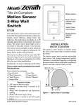
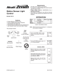
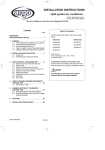
SL-6107
MOTION SENSING
3-WAY WALL SWITCH
The Heath®/Zenith Motion Sensing 3-Way Wall
Switch automatically controls indoor lighting:
• In AUTO mode, the control automatically turns
the light on when you enter the room. The length
of time the light stays on is adjustable.
The Heath®/Zenith SL-6107 Motion Sensing 3-Way
Wall Switch replaces any “3-way” switch. Perfect
for rooms or hallways where two wall switches
control a single light.
This package includes:
• light control
• wire connectors
• wire jumper
• decorative cover plate
• mounting hardware
© 2003 DESA Specialty Products™
OFF
AUTO
ON
595-4514-13
Some local building codes may require installation by a qualified electrician.
INSTALLATION
❐ For your safety, turn off power at the fuse or circuit breaker.
Note: A “3-way” circuit controls lights from two separate switches.
If you want to use this product in a single switch circuit or if you want
to install more than one motion sensing wall switch, see Special
Installations, page 8.
❐ Select a 3-way circuit that controls a light or an outlet to a lamp.
Total lighting must be from 25 to 500 watts incandescent, or 60
to 400 watts fluorescent using a rapid start ballast. Note: May
not be used to operate electronic or magnetic ballasts. Less
wattage than the minimum may not allow the control to work
properly. The switch selected for replacement should be in a place
that can detect motion in the desired area.
✓ For easier re-wiring later, mark the house wiring with tape
indicating where the wire had been connected.
In the following section you will install a jumper wire at one 3-way
switch and replace the other switch with the SL-6107.
*Note: The existing 3-way switch will be referred to as the “Remote
Switch” throughout the rest of the installation manual.
-2-
595-4514-13
INSTALLATION
See pages 4 through 6 for detailed instructions for installing and
wiring the SL-6107 Wall Switch.
EXISTING LIGHT SWITCH CONFIGURATION
WHITE
FROM
POWER
SOURCE
WHITE
WHITE
*COMMON
BLACK
*COMMON
RED
(In Wall)
BLACK
BLACK
SL-6107 SWITCH 1ST ON CIRCUIT
WHITE
WHITE
WHITE
FROM
POWER
SOURCE
ADD JUMPER WIRE
*COMMON
BLACK BLACK
BROWN
OFF
AUTO
RED
(In Wall)
ON
RED
(From 6107)
SL-6107
BLACK
BLACK
EXISTING
3-WAY SWITCH
SL-6107 SWITCH 2ND ON CIRCUIT
WHITE
WHITE
WHITE
FROM
POWER
SOURCE
ADD JUMPER WIRE
BLACK
*COMMON
RED
(In Wall)
BROWN
BLACK
RED
(From 6107)
BLACK
OFF
EXISTING
3-WAY SWITCH
AUTO
ON
BLACK
SL-6107
*COMMON-Used for illustrative Purposes Only. Check Your Switch. The common may be in a different
location, depending on the brand of your switch.
RED is used to represent the second wire between two standard three-way switches. This may not be the
color used in all installation. If you are not sure about your wiring, call an electrician for installation help. There
is also a RED wire on the SL-6107 switch. Check the instructions above closely and do not confuse the two.
595-4514-13
-3-
INSTALLATION
1. Add Jumper At Remote 3-Way Switch.
A jumper wire between the common wire and one of the switched
wires is used to supply power to the SL-6107 regardless of the
position of the remote switch.
❐ Remove remote switch from the junction box.
The switch may
indicate the
common
Common Switch Lug
COMMON
Hot Wire
OR
Jumper
Color of screw may
be different for the
common
To brown wire of
SL-6107 (note color)
To Red wire of SL-6107
(note color)
Connect Jumper at the Remote Switch
❐ Connect the jumper wire to the common lug (usually labeled on
the switch) and to either one of the two switched lugs. If you're
not sure which lug is common, install the jumper on any two of the
wires, and test the jumper as explained on the next page.
-4-
595-4514-13
INSTALLATION
2. Replace Other Switch.
❐ Turn the power off at the circuit breaker.
❐ Remove and disconnect the old switch.
Note: If you can't tell which wire is common, etc., connect the wires
in the following steps as best you can, then follow the test on the
next page.
❐ Connect the black motion sensor wire to the common wire.
❐ Connect the brown motion sensor wire to the jumpered wire on
the remote switch.
❐ Connect the red motion sensor wire to the non-jumpered wire.
❐ Connect the green motion sensor wire to the ground wire.
Jumpered Wire
Brown
Non-Jumpered
Red
Wire Removed
from Common
OFF
Ground Wire
(Green or Bare Wire)
Green
Black
Connect the SL-6107 to Existing Wiring
595-4514-13
-5-
AUTO
ON
INSTALLATION
Test For Correct Common Wire Connection:
Re-install the switch.
Turn the circuit
breaker back on.
Leaving the jumpered switch in one position,
flip the other 3-way switch on and off.
Lights
turn on
and off.
Yes
Jumper is
correct. Go
to next page.
No
Flip the switch with the
jumper wire to the
other position.
Move one end of the jumper
wire to the previously
unconnected terminal.
Flip the unjumpered switch
on and off.
Remove the jumpered
switch from the
junction box.
Turn the power
off at the
circuit breaker.
No
Lights
turn on
and off.
-6-
Yes
Jumper is
correct. Go
to next page.
595-4514-13
INSTALLATION
❐ Mount the SL-6107 into the junction box with the two junction box
screws.
❐ Turn the circuit breaker back on.
❐ Preset the controls: Time to min. (fully counter-clockwise), Photo
Adjustment fully clockwise. Cover the lens with masking tape.
❐ With the motion sensor in the “ON” position, turn the remote
switch on and off several times. Go to step 1, 2, or 3, depending
on results.
Troubleshooting Wiring Connections
* Turn power off before rewiring!
1.
If light does
not turn on:
2.
If light turns on in
only one position
of remote switch:
3.
If light turns on
with remote
switch in either
position:
➯
Exchange*
Control's
Red ⇔ Black
wires.
➯
Test again. Go
to 2 or 3.
➯
Exchange*
Control's
Red ⇔ Brown
wires.
➯
Test again. Go
to 1 or 3.
➯
Set sensor to “AUTO”. Wait for the
unit to warm up (up to 1 min.). If
the remote switch can turn the
lights on, it's OK. Otherwise:
➯
Exchange* Control's
Black ⇔ Brown wires. Remove
the tape. Go to the next page.
595-4514-13
-7-
SPECIAL INSTALLATIONS
For single switch installations, connect
the wall switch as
shown here.
SINGLE SWITCH INSTALLATION
BLACK
BROWN
BLACK
FROM
POWER
SOURCE
OFF
ON
AUTO
BLACK
RED
SL-6107
WHITE
If you want to have motion sensors at both
3-way switches, connect them as shown
below. The minimum
wattage may increase
to 100 W for fluorescent and 50 W for incandescent lighting.
WHITE
EXISTING LIGHT SWITCH CONFIGURATION
WHITE
FROM
POWER
SOURCE
BLACK
WHITE
*COMMON
WHITE
*COMMON
RED
(In Wall)
BLACK
BLACK
2 SWITCH INSTALLATION
FROM
WHITE
POWER
SOURCE
WHITE
BROWN
WHITE
BROWN
BLACK
BLACK
BLACK
RED
(From 6107)
OFF
AUTO
OFF
ON
SL-6107
RED
(From 6107)
AUTO
ON
BLACK
SL-6107
RED (In Wall)
*COMMON-Used for illustrative Purposes Only. Check Your Switch. The common may be in a different
location, depending on the brand of your switch.
RED is used to represent the second wire between two standard three-way switches. This may not be the
color used in all installation. If you are not sure about your wiring, call an electrician for installation help. There
is also a RED wire on the SL-6107 switch. Check the instructions above closely and do not confuse the two.
-8-
595-4514-13
ADJUSTMENT
PHOTO SENSITIVITY
20 Minutes
Any Light Level
ON
OFF
+
AUTO
Press in with screwdriver.
Swing out cover to remove.
TIME
Dark
+
LIGHT
5 Seconds
The sensor can be prevented from turning on lights when there is
already enough light in the room. Use a small screwdriver to set the
light level using this diagram as a guide. In the fully clockwise
position, the sensor turns on lights even in full daylight. In the fully
counter-clockwise position, the sensor only turns on lights when
the surrounding light level is very low.
❐ With the switch in the AUTO position and the light at the desired
level for the lights to turn on, put the LIGHT control to the
minimum dark (fully counter-clockwise) position. Wait for the
lights to turn off.
❐ Move your hand in front of the sensor. While moving your hand
in front of the sensor, slowly turn the LIGHT adjustment clockwise until the lights controlled by the sensor come on.
595-4514-13
-9-
ADJUSTMENT
TIME CONTROL
The time control sets how long the light stays on after motion is
detected or the remote switch is flipped.
❐ Turn the control clockwise to
20 Minutes
5 Seconds
increase the time up to about
20 minutes.
❐ Turn the control counter-clockwise to decrease the time to
about 5 seconds.
Use a small screwdriver to set the
control.
+
INSTALL WALL COVER
PLATE
❐ Secure the included wall plate
with the screws provided.
AUTO
ON
OFF
Outlet Cover Plate
-10-
595-4514-13
OPERATIONS
USING THE LIGHT CONTROL
One of three functions can be selected by using the three-position
switch on the SL-6107:
Off:
When you want the light off all the time.
The light will not be switched on by either switch. Put the control
in this position when changing light bulbs.
Auto: When you want the light to come on and turn off
automatically with motion or turn on with remote
switch.
The control will switch the light on when motion is detected. If no
further motion is detected, the light will turn off after the pre-set time
period. To turn the light on again, move in the detection zone.
Flipping the remote switch up or down will turn the light on for the
pre-set time period.
On:
When you want the light on all the time.
In this position, the light will remain on all the time, daytime and
night. Flipping the remote switch will not affect the light. The Photo
shut-off is also inactive.
595-4514-13
-11-
TROUBLESHOOTING
Light will not come on:
• Circuit breaker is off. Turn breaker back on.
• Bulb is burned out. Replace light bulb.
• Photo Sensitivity is set to DARK. Rotate the adjustment clockwise towards the LIGHT position.
• Control is in the “Off” position. Set to Auto or On.
• Control may be wired incorrectly. See Troubleshooting Wiring
Connections, page 7.
Light will not turn off:
• Control is in the “On” position. Set to Auto or Off.
• Control time period set too long. Set to shorter time period.
• Control may be wired incorrectly. See Troubleshooting Wiring
Connections, page 7.
Remote switch does not work:
• The remote switch only works to turn the light on in the Auto
mode. Put sensor in the Auto mode.
• Control may be wired incorrectly. See Troubleshooting Wiring
Connections, page 7.
In Auto mode, light comes on randomly:
• Objects in detection area which heat and cool, such as air vents
or appliances, may trigger the control. Also, check wiring. See
Troubleshooting Wiring Connections, page 7.
• The remote switch may have been flipped on.
In the Auto mode, light does not turn on:
• If there is too much light already in the room, the light may not
come on. Turn the Photo control clockwise towards the any light
level position.
-12-
595-4514-13
TROUBLESHOOTING
In the Auto mode, light does not stay on:
• Motion is needed to keep the light on.
• Time control is adjusted for too little time. Turn the Time control
clockwise. Note: In the minimum time position, fluorescent lights
may not have enough time to turn on.
In the Auto mode, light turns on in daylight:
• Photo adjustment not set properly. Turn the Photo control counterclockwise towards the DARK position.
TECHNICAL SERVICE
(Do Not Send Products)
If you experience a problem, follow this guide. You may also want
to visit our Web site at: www.desatech.com. If the problem
persists, call* for assistance at 1-800-858-8501, 7:30 AM to 4:30
PM CST (M-F). You may also write* to:
DESA Specialty Products™
P.O. Box 90004, Bowling Green, KY 42102-9004
ATTN: Technical Service Specialty Products
* If contacting Technical Service, please have the following information available: Model Number, Date of Purchase, and Place of
Purchase.
No Service Parts Available for this Product
595-4514-13
-13-
SPECIFICATIONS
This product is to be installed indoors only.
Electrical Input .......................................................... 120V, 60 Hz.
Fluorescent* Load ...................................... (2) 30 Watt minimum,
Up to 400 Watts Maximum Rapid Start Ballast
Motor Load ............................................... Up to 1/8 HP Maximum
Incandescent .................................... Up to 500 Watts at 120VAC
On-Time .................... Adjustable approximately 5 sec. to 20 min.
Photocell Sensor ................. From full daylight to less than 1 FC.
Coverage ........................................... up to 15 ft. (4.6 m) at 150°,
up to 30 ft. (9.1 m) in front of the sensor
Specification subject to change without notice.
*Designed for use with standard 3 ft./30 watt and 4 ft./40 watt rapidstart fluorescent tubes. Not designed for use with compact
fluorescent bulbs.
Minimum of two tubes required. Note: May not be used to operate
electronic or magnetic ballasts.
DESA Specialty Products™ reserves the right to discontinue products and to change specifications at any time without incurring any
obligation to incorporate new features in previously sold products.
-14-
595-4514-13
FIVE YEAR LIMITED WARRANTY
This is a “Limited Warranty” which gives you specific legal rights. You
may also have other rights which vary from state to state or province to
province.
For a period of five years from the date of purchase, any malfunction
caused by factory defective parts or workmanship will be corrected at no
charge to you. Light bulbs are not covered. To obtain a refund or a
replacement, return the product to the place of purchase.
Not Covered - Repair service, adjustment and calibration due to misuse,
abuse or negligence, light bulbs and other expendable items are not
covered by this warranty. Unauthorized service or modification of the
product or of any furnished component will void this warranty in its
entirety. This warranty does not include reimbursement for inconvenience, installation, setup time, loss of use, or unauthorized service.
This warranty covers only DESA Specialty Products™ assembled
products and is not extended to other equipment and components that
a customer uses in conjunction with our products.
THIS WARRANTY IS EXPRESSLY IN LIEU OF ALL OTHER WARRANTIES, EXPRESS OR IMPLIED, INCLUDING ANY WARRANTY, REPRESENTATION OR CONDITION OF MERCHANT ABILITY OR THAT THE
PRODUCTS ARE FIT FOR ANY PARTICULAR PURPOSE OR USE, AND
SPECIFICALLY IN LIEU OF ALL SPECIAL, INDIRECT, INCIDENTAL, OR
CONSEQUENTIAL DAMAGES.
REPAIR OR REPLACEMENT SHALL BE THE SOLE REMEDY OF THE
CUSTOMER AND THERE SHALL BE NO LIABILITY ON THE PART OF
DESA SPECIALTY PRODUCTS™ FOR ANY SPECIAL, INDIRECT, INCIDENTAL, OR CONSEQUENTIAL DAMAGES, INCLUDING BUT NOT
LIMITED TO ANY LOSS OF BUSINESS OR PROFITS, WHETHER OR
NOT FORESEEABLE. Some states or provinces do not allow the exclusion
or limitation of incidental or consequential damages, so the above limitation
or exclusion may not apply to you. Retain receipt for warranty claims.
595-4514-13
-15-
SL-6107
INTERRUPTOR TRIDIRECCIONAL
DE PARED Y DECTECTOR DE
MOVIMIENTO
El Interruptor Tridireccional de pared y Dectector de
Movimiento controla automáticamente la iluminación interna:
• En la modalidad de AUTO, el control
automáticamente prende la luz cuando usted entra
al cuarto. El período de tiempo que la luz se queda
prendida es ajustable.
El Interruptor Tridireccional de pared y Dectector de
Movimiento SL-6107 reemplaza a cualquier interruptor tridireccional. Perfecto para cuartos o pasillos
donde dos interruptores de pared controlan una sola luz.
Este paquete tiene:
• el control de luz
• los conectores de alambre
• los cables de puente
• la placa cubertora decorativa
• los herrajes de montaje
OFF
© 2003 DESA Specialty Products™
-16-
AUTO
ON
595-4514-13
595-4514-13
S
Algunos códigos locales de construcción pueden requerir
que la instalación sea hecha por un electricista calificado.
INSTALACION
❐ Para su seguridad, apague la energía en el fusible o en el
cortacircuitos.
Nota: un circuito “tridireccional” es un circuito de luz controlado
desde dos interruptores separados. Si desea usar este producto
con un circuito de un solo interruptor vea Instalaciones Especiales,
página 23.
❐ Escoja un circuito de 3 direcciones que controle una luz o un
enchufe de lámpara.
El alumbrado total debe estar entre 25 a 500 vatios incandescentes, o entre 60 a 400 vatios fluorescentes usando un estabilizador de arranque rápido. Nota: Puede que no se use para
hacer funcionar estabilizadores electrónicos o magnéticos.
Un vatiaje menor del mínimo no permitirá que el control funcione
correctamente. El interruptor seleccionado para cambiar debería
estar en un lugar que puede detectar movimiento en la área
deseada.
✓ Para facilitar la instalación y el cableado más tarde, use
cinta elécrica en los cables y marque de dónde viene cada
uno.
En la siguiente sección usted instalará un puente de alambre en el un
interruptor de 3-vías y reemplazará el otro interruptor con el SL-6107.
*Nota: Al interruptor existente de 3 direcciones se le llamará
“interruptor remoto” durante el resto del manual de instalación.
595-4514-13
-17-
INSTALACION
Vea en las páginas 19 a 21 las instrucciones detalladas para la
instalación y cableado del interruptor de pared SL-6107.
DISPOSICIÓN DEL INTERRUPTOR DE LA LÁMPARA EXISTENTE
DE LA
FUENTE DE
ALIMENTACIÓN
BLANCO
BLANCO
BLANCO
*COMÚN
NEGRO
*COMÚN
ROJO
(en la
pared)
NEGRO
NEGRO
INTERRUPTOR SL-6107 1ro EN EL CIRCUITO
BLANCO
BLANCO
BLANCO
AÑADA EL
CONDUCTOR PUENTE
DE LA
FUENTE DE
ALIMENTACIÓN
*COMÚN
NEGRO NEGRO
OFF
AUTO
MARRÓN
ROJO
(en la
pared)
ROJO
(Desde
el 6107)
NEGRO
ON
SL-6107
NEGRO
INTERRUPTOR
DE 3-VÍAS EXISTENTE
INTERRUPTOR SL-6107 2do EN EL CIRCUITO
BLANCO
BLANCO
BLANCO
AÑADA EL
DE LA
CONDUCTOR PUENTE
FUENTE DE
*COMÚN
ALIMENTACIÓN
NEGRO
ROJO
(en la
pared)
MARRÓN
NEGRO
ROJO
(Desde
el 6107)
NEGRO
OFF
INTERRUPTOR
DE 3-VÍAS EXISTENTE
AUTO
ON
NEGRO
SL-6107
*COMÚN- Usado sólo por razones ilustrativas. Revise su interruptor. El común puede estar en una
ubicación diferente, dependiendo de la marca de su interruptor.
ROJO- Se usa para representar el segundo conductor entre los dos interruptores estándar de 3-vías. Este
puede no ser el color usado en toda la instalación. Si no está seguro de su cableado, llame a un electricista
para que le ayude en la instalación. Hay también un conductor ROJO en el interruptor SL-6107. Revise
con más detenimiento las instrucciones de arriba para no confundir los dos.
-18-
595-4514-13
INSTALACION
1. Una el cable de conexión al interruptor tridireccional
a control remoto.
Se usa un cable de conexión entre el alambre común y uno de los
alambres con interruptor para suplir energía al SL-6107 cualquiera
sea la posición del interruptor a control remoto.
❐ Quite el interruptor a control remoto de la caja de empalme.
El interruptor puede
indicar el común
Orejeta de interruptor común
COMMON
OR
Cable caliente
El color del tornillo
puede ser diferente
para el común
Cable Conector
Al alambre marrón
del SL-6107 (Note
el color)
Al alambre rojo del SL-6107
(Note el color)
Conecte el Cable Conector en el Interruptor a Control
Remoto
❐ Conecte el puente de alambre al borne común (generalmente
identificado en el interruptor) y a cualquiera de los otros bornes del
interruptor. Si no sabe cuál es el alambre común, instale el cable
conector en cualquiera de los alambres, complete la instalación y
pruebe el cable conector como se explica a continuación.
595-4514-13
-19-
INSTALACION
2. Instale el Detector de Movimiento en el otro
interruptor.
❐ Apague la energía en el cortacircuitos.
❐ Quite y desconecte el interruptor viejo.
Nota: Si no sabe cuál es el alambre común, etc., en los pasos que
siguen, conecte los alambres lo mejor que pueda y haga luego la
prueba que se indica en la página siguiente.
❐ Conecte el alambre negro del detector de movimiento al alambre común.
❐ Conecte el alambre marrón del detector de movimiento al
alambre conectado del interruptor a control remoto.
❐ Conecte el alambre rojo del detector de movimiento al alambre
con interruptor.
❐ Conecte el cable verde del detector de movimiento al cable de
conexión a tierra.
Alambre Conectado
Marrón
Que va sin el
puente
Rojo
Conductor retirado
del común
OFF
AUTO
ON
Verde
Alambre de conexión a tierra
(Verde o conductor desnudo)
Negro
Conecte el SL-6107 a la conexión existente
-20-
595-4514-13
INSTALACION
Prueba para la conexión correcta de un cable común
Reinstale el interruptor.
Prenda de nuevo el
cortacircuitos.
Dejando el cable con puente en una posición,
prenda y apague el otro interruptor tridireccional.
La luz
se prende y
se apaga.
Sí
El puente está
bien. Vaya a la
página siguiente.
No
Mueva el interruptor con
el cable de puente a la
otra posición.
Mueva un extremo del cable
de puente al terminal anterior
desconectado.
Prenda y apague el
interruptor sin puente.
Quite el interruptor
con puente de la
caja de empalmes.
Apague la
energía en el
cortacircuitos.
595-4514-13
No
La luz
se prende y
se apaga.
-21-
Sí
El puente está
bien. Vaya a la
página siguiente.
INSTALACION
❐ Monte el SL-6107 dentro de la caja de empalme con los tornillos
para la caja de empalme.
❐ Instale de nuevo el interruptor.
❐ Prefije los controles: Tiempo Mín. (completamente hacia la
izquierda), Ajuste de foto completamente hacia la derecha.
Cubra la lente con una cinta protectora.
❐ Con el detector de movimiento en posición de prendido (ON)
prenda y apague el control remoto varias veces. Vaya al paso 1,
2 ó 3 dependiendo de los resultados.
Conexiones de cableado para análisis de averías
* Apague la energia antes de reconectar!
1.
2.
3.
Si la luz no se
prende:
Si la luz se prende
solo cuando el
interruptor a
control remoto
está hacia arriba o
hacia abajo:
Si luz con el
interruptor a
control remoto en
cualquier posición:
➯
Cambie* los
alambres Rojos
y Negros del
Control.
➯
Pruebe de
nuevo. Vaya al
2 ó al 3.
➯
Cambie* los
alambres Rojos
y Marrón del
Control.
➯
Pruebe de
nuevo. Vaya al
1 ó al 3.
➯
Fije el detector a la fase de “AUTO”.
Espere hasta que el aparato se
calienta (hasta 1 min.). Si el interruptor remoto puede prender la luz, está
bien. De otra forma:
➯
Cambie* los controles Cables Negro
⇔ Marrón Quite la cinta. Vaya a la
siguiente página.
-22-
595-4514-13
INSTALACIONES ESPECIALES
Para instalaciones
de un solo interruptor conecte el interruptor de pared como
se muestra aquí.
INSTALACIÓN DE UN SOLO INTERRUPTOR
NEGRO
MARRÓN
NEGRO
DE LA
FUENTE DE
ALIMENTACIÓN
OFF
AUTO
NEGRO
ROJO
ON
SL-6107
BLANCO
Se pueden instalar
dos detectores de
movimiento en cada
interruptor de 3 direcciones como se
muestra abajo. El
vatiaje mínimo requerido puede subir a 100
vatios para luz fluorescente y a 50 vatios para
la incandescente.
BLANCO
DISPOSICIÓN DEL INTERRUPTOR DE LA LÁMPARA EXISTENTE
NEGRO
BLANCO
BLANCO
BLANCO
DE LA
FUENTE DE
ALIMENTACIÓN
*COMÚN
*COMÚN
ROJO
(en la
pared)
NEGRO
NEGRO
INSTALACIÓN DE DOS INTERRUPTORES
BLANCO
DE LA
FUENTE DE
ALIMENTACIÓN
BLANCO
MARRÓN
BLANCO
MARRÓN
NEGRO
NEGRO
NEGRO
OFF
AUTO
ON
ROJO
(Desde el
SL-6107)
OFF
ROJO
(Desde el
SL-6107)
ROJO (en la pared)
SL-6107
AUTO
ON
NEGRO
SL-6107
*COMÚN- Usado sólo por razones ilustrativas. Revise su interruptor. El común puede estar en una
ubicación diferente, dependiendo de la marca de su interruptor.
ROJO- Se usa para representar el segundo conductor entre los dos interruptores estándar de 3-vías. Este
puede no ser el color usado en toda la instalación. Si no está seguro de su cableado, llame a un electricista
para que le ayude en la instalación. Hay también un conductor ROJO en el interruptor SL-6107. Revise
con más detenimiento las instrucciones de arriba para no confundir los dos.
595-4514-13
-23-
AJUSTE
SENSIBILIDAD DE FOTO
20 Minutos
Cualquier nivel de luz
ON
OFF
+
AUTO
Presione con un destornillador.
Gire la tapa para quitarla.
TIME
Obscuro
+
LIGHT
5 Segundos
El detector puede prevenir que se prenda la luz cuando existe ya
suficiente luz en el cuarto. Use un pequeño destornillador para fijar
el nivel de luz usando este diagrama como guía. Cuando está
completamente hacia la derecha, el detector prende la luz aún en
pleno día. Cuando está completamente hacia la derecha, el detector
prender la luz sólo cuando el nivel de luz del alrededor es muy bajo.
❐ Con el interruptor en la posición de AUTO y la luz al nivel deseado
para que la luz se prenda, ponga el control de LUZ (LIGHT) a la
posición obscura mínima (completamente hacia la izquierda).
❐ Mueva su mano frente al detector. Mientras mueve su mano frente
al detector, mueva despacio el ajuste de LUZ (LIGHT) hacia la
derecha hasta que se prenda la luz controlada por el detector.
-24-
595-4514-13
AJUSTE
CONTROL DEL TIEMPO
El control del tiempo determina por cuánto tiempo la luz se quedará
prendida después de que se ha detectado un movimiento o de que
se ha movido el interruptor a control remoto.
❐ Gire el control hacia la derecha
20 Minutos
5 Segundos
para aumentar el tiempo hasta
cerca de 20 minutos.
❐ Gire el control hacia la izquierda para disminuir el tiempo
hasta cerca de 5 segundos.
Use un pequeño destornillador
para fijar el control.
+
INSTALE LA TAPA DE
PARED
❐ Asegure, con los tornillos incluidos, la placa de pared que se
provee.
AUTO
ON
OFF
Tapa de la salida
595-4514-13
-25-
FUNCIONAMIENTO
CÓMO USAR EL CONTROL DE LUZ
Se pueden escoger tres posiciones cuando se usa el interruptor de
tres posiciones del SL-6107:
Off:
Cuando quiere que la luz esté siempre apagada.
La luz no se prenderá con ninguno de los dos interruptores.
Coloque el control en esta posición cuando cambie bombillas.
Auto: Cuando quiere que la luz se prenda y se apague
automáticamente con el movimiento o que se prenda
con el interruptor a control remoto.
El control prenderá la luz cuando se detecte movimiento. Si no se
detecta más movimiento, la luz se apagará después del período de
tiempo predeterminado. Para prender la luz de nuevo, muévalo a
la zona de detección. Si mueve el interruptor a control remoto hacia
arriba o hacia abajo la luz se prenderá por el período de tiempo
predeterminado.
On:
Cuando quiere que la luz esté siempre prendida.
En esta posición la luz permanecerá prendida todo el tiempo,
durante el día y la noche. El uso del interruptor a control remoto no
afectará a la luz. El interruptor de foto está también inactivo.
-26-
595-4514-13
INVESTIGACION DE AVERIAS
La luz no se prende:
• El cortacircuitos está apagado. Préndalo de nuevo.
• La bombilla está quemada. Cambie la bombilla.
• La sensibilidad de foto está fijada en DARK (OBSCURO). Gire el
ajuste hacia la derecha hacia la posición de LIGHT (CLARO).
• El control está en la posición de apagado (OFF). Préndalo (ON)
o póngalo en automático (AUTO).
• El control puede estar conectado incorrectamente. Vea Conexiones
de cableado para análisis de averías, página 22.
La luz no se apaga:
• El control está en la posición de ON (prendido). Apáguelo (OFF)
o póngalo en Automático (AUTO).
• El control está calibrado para un período de tiempo demasiado
largo. Póngalo para un período de tiempo más corto.
• El control puede estar conectado incorrectamente. Vea Conexiones
de cableado para análisis de averías, página 22.
El interruptor a control remoto no funciona:
• El interruptor a control remoto solo prende la luz cuando está en
su fase automática. Ponga el detector en su fase Automática.
• El control puede estar conectado incorrectamente. Vea Conexiones
de cableado para análisis de averías, página 22.
La luz se prende de vez en cuando en automático:
• Aquellos objetos en el área de detección que causan calor o frío,
tales como respiraderos o electrodomésticos, pueden activar el
control. Verifique también el cableado. Vea Conexiones de
cableado para análisis de averías, página 22.
595-4514-13
-27-
INVESTIGACION DE AVERIAS
• Puede ser que se le haya movido al interruptor a control remoto.
La luz no se prende cuando está en automático:
• Si hay demasiada luz en el cuarto, pueda ser que la luz no se
prenda. Gire el control de Foto hacia la izquierda hacia la
posición de LIGHT (claro).
La luz no se queda prendida cuando está en automático:
• Se necesita movimiento para que la luz se quede prendida.
• El control de tiempo está calibrado para un período demasiado
corto de tiempo. Gire el control del tiempo hacia la derecha. Nota:
En la posición de tiempo mínimo, las luces fluorescentes no
tendrán suficiente tiempo para prenderse.
La luz se prende durante el día cuando está en
automático:
• El Ajuste de Foto no está correctamente calibrado. Gire el control
de Foto hacia la derecha hacia la posición de DARK (obscuro).
SERVICIO TÉCNICO
(No enviar los productos)
Si tiene algún problema por favor siga esta guía. Lo sentimos, pero
no podemos contestar preguntas en español por teléfono. Usted
puede también escribir* a:
DESA Specialty Products™
P.O. Box 90004, Bowling Green, KY 42102-9004
* Si se llama al Servicio Técnico, por favor tener lista la siguiente
información: Número de Modelo, Fecha de compra y Lugar de compra.
No hay piezas de servicio disponibles para este
producto
-28-
595-4514-13
ESPECIFICACIONES
Este producto debe ser instalado sólo dentro de casa.
Entrada eléctrica ...................................................... 120V, 60 Hz.
Carga Fluorescente* ..................................... (2) 30 Vatios Mín. y
Hasta 400 Vatios Máximo Estabilizador de arranque rápido
Carga del motor .......................................... Hasta 1/8 HP Máximo
Incandescente ...................................... Hasta 500 Vatios Máximo
Duración ..... Ajustable aproximadamente de 5 seg. a 20 minutos
Detector de fotocélula .. desde luz de pleno día a menos de 1FC
Alcance ....................................................... Hasta 15 pies a 150°,
hasta 30 pies frente al detector
Especificaciones sujetas a cambio sin previo aviso.
* Diseñado para funcionar con los tubos fluorescentes estándar de
rápido encendido de 3 pies/30 vatios y de 4 pies/40 vatios. No está
diseñado para ser usado con bombillas fluorescentes compactas.
Se requiere un mínimo de dos tubos. Nota: Puede que no se use
para hacer funcionar estabilizadores electrónicos o magnéticos.
DESA Specialty Products™ se reserva el derecho de descontinuar
productos y de cambiar especificaciones a cualquier momento sin
incurrir en ninguna obligación de tener que incorporar nuevas
características en los productos vendidos con anterioridad.
595-4514-13
-29-
GARANTÍA LIMITADA A 5 AÑOS
Esta es una “Garantía Limitada” que le da a Ud. derechos legales
específicos. Usted puede también tener otros derechos que varían de
estado a estado o de provincia a provincia.
Por un período de 5 años desde la fecha de compra, cualquier mal
funcionamiento ocasionado por partes defectuosas de fábrica o mano
de obra será corregido sin cargo para Ud. Las bombillas no están
cubiertas. Para obtener el reembolso o reemplazo, devuelva el producto
al lugar de compra.
No cubierto - Los servicios de reparación, regulación y calibración
debidos al mal uso, abuso o negligencia, las bombillas y otras partes
fungibles no se cubren con esta garantía. Los Servicios no autorizados
o modificaciones del producto o de cualquier componente que se provee
invalidarán esta garantía en su totalidad. Esta garantía no incluye
reembolso por inconveniencia, instalación, tiempo de montaje, pérdida
por uso, o servicio no autorizado.
Esta garantía cubre solamente los productos ensamblados por DESA
Specialty Products™ y no se extiende a otros equipos o componentes
que el consumidor usa junto con nuestros productos.
ESTA GARANTÍA ESTÁ EXPRESAMENTE EN LUGAR DE OTRAS
GARANTÍAS, EXPRESADAS O SOBREENTENDIDAS, INCLUYENDO
CUALQUIER GARANTÍA, REPRESENTACIÓN O CONDICIÓN DE
COMERCIABILIDAD O QUE LOS PRODUCTOS SE ADAPTEN PARA
CUALQUIER PROPÓSITO O USO EN PARTICULAR, Y
ESPECIFICAMENTE EN LUGAR DE TODOS LOS DAÑOS
ESPECIALES, INDIRECTOS, INCIDENTALES Y CONSECUENTES.
LA REPARACIÓN O EL REEMPLAZO DEBERÍA SER LA ÚNICA
SOLUCIÓN DEL CLIENTE Y NO HABRÁ RESPONSABILIDAD POR
PARTE DE DESA SPECIALTY PRODUCTS™ POR CUALQUIER DAÑO
ESPECIAL, INDIRECTO, INCIDENTAL O CONSECUENTE, INCLUIDOS
PERO NO LIMITADOS A CUALQUIER PÉRDIDA DE NEGOCIO O
GANACIAS SEAN O NO PREVISIBLES. Algunos estados o provincias no
permiten la exclusión o limitación de daños incidentales o consecuentes,
de modo que la limitación o exclusión arriba indicada puede que no se
aplique a Ud. Guarde el recibo para reclamos de garantía.
-30-
595-4514-13