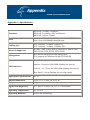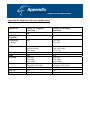
1
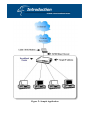
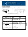
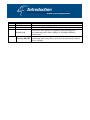
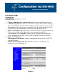
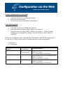
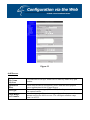
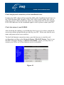
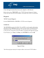
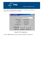
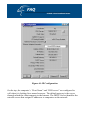
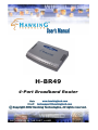
H-BR49
4-Port Broadband Router
Trademarks & Copyright
Windows 95/98/ME and Windows NT/2000/XP are registered trademarks of
Microsoft Corp. All other brands and product names are trademarks of their respective
companies.
No part of this publication may be reproduced in any form or by any means or used to
make any derivative (such as translation, transformation or adaptation) without the
express written consent of the manufacturer as stipulated by the United States
Copyright Act of 1976.
FCC Certifications
This equipment has been tested and found to comply with the limits for a Class B
digital device, pursuant to Part 15 of the FCC Rules. These limits are designed to
provide reasonable protection against harmful interference in a residential installation.
This equipment generates, uses and can radiate radio frequency energy and, if not
installed and used in accordance with the instructions, may cause harmful interference
to radio communications. However, there is no guarantee that interference will not
occur in a particular installation. If this equipment does cause harmful interference to
radio or television reception, which can be determined by turning the equipment off
and on, the user is encouraged to try to correct the interference by one or more of the
following measures:
• Reorient or relocate the receiving antenna.
• Increase the separation between the equipment and receiver.
• Connect the equipment into an outlet on a circuit different from that to which the
receiver is connected.
• Consult the dealer or an experienced radio/TV technician for help.
Shielded interface cables must be used in order to comply with emission limits.
You are cautioned that changes or modifications not expressly approved by the party
responsible for compliance could void your authority to operate the equipment.
This device complies with Part 15 of the FCC rules. Operation is subject to the
following two conditions: (1) This device may not cause harmful interference, and (2)
This device must accept any interference received, including interference that may
cause undesired operation.
CE Mark Warning
This is a Class B product. In a domestic environment, this product may cause radio
interference, in which case the user may be required to take adequate measures.
All trademarks and brand names are the property of their respective proprietors.
Specifications are subject to change without prior notification.
HAWKING LIMITED WARRANTY
Hawking Technology guarantees that every H-BR49 Broadband Router is
free from physical defects in material and workmanship under normal
use for two (2) years from the date of purchase. If the product proves
defective during this two-year warranty period, call Hawking Customer
Service in order to obtain a Return Authorization number. Warranty is
for repair or replacement only. Hawking Technology does not issue any
refunds. BE SURE TO HAVE YOUR PROOF OF PURCHASE.
RETURN REQUESTS CAN NOT BE PROCESSED WITHOUT
PROOF OF PURCHASE. When returning a product, mark the Return
Authorization number clearly on the outside of the package and include
your original proof of purchase.
IN NO EVENT SHALL HAWKING TECHNOLOGY’S LIABILTY EXCEED
THE PRICE PAID FOR THE PRODUCT FROM DIRECT, INDIRECT,
SPECIAL, INCIDENTAL OR CONSEQUENTIAL DAMAGES RESULTING
FROM THE USE OF THE PRODUCT, ITS ACCOMPANYING SOFTWARE
OR ITS DOCUMENTATION. Hawking Technology makes no warranty or
representation, expressed, implied or statutory, with respect to its products or the
contents or use of this documentation and all accompanying software, and
specifically disclaims its quality, performance, merchantability, or fitness for any
particular purpose. Hawking Technology reserves the right to revise or update
its products, software, or documentation without obligation to notify any
individual
or
entity.
Please
direct
all
inquiries
to:
[email protected].
Introduction……………………………………………………………………………5
Factory Default Settings…………………………………………………………….10
Configuration via the Web……………………………………………………….....13
Changing Passwords…………………………………………………………………42
Configuration via GUI……………………………………………………………….43
FAQ…………………………………….…………………………………………….57
Appendix……………………………………………………………………………. 65
The H-BR49 Broadband Router is an integrated Internet IP sharing device with a
built-in 4-port 10/100Mbps N-Way Fast Ethernet switch. It has superb throughput of
up to 35Mbps between Internet and LAN, making it the perfect solution to connect a
small group of PCs to a high-speed broadband Internet connection. Multiple users can
have high-speed Internet access simultaneously via one single IP address (Internet
account) of the Cable/xDSL modem.
This product also serves as an Internet firewall, and thus protects your network from
being accessed by outside users. All incoming data packets are monitored and filtered.
The Router can also be configured to filter internal user access to the Internet.
The built-in 4-port Fast Ethernet Switch lets users plug the network cable into the
device without buying an additional Hub/Switch.
In addition, the unit is equipped with an Incoming Mail Indicator, which will become
lit when there is e-mail waiting to be retrieved at the mail server.
Figure 1: Sample Application
Features
•
•
•
•
•
•
•
•
•
•
•
•
•
•
•
•
•
•
•
•
Superb performance with throughput of up to 35Mbps between
Internet and LAN.
Web and GUI management.
Supports PPPoE.
Supports VPN. (PPTP, IP- Sec pass thru)
Supports Auto MDI/MDIX for the LAN and WAN ports.
Supports rich Internet applications such as MSN, StarCraft, AOE,
Battle.net multi-user, Crazy Arcade, NetMeeting, ICQ, mIRC, Web
browser, FTP, Telnet, E-Mail, News, Ping, PCAnyWhere...
DHCP server allocates up to 253 client IP addresses.
Allows for the setting of 32 Static DHCPs.
Proxy DNS.
Dynamic DNS (DDNS)
Allows for the setting of 24 Virtual Servers.
DMZ host & Multi-DMZ.
Allows for the setting of 24 Packet Filters.
Static routing.
Super manager.
LED indicator for received E-Mail.
Allows firmware upgrade through network.
Supports Windows 95/98/ME/NT/2000/XP, Unix, and Mac.
Natural firewall keeps hackers out.
Load/Save device settings from/to a PC file
Part Names and Functions
LED Indicators on the Front Panel
Ports on the Rear Panel
1 2 3 4 5
6 7
Figure 2: LED Indicators and Ports
1
2
3
to
6
7
LED
Color
Status
Indicator
Color
Solid
Flashing
Green
/Red
Turns solid green when
power is applied to this
device. Turns solid red
when the device is not
working properly.
N/A.
Green
Connected and linked to Receiving/
a Cable/xDSL Modem. Sending data
Power
/Error
WAN
1 (LAN)
2 (LAN)
3 (LAN)
4 (LAN)
New E-Mail
Green
Green
Turns green when linked
Receiving/
to a local network.
Sending data
Flashing frequency (F) vs. Email amount (N)
F = 1 when N < 5
F = 2 when 5 ≤ N < 10
F = 3 when 10 ≤ N < 20
F = 4 when N ≥20
a
b
c
d
Port/button
5V DC
Internet
Functions
Connects the power adapter plug.
Connects to a Cable/xDSL modem.
Four RJ-45 dual-speed (10/100Mbps) auto-sensing ports
for connecting with either 10Mbps or 100Mbps Ethernet
Local (1-4)
connections.
Press for at least 5 seconds to restore to factory settings.
(Factory) RESET Performing the Factory Reset will erase all previously entered
device settings.
Password
Default setting: No password.
Setting up a password: When configuring the device, press Enter to login the
configuration for the first time. It is recommended that you set a password for
security and management purposes.
Password forgotten? If you forget the password, you can reset the device to the
factory setting. Refer to the section titled “Factory Reset” for details.
Local and Global Port Addresses
The LAN parameters for the product are pre-set in the factory. The default
values are shown below.
IP address
Local Port
192.168.1.254
Subnet Mask
DHCP server function
IP addresses for
distribution to PCs
Global Port
The DHCP client
function is enabled
to automatically get
255.255.255.0
the Global port
Enabled
configuration from
the ISP.
253 IP addresses continuing from 192.168.1.1 to
192.168.1.253
Information from ISP
Before you start configuring this device, you should review the information
given in the following tables and use it as a reference.
For CATV dynamic mode:
Some Internet Service Providers (ISP) require that you
register the MAC address of your network card/adapter,
which was connected to your cable or DSL modem during
installation. If your ISPs require MAC address
registration, find your adapter’s MAC address by doing
the following:
Adapter Address
Device/Computer
Name (or Host
Name by some
ISP.)
Domain Name
Using Windows 95 or 98: Click Start Run; type in
“winipcfg”; select the network adapter (not PPP adapter).
Using Windows ME, 2000 or XP: Click Start Run; type
in “command”; press Enter. At the DOS prompt, type
“ipconfig/all”. Look for the Adapter’s “Physical
Address”: a 12-digit HEX number (00-11-22-aa-bb-cc).
Enter a descriptive name for identification purposes. You
may have to check with your ISP to see if your Broadband
Internet service has been configured with a host and
domain name. In most cases, these fields may be left
blank. Some Internet Service Providers (ISP) require this
information and if that is the case, they will provide you
with the name.
Ex. yourcompany.com,
Provided by your ISP.
For DSL dynamic mode:
PPPoE Account
Info
Username
Password
Service Name
Static IP
Address
Static DNS
Server
Provided by your ISP
Provided by your ISP.
Provided by your ISP.
For identification purposes. If it is required, your
ISP will provide you with the information.
Provided by your ISP.
Provided by your ISP.
For Static Mode:
IP address
ISP-assigned IP address
Subnet mask
Gateway
DNS server #1
DNS server #2
Example: 203.66.81.201
Example: 255.255.255.0
Example: 203.66.81.254
Example: 203.66.81.251
Example: 203.66.81.252
Before you start setting up IP Sharing via browser-based web configuration,
make sure that:
• Assuming the workstation’s TCP/IP is set to obtain IP automatically and
the IP Sharing Device’s Local Port is set to “Distribute IP” (default),
and all the cables are connected correctly, you are now ready to
configure this device via Web Browser. Open the browser, enter the
local port IP address (default at 192.168.1.254) of the IP Sharing Device,
and click “Go” to get the login page.
Figure 3
No user name is required. The default password is left blank. If you have set a
password, enter that and click OK to continue.
Figure 4
At the setup home page, the left navigation pane for bookmarks links you
directly to the desired setup page. You can select Global Port, Local Port,
Management, Virtual Server, Packet Filter, Static Router, Checking E-Mail,
Dynamic DNS, Network Status (WAN IP Status, Session List, User
List), Factory Reset, Save Configuration, or Firmware Upgrade. Click on
the desired setup item to expand the page in the main navigation pane. The setup
pages covered in this utility are described below.
WAN Port
The opening screen contains settings for the Global (Internet connection)
interface. Click on the down arrow to select the desired Internet connection
mode on the list.
Obtain configuration automatically
(CATV dynamic mode)
PPPoE (DSL dynamic mode)
Static configuration
For users who are using Cable Modem
Internet service.
For users who are using xDSL Internet
service that runs PPPoE. If your xDSL
service uses PPPoE, after installing the
IP Sharing device, do not run PPPoE
software on your computers.
Select this item when the ISP assigns a
static IP address for your account.
CATV dynamic Mode
Selecting this mode enables you to obtain a dynamic IP address from your ISP
via DHCP support. Once the IP address is obtained, you can access the Internet.
For most cases, this page needs no input. However, some ISPs may require some
information for identification purposes. For example: Device/Computer name
and Domain Name - please enter the information required to complete the
settings.
Check to modify
the MAC address
when necessary.
Figure 5
Device Information
Adapter Address
Device/Computer
Name
Domain Name
IP Config
This field is grayed out because the Adapter Address is not
supposed to be entered randomly. Do Not alter the content
unless you are sure it is necessary to modify your MAC
address. To modify the address, check Modify and enter
the desired MAC address.
Enter a descriptive name for identification purposes. Some
Internet Service Providers (ISP) require this information
and if that is the case, they will provide you with the name.
For example: yourcompany.com. The maximum input
for this field is 32 alphanumeric characters and it is case
insensitive. Note: 1. Your ISP may ask you to input a
certain domain name. 2. A Domain name is also
required for the internal network’s email and news
functions.
This field is grayed out because the IP address is
obtained dynamically.
PPPoE (DSL dynamic Mode)
If this mode is selected and settings are saved, this IP sharing device will be
connected to the Internet over an always-on connection by a method provided by
PPPoE. PPPoE offers simulated dial-up software like Microsoft Dial-Up
Networking, which saves the time and effort required to run the program from a
PC. And the auto-connect/disconnect feature lets the system stay idle when there
is no activity, but pick up the connection in no time when there is network
activity. This can significantly save users’ costs on connection fees.
The TCP MSS function lets you choose the maximum packet size that fits your
need for optimal throughput. Reducing the packet size can help enhance
connection to certain web sites or speed up the packets to be received/sent.
Figure 6
Device Information
Adapter Address
Device/Computer Name
Domain Name
PPPoE Account
Username
Password
This field is grayed out because the
Adapter Address is not supposed to be
entered randomly. Do Not alter the
content unless you are sure it is
necessary to modify your MAC
address. To modify the address, check
Modify and enter the desired MAC
address.
Enter a descriptive name for
identification purposes. Some Internet
Service Providers (ISP) require this
information and if that is the case,
they will provide you with the name.
For example: yourcompany.com. The
maximum input for this field is 32
alphanumeric characters and it is case
insensitive.
Active Profile 1 2 3: You can
set up to three PPPoE accounts, while
only one account can be enabled at a
time. To set the profile, select the
profile number, enter all the
information, and then click on Save.
The device will save the information;
restart and return to the previous menu
page. If you don’t see the saved
information on the screen: from the
menu on the left, click on the “Global
Port” to refresh the screen.
The max. input is 52 alphanumeric
characters (case sensitive).
The max. input is 36 alphanumeric
characters (case sensitive).
Service Name
For identification purposes: if it is
required, your ISP will provide you
with the information.
Max packet size (TCP MSS): Click
the down arrow to select the most
appropriate MSS (maximum segment
size; the default value is 1452) for
your application. Reducing the packet
size can help enhance connection to
certain web sites or speed up packet
transfer rates. If the incorrect selection
is selected, you may not be able to
open certain web sites.
Note that there may be more than one IP address from your ISP; select one
address and enter it in the corresponding field.
Figure 7
Device Configuration
Adapter Address
This field is grayed out because the
Adapter Address is not supposed to be
entered randomly. Do Not alter the
content unless you are sure it is
necessary to modify your MAC
address. To modify the address, check
Modify and enter the desired MAC
address.
Device/Computer Name
Domain Name
IP Address
Subnet Mask
Gateway
Primary/Secondary
SAVE
UNDO
Enter a descriptive name for
identification purposes. Some Internet
Service Providers (ISP) require this
information and if that is the case,
they will provide you with the name.
For example: yourcompany.com. The
maximum input for this field is 32
alphanumeric characters and it is case
insensitive
Enter the information provided by
your ISP.
Enter the information provided by
your ISP.
Enter the information provided by
your ISP.
Enter the information provided by
your ISP.
After completing the settings on this
page, click SAVE to save the settings.
Click UNDO to clear all the settings
on this page.
LAN Port
This screen contains settings for the LAN interface corresponding to the local
network. You can change the setting to distribute the IP address to local PCs, if
desired. If “Distribute IP address to local computer” is selected, users can enter
the IP addresses assigned for the computers on the LAN. The number of IP
addresses decides the number of clients allowed for the assigned IP addresses.
Note that all the PCs on the same LAN should use the same subnet Mask.
Users can also set Static DHCPs on this page. Users are allowed to set 32 Static
DHCPs. Using this feature, the device will assign the same IP address to a
computer (according to the network adapter’s MAC address) and this computer
becomes the only one able to request that IP address. This is quite useful to set
virtual servers which specifically require fixed IPs for outside Internet access.
Figure 8
Private Network
IP Address
Subnet mask
Default: 192.168.1.254 (this is the
local address of this IP Sharing
device)
Default: 255.255.255.0
DHCP Server
Do not distribute IP address to local
computers
Distribute IP addresses to local
computers
Check this radio button to disable this
IP Sharing device from distributing IP
Addresses (DHCP Server disabled)
Check this radio button to enable this
IP Sharing device to distribute IP
Addresses (DHCP enabled). The
following field will be activated for
you to enter the starting IP Address.
Start IP address
Number of IP addresses
Static DHCP IP & MAC address
WINS server
SAVE
UNDO
The starting address of this local IP
network address pool. The pool is a
piece of continuous IP address
segment. Keep the default value at
192.168.1.1, which should work for
most cases.
Maximum: 253. Default value of 253
should work for most cases.
Note: If “Continuous IP address poll
starts” is set at 192.168.1.1 and the
“Number of IP address in pool” is
253, the device will distribute IP
addresses from 192.168.1.1 to
192.168.1.253 to all the computers in
the network that request IP addresses
from the DHCP server (IP Sharing
Device).
Click the ADD button to enter the
Static DHCP page. Enter IP and
Network adapter MAC addresses for
Static DHCP and click the ADD button
to save the settings. Click DELETE
ALL to clear all entries. Click the
Index drop-down menu to select the
desired entry number and then click
DELETE to delete only the selected
server. You can add up to 32 static
DHCP IPs. Click BACK to return to
the Local Port page to continue.
When necessary, enter the IP Address
of the Windows domain name server.
After completing the settings on this
page, click SAVE to save the settings.
Click UNDO to clear all the settings
on this page.
Advanced Setup
Management
In this management page, you can:
1.
2.
3.
4.
5.
Change Administrator’s password: change the password for the device.
Limit Management: Enables two stations to manage this IP Share through
Web configuration. Enter the MAC addresses of the stations you selected for
management. After the setup is completed, only the assigned stations with
correct password authentication can manage this IP Share device.
Block LAN Request: Blocks requests from the Internet to the local network.
If this item is checked, the function of management through Web
configuration will be disabled. In other words, Internet requests and the
HTTP management, namely ICMP, IDENT, and HTTP will be rejected.
Block WAN Request.
Management via Internet: Allows management of this device via HTTP
from the Internet.
Modify the Configuration Port: Enables the user to modify the port
number for web configuration.
Figure 9
Change Administrator’s password:
1.
2.
3.
Click the checkbox to enable this change.
Enter the new password.
Re-enter the new password for confirmation.
Limit Management:
1.
2.
3.
Click the checkbox to enable this function.
Enter the network adapter MAC address for Station 1.
Enter the network adapter MAC address for Station 2. If you are only
setting up one management station, leave the Station 2 MAC address
with all F.
Below are coordinate results of the Block WAN Request and HTTP management
for this device. Refer to this table for further Internet/system management.
V: Checked
O: Unchecked
Block WAN
Request
Management
Via Internet
V
O
(automatically)
O
V
O
O
Coordinate Result
WAN requests over TCP 113 (IDENT) and
ICMP are rejected.
HTTP management is not allowed.
WAN requests over TCP 113 (IDENT) and
ICMP are accepted.
HTTP management is allowed.
WAN requests over TCP 113 (IDENT) and
ICMP are accepted.
HTTP managements is not allowed.
Figure 10
Modify the Configuration Port:
1.
2.
Click the checkbox to enable this function.
Input the port number for web configuration. The default web port for
configuration is set to 80. If you want to change the default setting, input the
appropriate port number. Once the web configuration has been modified,
configuration over the web should be changed with the new setting (e.g., if
the web configuration port is set to 8080, you will need to input the address
as follows to login the web configuration: http://192.168.1.254:8080 (where
192.168.1.254 is your local port IP address).
After changing the settings, click SAVE to save them, or click UNDO to clear all the
settings on this page.
Virtual Server
In this page, you can set up a local server with a specific port number that stands
for the service (e.g. web(80), FTP(21), Telnet(23)). When this device receives an
incoming access request for this specific port, it will be forwarded to the
corresponding internal server. You can add virtual servers either by port number
or by name.
A maximum 24 Server entries are allowed and each port number can only be
assigned to one IP address.
NOTE: Setting up a Virtual Server is like opening the firewall, which exposes
your network to users on the Internet. This means the IP Share’s NAT will no
longer be able to provide protection from hackers.
Figure 11
Add Server
Method:
By Name
By Port
Application
(Port)
Port Type
Single/Range,
Port Number
You can select to set up a virtual server either by name or by port
number.
Select and click ▼ to scroll down. Select from the most popular
server applications for the Virtual Server.
Please select the port type (TCP or UDP) for the port number that
was entered earlier.
For selecting a specific port or a range of ports that you want the
Internet users to be able to access. The valid port numbers range
from 0 to 65535.
UNDO
ADD
Click UNDO to clear all the settings on this page.
Each time you finished setting, click ADD and the added
servers will appear on the Server List.
DELETE ALL
DELETE
Click to delete all the servers on the list.
Click the Index drop-down menu to select the desired server
number and then click DELETE to delete only the selected
server.
DMZ Host
Function:
If the DMZ Host Function is enabled, it means that you can set
up a DMZ host at a particular computer to be exposed to the
Internet so that some applications/software, especially
Internet/online games can have two-way connections. You can
enter up to four DMZ Hosts in the device.
Enter the local IP address mapping to the client computer,
which you will want to use as the DMZ Host computer.
Enter the WAN IP Address set for the DMZ Host.
DMZ LAN IP
Address
DMZ WAN IP
Address
UNDO
ADD
Click to clear all the settings on this page.
After completing the settings on this page, click “ADD” to save
the settings.
DMZ List
Display all the DMZ hosts.
DELETE ALL
DELETE
Click to delete all the DMZ host(s) on the list.
Click on the Index drop-down menu to select the desired host
number and then click DELETE to delete only the selected
host.
Packet Filters
In the Packet Filters setup screen, you can block specific internal users from
accessing the Internet and you can also disable specific Internet services. You
can set up the filters described in the tables that follow. Each filter can be set to
filter (drop) or forward (pass) packets. You can input up to 24 filters into this
device.
Network Adapter Address Filter
IP Address Filter
Single/Range
IP Range
Direction
TCP/UDP Port Filter
Filter according to the local
computer’s network adapter MAC
address (also known as the adapter
card’s Physical Address).
Filter with the computer’s IP address.
You can filter a single IP, or a range
of IP addresses.
Enter the Start and End IP addresses
for a range of IP addresses for
filter/forward.
From Local IP: filtering of an IP
address of a local computer; or
To Remote IP: filtering of an IP
address of a remote server (this
remote server connects to the device
via Internet).
Filter using the port number. You can
set the filter for a single port or a
range of ports.
Filter/Forward
Please note that performing the Factory
Reset will erase all previously entered
device settings.
Single/Range
Port Number
Port Type
Select to Filter or Forward for the
following assigned port(s).
You can filter a single port, or a range
of ports
The port number(s) for the filters.
TCP port: filter according to the
Connection-Based
Application Service on the
remote server using the port
number.
UDP port: filter according to
the Connectionless
Application Service on the
remote server using the port
number.
Figure 12
ADD
UNDO
Filter List
DELETE ALL
DELETE
Every time you finish setting the filters, click the ADD button and the
added filter will appear on the Filter List
Click UNDO to clear all the settings in this category
Displays all the Packet Filters.
Click to delete all the filters on the list.
Click on the Index drop-down menu to select the desired filter
number and then click DELETE to delete only the selected
filter.
Static Router
You can set static routes to manually administrate the network topology/traffic
when the dynamic route is not effective enough.
To set the static routers:
1. Select “Static Route #1” or “Static Route #2”.
2. Enter the settings.
3. You can refer to the following two example applications for settings.
When finished, click SAVE to save settings. Click UNDO to clear all
entries.
Example Application 1:
Default Gateway: 192.168.4.2.
Destination Network/Host: 192.168.3.0
Figure 13
Figure 17
Figure 18
Check E-Mail
Check E-Mail: You may input your mail account on this IP Share and the device
will check e-mails at the frequency that you previously set for the desired
interval time.
1. Select the LED number and enter the account name, password, the name
of the incoming mail server (POP3: i.e. mail.myaccount.com) and the
interval to check mail.
2. Check Enable to enable this IP Share to indicate when there’s email(s)
detected.
Depending on the number of emails in the mailbox, the MAIL ALERT LED
will flash in different frequencies. For details on the email LED indication, refer
to the previous section, titled “Parts Names and Functions”.
Check to enable the MAIL
ALERT function.
Figure 19
Email Account
Account
Password
Incoming Mail
Server
Interval to check
UNDO
SAVE
Enter the email account name you want to check for email information.
Enter the password for the above email account for authentication.
Enter the incoming mail server name (POP3) corresponding to the email
account you want to check.
Enter the time interval that you would like the device to check the email.
Click UNDO to clear all the settings on this page.
After completing the settings on this page, click SAVE to save the
settings.
Dynamic DNS
The Dynamic DNS (Domain Name Server) allows you to alias a dynamic IP
address to a static hostname, enabling your device to be more easily accessed by
specific name. When this function is enabled, the IP address in the Dynamic
DNS Server will be automatically updated with the new IP address provided by
the ISP.
Figure 20
Dynamic DNS Function Click to enable this function and make the settings available.
Click on the question mark to find out more about Dynamic DNS
Service.
Note: If you don’t already have the Dynamic DNS Service, please
click on the “?” and then follow the instructions to sign up for the
service.
DNS Account
User Name
Password
Enter your host domain name. Click the down arrow to select
your Dynamic DNS client with which you registered for the service.
Enter your user name, which you registered with the Dynamic DNS
client.
Enter your password, which you registered with the Dynamic DNS
client.
Enable Wildcard
Mail Exchanger
Backup MX?
Status
UNDO
SAVE
Check to enable the Wildcard function. To learn more about
Wildcard, please refer to the FAQ section.
To learn more about MX (Mail Exchanger), please refer to the FAQ
section.
Check to have the Backup MX service enabled.
Displays the results of the action. If the action fails, click Force
Update IP to enable the function.
Click to clear all the settings on this page.
After completing the settings on this page, click SAVE to save
the settings.
Network Status
WAN IP Status
Display the current Internet connection status. After the device is connected to
the Internet Service, you will see IP, Subnet Mask, Gateway and DNS IP
addresses on the table.
Figure 21
RELEASE/DISCONNECT
RENEW/CONNECT
Click on this button to disconnect from the ISP and release
all the IP information on the WAN port.
Click on this button to reconnect to the ISP and renew all IP
information on the WAN port.
Sessions List
Displays active Internet sessions through this device.
Figure 22
REFRESH
T/U
IP Client/ Port Client
Port Fake
Click on this button to refresh the list
and get the latest session list.
Displays TCP or UDP port type.
The local network IP address/port
number for one end point of the
session.
Featuring NAT (Network Address
Translation), the Port Fake is used to
translate the local network IP
addresses for connecting to the
Internet.
IP Remote/Port Remote
Idle
The outside network IP address/port
number for the other end of the
session.
The idle time of the session. If the idle
time is too long (more than 15
minutes), the device will disconnect
the idled session.
Users List
Displays the current active users. Click the REFRESH button to refresh the list.
Figure 23
Others
Factory Reset
To reset to factory default setting, click the GO button. Please note that
performaing the Factory Reset will erase all previously entered device settings.
Figure 24
Save Configuration
This function enables users to always save the current configurations as a file (i.e.
config.sav), so that no re-entry is required when users want to switch between
various configurations. To load a configuration from file, enter the file name or
click Browse to find the file from your computer. Click SAVE to save a
current/new configuration to file.
Figure 25
Figure 26
Figure 27
When prompted in the upper left screen, select “Save this file to disk”, and the upper
right screen will prompt you a dialog box to enter the file name and the file location.
Please not that the configuration file is in .sav format.
Load Configuration from File
File Path/Name: If you want to load a configuration file, enter the file name with the
correct path and then click on LOAD. Or click Browse to select the file.
Firmware Upgrade
1.
2.
3.
4.
Download the latest firmware from your distributor and save the file on the
hard drive.
Make sure all computers in the network are off, or connect the Broadband
Router directly to the PC that has the new firmware.
Start the browser, open the configuration page, click on Others, and click
Firmware Upgrade to enter the Firmware Upgrade window. Enter the
new firmware’s path and file name (i.e. C:\FIRMWARE\firmware.bin). Or,
click the Browse button, find and open the firmware file (the browser will
display the correct file path).
Click UNDO to clear all the settings on this page. Or click UPGRADE
NOW to start the upgrade.
Figure 28
The device has no password by default. It is recommended that you set a
password to ensure that no one can adjust the device’s settings.
1. On the setup home page, select Detail Setup at the left panel.
2. Click on Advanced Setup and the click on Management.
3. Check the box for Change Administrator’s Password.
4. Enter the new password.
5. Enter the password again to confirm.
6. Click SAVE at the bottom of the page to save the setting.
Figure 29
Getting Started
Note:
•
•
•
To use this GUI, you must have IE 4.01 or above preinstalled.
Before using this GUI program, be sure you have properly
configured your computer by following the instructions in the quick
installation guide. (For the first installation, insert the provided
setup CD-ROM in your CD drive; the auto-execution file will start
automatically. Select Quick Setup Wizard. Choose the service that
fits your case and follow the step-by-step instructions to finish.)
For advanced setup, it is recommended that you configure over the
web. See the section titled “Configuration via Web”.
Figure 30
1.
To configure this Broadband Router via the setup program, click
Basic Setup Tool. You will enter the setup screen.
Figure 31
2.
When the opening screen appears, you will be prompted a list of the
current active devices in the network.
The configure dialog box is categorized into several tabs that are detailed in the
following sections.
Icon
Function
Find
Configure
Upgrade
Factory
Reset
WAN IP
User List
Session List
Exit
Description
Find all devices
Configure the specified device
Upgrade the firmware
Reset to factory default settings
WAN IP configuration
Displays the user list
Displays session list
Exit application
3.
Click
on the tool bar to configure the selected device.
Management
Figure 32
Firmware Version
The current firmware version (Read-only)
Change Administrator
In this dialog box, you can set the administrator’s password.
Password
Enter the new password.
New Password
Confirm New Password Enter the password again to confirm.
Modify the
configuration port
Check to enable the modification for the web configuration port
number setting. In the corresponding field, enter the port number for
Web Configuration.
SAVE
CANCEL
Click to save the setting.
Click to cancel the setting.
LAN Port
Figure 33
IP Address
•
Default: 192.168.1.254
SubNet mask
•
Default: 255.255.255.0
Do not distribute IP address to local computers1
Checking this radio button to disable this Broadband Router from distributing IP
addresses to the local network.
Distribute IP addresses to local computers
Click this radio button to enable this Broadband Router to distribute IP addresses.
The following field will be activated for you to enter the starting IP address:
Start IP Address: Enter the starting address for this local IP network
address pool. The pool is a piece of continuous IP.
Number of IP addresses in pool
•
Maximum: 253. Default: 253
Click to SAVE the settings.
WAN Port
This screen contains settings for the WAN interface. Different WAN interfaces
will have different displays, including ones for:
• ADSL/Cable modem (Obtain Configuration Automatically [CATV
Dynamic Mode] )
• ADSL with PPPoE enabled (PPPoE [DSL Dynamic Mode])
• Static Leased Line (Static Configuration)
Click to select the appropriate WAN interface for your environment.
1
If you check this selection, remember you have to specify a static IP address for each of your local
computers.
CATV dynamic Mode
Figure 34: CATV Dynamic Mode
Adapter Address
Device/Computer Name
Domain Name
IP Config
DNS Server
Dynamic
Static
It is necessary for some ISPs to identify the device by
its IP.
Enter a descriptive name for identification purpose.
For example: yourcompany.com. The maximum input
for this field is 32 alphanumeric characters and it is
case insensitive.
Since CATV dynamic mode was selected, this
category is automatically fixed to dynamic, and all
fields are grayed out.
You may select Dynamic DNS Server or Static DNS
server.
PPPoE (DSL dynamic Mode)
Adapter Address
Device/Computer
Name
Domain Name
It is necessary for some ISPs to identify the device by its IP.
Enter a descriptive name for identification purpose.
For example: yourcompany.com. The maximum input for this field is
32 alphanumeric characters and it is case insensitive.
Figure 35
PPPoE Account Active Profile
You can set up to three PPPoE accounts (only one account can be enabled at a
time). To set the profile, select the profile number, enter all the information,
and then click SAVE. The device will save the information, restart and return to
the previous menu page. If you don’t see the saved information on the screen
from the menu on the left, click on the “Global Port” to refresh the screen.
Username
Password
Autodisconnect
if idle for x
minutes
Service
Name
Static IP
Address
Autoreconnect
Static DNS
Server
The maximum input is 52 alphanumeric characters (case sensitive).
The maximum input is 36 alphanumeric characters (case sensitive).
Configure this device to disconnect the PPPoE connection when
there is no activity for a predetermined period of time.
•
Default: 5 minutes. You can input any number from 0 to
65535
•
To ensure that the line is always connected, set the number
to 0.
For identification purposes. If required, your ISP will provide you
with the information.
Max packet size (TCP MSS): Click the down arrow to select the
most appropriate MSS (maximum segment size; default value is
1452) for your application. Reducing the packet size can enhance
connection to certain web sites or speed up packet transfer rate.
NOTE: If the incorrect selection is chosen, you may not be able to
open certain web sites.
Enter the IP address provided by your ISP.
Check to enable auto-reconnect with the PPPoE line. This function
allows the device to automatically reconnect when the line is
disconnected due to an ISP problem.
Enter the primary and secondary DNS addresses provided by your
ISP.
Static Mode
Figure 36
Adapter Address
Device/Computer
Name
It is necessary for some ISPs to identify the device by its
IP.
Enter a descriptive name for identification purposes.
Domain Name
IP Config.
Dynamic
Static
IP Address
Subnet Mask
Gateway
DNS Server
Dynamic
Static
Primary/Secondary
For example: yourcompany.com. The maximum input for
this field is 32 alphanumeric characters and it is case
insensitive.
This line is grayed out for static configuration.
Enter the information provided by your ISP.
Enter the information provided by your ISP.
Enter the information provided by your ISP.
This line is grayed out for static configuration.
Enter the information provided by your ISP.
Upgrade
1.
2.
3.
Ask your local distributor to get the latest firmware's updated version.
Download and store the updated program into the server's hard disk.
Click Default File→ Start to start upgrading. If you copy the firmware
file to a desired location, in the Upgrade Firmware window, select
“Specify File”, then enter the firmware file’s path (e.g.,
C:\WINDOWS\Desktop\firmware.bin), and then click “Start” to upgrade
the firmware.
Figure 37
Factory Reset
on the tool bar.
To reset to factory default setting, click the reset button
A warning message appears to advise you that you will lose your settings for the
device. Click OK to continue or Cancel to exit.
WAN IP
Displays the current Internet connection status. After the device is connected
to the Internet Service, you will see the IP, Subnet Mask, Gateway, DNS IP
addresses and Link Status on the table.
Connect: Click on this button to reconnect to the ISP and renew all IP
information on the WAN port.
Disconnect: Click on this button to disconnect from the ISP and release all
the IP information on the WAN port.
Figure 38
User List
Displays the current active users.
Refresh: Click this button to refresh the list.
Figure 39
Session List
Displays active Internet sessions through this device.
Refresh: Click on this button to refresh the list and get the latest session list.
Figure 40
When Should I modify the MAC address for WAN/global port settings?
Some ISPs identify their clients by accessing the MAC address and the host
names. Therefore, this information is required for identification purposes. The
MAC address required for WAN/global port settings is the adapter address for
the IP Sharing you are now configuring. Generally, it should be the one you
already registered in your ISP, and thus, there should be no need to modify it.
However, there is an exception when the IP sharing device you are now using is
not the one with the MAC address that you registered in your ISP. If this is the
case, it then becomes necessary to modify the MAC address.
What is DMZ?
DMZ is an abbreviation for “demilitarized zone”. A DMZ is a sort of middle
region between an external network, such as the Internet, and a company's
Intranet or internal network. It is a subnet that contains a firewall and proxy
server, which exist either in separate servers or in a single server. The firewall
connects to an external firewall on the Internet side, which may be at the ISP's
location and is often called a "boundary router." The double firewall architecture
adds an extra measure of security for the Intranet.
What is Dynamic DNS (DDNS)?
Through the Dynamic DNS service, an IP Registry provides a public central
database where information such as email addresses, hostnames, IPs etc. can be
stored and retrieved. If your DNS server uses an IP associated with dynamic IP,
DDNS will resolve this issue. The Dynamic DNS service acts much the same
way as old-time phone operators: users call the operator and ask to speak to you;
the operator, who knows your extension, will make the connection. Every time
your computer comes online, it will inform the Dynamic DNS server what the
current IP address is. Users who need to connect to your server will be sent to the
right place. You can visit HTTP://WWW.DYNDNS.ORG for more information
about DDNS.
Why "Dynamic DNS?"
With Dynamic DNS support, you can alias a dynamic IP address to a static
hostname, allowing the host to be more easily accessible from various locations
on the Internet. You must register with a Dynamic DNS Client to use this
service. Please go to HTTP://WWW.DYNDNS.ORG for more information.
What is a Wild card ?
A wildcard alias is a method that is used to give your hostname multiple
identities. If you were to register yourhost.com, everything under
(*).yourhost.com would be aliased to yourhost.com. This includes host names
such as www.yourhost.com or ftp.yourhost.com. Once the wild card feature has
been enabled, your host can be reached at *.yourhost.dyndns.org. First , you
need to register a dyanmic DNS account with www.dyndns.org. To use this
service, you must register with the Dynamic DNS client. The Dynamic DNS
Client service provider will give you a password or key. Refer to the “What is
Dynamic DNS (DDNS)?” question above for more information.
What is MX (Mail Exchanger)? And why MX?
The Internet email system for both machines and network connections are prone
to error. Because of this, a chain of email hubs is built into the email architecture.
If the "primary" mail host goes down, instead of queuing up the mails in the
unreliable host on the Internet, they get sent to the "secondary" or "backup" mail
exchanger for delivery, until the primary mail server becomes functional again.
In technical terms, this service is known as a Backup Mail Exchanger.
What is PPPoE (Point-to-Point Protocol Over Ethernet )?
The popular PPP Protocol is used primarily for dial-up Internet connections.
PPPoE is designed to integrate broadband services into this current, widely
deployed, easy-to-use, and low-cost dial-up-access networking infrastructure.
Thus, customers can get greater access speed without changing the operation
concept.
How do I know if I am using PPPoE?
If you are using a broadband connection and you are asked to login a user name and
password in order to connect, you are using PPPoE. Or, if you are still unsure, please
contact your ISP or call Hawking Tech Support.
IP address conflict
If a message appears indicating an IP address conflict on any of the workstations
in the network, it means that two or more workstations are operating under the
same IP address. If you have setup the device as a DHCP server:
1. Please run the "winipcfg" (see previous question) utility on the
problem workstation
2. Select the correct Network Adapter
3. Click “release all” to release all current configuration first
4. Then click “renew all” to renew the IP information again (for
Windows 2000/NT40/XP, run IPCONFIG /release and then run
IPCONFIG /renew).
If the DHCP function is disabled and static IP addresses are assigned to each
workstation, please double-check each workstation’s IP address for any duplicate
IP.
Cannot access the Internet
Check the physical connectivity of the local network.
Check to see that the LAN and WAN LEDs on the product’s front panel are lit. If
they are lit, please proceed to the next step. If not, make sure you are using the
correct cables and the cables are connected to the network devices properly.
Check the physical connectivity of the broadband device.
Examine the LED of the LAN port and the LED of the broadband signal input on
the Cable Modem/xDSL Modem. If the LAN LED is not lit, make sure you are
using the correct cables and that the cables are connected to the devices properly.
If the LED indicator for the broadband signal is not lit, please contact your ISP.
Check the status of your H-BR49.
After checking the cabling, you should also check to see if you have entered the
correct user name and password provided by your ISP. Please note that the user
name and password are case sensitive.
To check the Internet connection status, open the browser to start the web
configuration, and then select Network Status WAN IP Status. Check to see
that the Link Status displays “Connect successfully”. If not, you may have to
contact your ISP to see if their Internet service is available.
Figure 41
Check the logical connectivity from your computer to the Internet.
Refer to the section "PING.EXE" in the "TCP/IP Network diagnosis" chapter.
Follow the steps described in that chapter to determine the source of the problem.
Diagnosis
TCP/IP Network Diagnosis
Execute WINIPCFG.EXE or PING.EXE for TCP/IP network diagnosis.
WINIPCFG
The WINIPCFG program (for Win95, 98, and ME) is used to gather information
about the TCP/IP connections that are active on your system. It cannot be used to
dynamically adjust TCP/IP connections. You can also renew leases (if allowed
by the network), and get the current IP address assignments through this program.
From Windows, go to Start, click Run, enter WINIPCFG, and click OK.
Figure 42: Run
The following figure displays the adapter address and current TCP/IP address.
Note: Under “Ethernet Adapter Information”, select the correct Ethernet
adapter that is installed on your computer.
Figure 43: IP Configuration
Click the More Info button to get detailed configuration information.
Figure 44: IP Configuration
On the top, the computer’s “Host Name” and “DNS server” are configured to
call when it is looking for a named resource. The default gateway is the server
through which the client connects to the Internet. The DHCP Server identifies the
network server that assigns IP addresses to computers on the network.
If the product is working properly, the following should be apparent from this
screen:
1. The Client should have an IP address within the prescribed range
(default 192.168.1. #; where # is from 1 ~ 253).
2. The “DHCP” and “Default Gateway” should list the product’s
local port address (the device’s IP address; the default is
192.168.1.254).
3. The DNS server IP addresses should match the DNS server IP
addresses set in the device.
IPCONFIG
For Win NT and Win2000:
Go to “Start” ”Programs” ”Accessories” ”Command Prompt” to open
the Command Prompt. Type in IPCONFIG /ALL and hit “Enter” to see the
adapter’s information. Type in IPCONFIG /RELEASE to release the IP
addresses of all adapters and IPCONFIG /RENEW to renew the IP addresses.
For a list of the IPCONFIG commands, type in IPCONFIG /? .
PING.EXE
Ping is used to verify that a computer is active and available. Users can “ping” a
specific destination domain name or just the IP address.
Example:
To find the server 168.95.192.1, type the following command at the MS-DOS
prompt and then press “Enter”:
C:\>ping 168.95.192.1
PING can be executed in Windows as shown below:
1. Go to the Start menu.
2. Click Run.
3. Type ping 168.95.192.1 and click OK.
4.
5.
The server (IP address) is online if the following message appears:
Reply from 192.168.0.1: bytes=32 time=3ms TTL=100
The destination device is not reachable if the following message appears:
Reply from 192.168.0.1: Destination host unreachable
or Request timed out.
ISP Connectivity Checkup
Issue a PING command to the IP address of your ISP’s gateway or DNS server.
For Example:
If the DNS server address is 203.66.81.254, enter Ping 203.66.81.254 at the C:\>
prompt. If successful, you will be able to reach your ISP server. If unsuccessful
(Request timeout), you may have trouble connecting to your ISP. Please verify
that the product is properly configured to connect to your ISP. Also verify that
both your Cable/DSL modem and the line are functioning.
Internet Connectivity Checkup
PING to an IP address or domain name on the Internet.
For Example:
C:\> P ING 168.95.192.1 –w 5000
C:\> PING www.yahoo.com –w 5000
If successful, you will be connected to the Internet.
If you can ping the ISP’s gateway, but cannot ping a specific site (e.g.,
www.yahoo.com) on the Internet, it is possible that your ISP has an internal
problem (the DNS server is not available).
Getting Technical Support
For further problems, please contact the distributor.
Appendix A: Specifications
Standards
IEEE 802.3 10Base-T Ethernet
IEEE 802.3u 100Base-TX Fast Ethernet
IEEE 802.3x Flow Control
Ports
WAN: One 10/100Mbps RJ-45 port for Cable/DSL Modem
LAN: Four 10/100Mbps switched ports
Cabling type
UTP Category 3 or better (10Base-T)
UTP Category 5 or better (100Base-TX)
Protocols Supported
IP, NAT, ARP, ICMP, DHCP client/server, PPPoE, PPP,
PAP, CHAP, NTP, HTTP, TFTP, POP3
Management
Web-Based configuration and management,
GUI program for Windows 98/ME/NT/2000/XP
Power/Error - Green for ok / Red for error
Internet - Green for 10M/100M (flashing for activity)
LED indicators
Local (1 – 4) - Green for 10M/100M (flashing for activity)
New Email - Green (flashing for received e-mail)
Input power specifications
DC 5V
Physical Dimension
158 x 103 x 27 mm3 (W x D x H)
Weight
220 g
Agency and Regulatory
FCC part 15 Class B, CE, VCCI, C-tick, BSMI
Operating Temperature
0°C to 50°C
Operating Humidity
0-90% non-condensing
Appendix B: Supported Internet Applications
Application
Settings for Outgoing
Connection
ICQ98a, 99b
None
Settings for Incoming
connection
None
ICQ2000b,
ICQ2001b
NetMeeting
2.1 & 3.0
DMZ function enabled
DMZ function enabled
None
1503 (tcp)
1720 (tcp)
AOE
2300-2400 (tcp)
2300-2400 (udp)
47624 (tcp)
None
None
7648 (tcp)
7648 (udp)
24032 (udp)
5632 (udp), 22 (udp),
5631(tcp), 65301(tcp)
22555 (tcp)
None
500 (udp)
2300-2400 (tcp)
2300-2400 (udp)
47624 (tcp)
None
None
7648 (tcp)
7648 (udp)
24032 (udp)
5632 (udp), 22 (udp),
5631(tcp), 65301 (tcp)
22555 (tcp)
None
500 (udp)
VDO Live
MIRC
Cu-Seeme
PCAnywhere
Iphone 5.0
MSN 4.5
IP sec
Appendix C: WAN PORT LINK STATUS
PPPoE link status
“PPPoE offline. Ready to
connect.”
"Connecting to server."
"Server found."
"Start PPP negotiation."
"Authentication (PAP)."
"Authentication (CHAP)."
"Obtaining WAN IP address."
"Connect successfully."
"Can not find server."
"Fail on LCP stage."
"Authentication (PAP) failure."
"Authentication (CHAP)
failure."
"Fail to Obtain WAN IP
address."
"Server
dropped
connection."
"Disconnect on idle."
"Connection establishment
timeout."
the
The device’s wan port is not connected to the ISP’s
dial-up server. The dial-up connection to the Internet
is now available.
The device's WAN port is now dialing the dial-up
server.
The device dialed the dial-up server, and is
negotiating with the dial-up server.
Negotiation is ongoing.
The server is verifying the dial-up account using the
PAP method.
The server is verifying the dial-up account using the
CHAP method.
Authentication is successful. The device is now
obtaining the IP address from the dial-up server.
The device dialed the server successfully. The user
can now connect to the internet.
The device cannot dial the dial-up server. Dial-up to
the server failed.
Configuration for the network link failed.
Failed in authentication; failure was caused by an
incorrect password.
Identification verification of the device dial-up
account failed.
The device cannot obtain the IP address from the
dial-up server. Dial-up to the server failed.
The server cut the device's internet connection.
The device is disconnected from the Internet.
The device has been idle longer than the idle interval
and was cut off from the connection. The idle
interval value was set in the field "Auto-disconnect if
idle xxx Minutes".
The device was re-trying dial-up to the server and
failed.
The device finally gave up dialing the
server.
DHCP link status
"DHCP already claimed"
"DHCP under claiming"
The device obtained the IP address from the DHCP
server.
The device is trying to obtain the IP address from the
DHCP server.
Static IP assignment link status
“Static assigned”
The IP address succeeds in setting up manually.