1
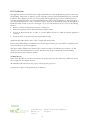
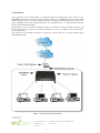
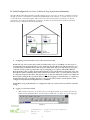
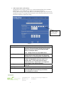
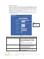
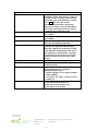
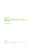
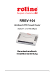
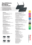
4 PORT ROUTER/SWITCH (P/N 364732-01) OWNER’S MANUAL 1307742 REV.O Innovations in Home Living. 301 Fulling Mill Road, Suite G ©Copyright 2004 by OnQ Technologies, Inc All Rights Reserved. Middletown, PA 17057 www.onqhome.com (800)-321-2343 i FCC Certifications This equipment has been tested and found to comply with the limits for a Class B digital device, pursuant to Part 15 of the FCC Rules. These limits are designed to provide reasonable protection against harmful interference in a residential installation. This equipment generates, uses and can radiate radio frequency energy and, if not installed and used in accordance with the instructions, may cause harmful interference to radio or TV communications. If this equipment does cause harmful interference to radio or television reception, which can be determined by turning the On-Q Home 4 Port Router/Switch off and on, the user is encouraged to try to correct the interference by one or more of the following measures: • Reorient or relocate the affected receiving radio or TV antenna. • Increase the separation between the Router/Switch and affected device. • Connect the Router/Switch into an outlet on a circuit different from that to which the affected equipment is connected. • Consult the dealer or an experienced radio/TV technician for help. Shielded interface cables must be used in order to comply with emission limits. You are cautioned that changes or modifications not expressly approved by the party responsible for compliance could void your authority to operate the equipment. This device complies with Part 15 of the FCC rules. Operation is subject to the following two conditions: (1) This device may not cause harmful interference, and (2) This device must accept any interference received, including interference that may cause undesired operation. CE Mark Warning This is a Class B product. In a domestic environment, this product may cause radio interference, in which case the user may be required to take adequate measures. All trademarks and brand names are the property of their respective proprietors. Specifications are subject to change without prior notification. Innovations in Home Living. 301 Fulling Mill Road, Suite G ©Copyright 2004 by OnQ Technologies, Inc All Rights Reserved. Middletown, PA 17057 www.onqhome.com (800)-321-2343 ii TABLE OF CONTENTS I. Introduction 1 II. Product Overview 2 A. B. C. D. Features Components Included Replacement Parts Detailed Physical Description 2 2 2 3 III. Installation 4 A. “Rough-In” Steps B. “Trim-Out” Steps 4 4 IV. Initial Configuration 5 A. Configuring a Network Interface Card to talk to the Router/Switch B. Logging on to the Router/Switch C. Internet Port Setup 1. Cable Modem Setup 2. DSL Setup 3. Static Route Setup D. Local Port Setup V. Advanced Setup 14 A. B. C. D. E. F. Management Virtual Server Packet Filter Static Route Dynamic DNS Network Status 1. Connection Status 2. Sessions List 3. Users List G. Others 1. Factory Reset 2. Saving Configuration 3. Firmware Upgrade 14 16 18 20 22 23 23 24 25 26 26 27 28 VI. Troubleshooting 29 A. Contact Information B. FAQs 29 29 Appendices A. Specifications B. Supported Internet Applications C. Internet Port Link Status Innovations in Home Living. 5 5 6 7 8 10 12 33 33 34 301 Fulling Mill Road, Suite G ©Copyright 2004 by OnQ Technologies, Inc All Rights Reserved. Middletown, PA 17057 www.onqhome.com (800)-321-2343 iii I. Introduction The On-Q Home 4 Port Router/Switch is an integrated Internet IP sharing device with a built-in 4-port 10/100Mbps Fast Ethernet switch. Its superb throughput as high as up to 80Mbps between Internet and LAN makes it the perfect solution to connect a small group of PCs to a high-speed broadband Internet connection (see Figure 1). Multiple users can have high-speed Internet access simultaneously via one single IP address (Internet account) of the Cable/xDSL modem. This product also serves as an Internet firewall, protecting your network from being accessed by outside users. All incoming data packets are monitored and filtered. The Router can also be configured to filter internal users’ access to the Internet. The built-in 4-port Fast Ethernet Switch lets users plug the network cable into the device without buying additional Hub/Switch. Page iv Figure 1: Small Office/ Home Office Setup Innovations in Home Living. 301 Fulling Mill Road, Suite G ©Copyright 2004 by OnQ Technologies, Inc All Rights Reserved. Middletown, PA 17057 www.onqhome.com (800)-321-2343 1 II. Product Overview A. Features • Superb performance with throughput as high as up to 80Mbps between Internet and LAN. • Supports PPPoE. • Supports VPN. (PPTP, IP- Sec pass thru) • Supports Auto MDI/MDIX for both LAN/Internet Port. • Rich Internet applications are supported such as MSN Messenger, Yahoo Messenger StarCraft, AOE, AoM, Battle.net multi-user, Crazy Arcade, CS, E-Donkey, E-Mule, FlashGet, NetMeeting, ICQ, mIRC, Web browser, FTP, Telnet, E-Mail, News, Ping, PCAnyWhere... • DHCP server allocates up to 253 client IP addresses. • Allows up to 32 Static DHCP connections. • Proxy DNS supported. • Dynamic DNS (DDNS) supported. • Up to 24 Virtual Servers supported. • DMZ host & Multi-DMZ supported. • Up to 24 Packet Filters supported. • Static routing supported. • Firmware upgrades through the network supported. • Supports Windows 95/98/ME/NT/2000/XP, Unix, and Mac. • Natural firewall keeps hackers out. • Load/Save device settings from/to a PC file. B. Components Included The On-Q Home 4 Port Router/Switch includes the following parts: • Router/Switch Module • Router/Switch 9VDC Power Supply • Router/Switch Manual on CD • Router/Switch User Guide C. Replacement Parts Replacement parts available for the On-Q Home 4 Port Router/Switch include: • Router/Switch 9VDC Power Supply (P/N 364723-01) Innovations in Home Living. 301 Fulling Mill Road, Suite G ©Copyright 2004 by OnQ Technologies, Inc All Rights Reserved. Middletown, PA 17057 www.onqhome.com (800)-321-2343 2 D. On-Q Home 4 Port Router/Switch Detailed Physical Description The following information describes the physical characteristics of the On-Q Home Router/Switch: 1. Router/Switch Module Connection Area Figure 2 shows the Router/Switch connection area including: 9 VDC Power Receptacle – connection from power supply WAN (Network) Port – 8 position RJ-45 jack (connects to Cable or DSL modem) Local Switch Ports – 8 position RJ-45 jacks (connection from outlets in rooms) Reset Button - A dual-function button. A brief button press (with a pencil, pen, or other pointed object) resets the Router/Switch unit, while a longer button press (over 5 seconds) resets the Router/Switch unit to the factory default settings. If the Router/Switch is experiencing trouble connecting to the Internet, briefly press and release the Reset button to reset the unit. The Router/Switch will retain its configuration information during this reset operation. To reset the unit to the factory defaults, while the unit is powered, press and hold the Reset button for more than 5 seconds. This clears the user settings, including User ID, Password, IP Address, and Subnet Mask. NOTE: Refer to Section IV Configuration for instructions on re-configuring the Router/Switch. Switch Port LEDs WAN LED Status LED Power LED STATUS 9 VDC Input Network Port Local Switch Ports Reset Button Figure 2 2. Router/Switch Status LEDs (see Figure 2) Power – On solid green when power is supplied. Status LED – On solid red indicates device is not working properly. Blinks red during power-up. WAN (Network) LED – On solid green to indicate connected and linked to a Cable or DSL Modem. Blinks green to indicate receiving or sending data over the network. Local Switch Port LEDs– On solid green to indicate proper connection to a local device (PC Network Interface Card). Blink to indicate receiving or sending data. Innovations in Home Living. 301 Fulling Mill Road, Suite G ©Copyright 2004 by OnQ Technologies, Inc All Rights Reserved. Middletown, PA 17057 www.onqhome.com (800)-321-2343 3 III. Installation The On-Q Home 4 Port Router/Switch is best installed during new construction in two steps; at “rough-in” after the Electricians are done, but prior to drywall being installed, and at “trim-out” after the drywall is installed and painted. These steps are detailed below: A. “Rough-in” steps: 1. A single CAT5e should be run in the walls from the structured wiring enclosure location in the home where the On-Q Home 4 Port Router/Switch will be installed to each outlet location in the rooms where Internet service is required (leave extra cable at both ends). 2. At the selected outlet locations, a single gang box or mud ring should be installed, with the extra CAT5e cable in the box, or attached in such a way that it may be fished out after the drywall is installed. B. “Trim-out” steps: 3. The CAT5e that was secured at each of the outlets should be pulled out and terminated with a punchdown tool on an RJ45 insert and attached to a wallplate, which is then installed in the single gang box or mud ring. 4. In the structured wiring enclosure the CAT5e from the outlets may be terminated with a punchdown tool onto an On-Q Home 5 Port Network Interface Module’s RJ45 Inserts or with RJ45 plugs for direct connection to the On-Q Home 4 Port Router/Switch. 5. The On-Q Home 4 Port 10/100 Router/Switch is installed in the structured wiring enclosure by slipping the tabs into the square holes, and using the push pin in a round hole to secure the router. 6. If the outlet cables were punched down at a Network Interface Module, CAT5e patch cables are then connected from the On-Q Home 5 Port Network Interface Module to the input ports on the OnQ 4-Port 10/100 Router/Switch. 7. An additional CAT5e patch cable is then connected from the network (WAN) port of the 4 Port 10/100 Router/Switch to the Cable Modem or DSL Modem housed in the structured wiring enclosure. 8. The 4 Port 10/100 Router/Switch is powered with an AC to DC adapter which also needs to be plugged in to an AC source. 9. Follow the steps in the next two sections for configuring the router. NOTE: Use proper tools and standard TIA 568A rules to prep and terminate the CAT5e cable, such as the On-Q Home CAT5 Cable Stripper (P/N 363292-01) and the On-Q Home EZ RJ45 Crimp Tool (P/N 364555-01). Innovations in Home Living. 301 Fulling Mill Road, Suite G ©Copyright 2004 by OnQ Technologies, Inc All Rights Reserved. Middletown, PA 17057 www.onqhome.com (800)-321-2343 4 IV. Initial Configuration (see Section V Advanced Setup Steps for more information) The On-Q Home 4 Port Router/Switch is typically configured in one of two ways; (1) From a portable PC connected through one of the Local Switch Ports on the Router/Switch Module in the enclosure, or (2) From a PC in one of the rooms of the house, connected through an outlet in the room to the enclosure where it is patched to (or directly connected to) one of the Local Switch Ports (see Figure 3). In either case, the PC must have an Ethernet Network Interface Card to communicate with the Router/Switch. Figure 3 A. Configuring a Network Interface Card to talk to the Router/Switch NOTE: The steps below assume that your PC’s network interface card is set to DHCP, or in other words, to obtain IP addressing automatically. The steps also assume that the On-Q Home 4 Port Router/Switch is set to its default setting of “Distribute IP” for the local ports and that all the cables previously discussed are properly connected. It is also possible to perform these steps by configuring your computer (with installed Ethernet Network Interface Card) to talk to the On-Q Router/Switch on its specific IP subnetwork (192.168.1.xxx). The On-Q Router/Switch’s default IP address in that subnetwork is 192.168.1.254, so your PC’s Ethernet Card can be temporarily assigned an IP address, (like 192.168.1.10), on that same subnetwork to talk to and configure the Router/Switch. Giving the PC a specific IP address is also called assigning it a Static IP address, as compared to a Dynamic IP address that is typically assigned by a service provider when your PC’s network interface card is configured for Dynamic Host Configuration Protocol (DHCP). NOTE: Before doing any PC IP Address re-configuration, make sure you first write down all of the current IP settings. B. Logging on to the Router/Switch 1. With your PC connected to one of the local ports on the Router/Switch, open a browser and enter the Router/Switch’s default IP address (192.168.1.254), and click “Go” (see Figure 4) to get the login page. Figure 4 Innovations in Home Living. 301 Fulling Mill Road, Suite G ©Copyright 2004 by OnQ Technologies, Inc All Rights Reserved. Middletown, PA 17057 www.onqhome.com (800)-321-2343 5 NOTE: No user name is required and the default password is left blank. 2. To logon, just click OK (see Figure 5). Figure 5 NOTE: At the setup home page, the tabs at the top of the page are provided to link you directly to the desired setup screen. You can select Internet Port, Local Port, Advanced Setup (Management, Virtual Server, Packet Filter, Static Route, Dynamic DNS), Network Status (Connection Status, Sessions List, Users List) and Others (Factory Reset, Save Configuration, Firmware Upgrade). C. Internet Port Setup This screen (see Figure 6) contains settings for the Internet (WAN) connection interface to your service provider. Click on the down arrow to select your specific Internet connection mode on the list (configure only one). Figure 6 Obtain configuration automatically (CATV dynamic mode) PPPoE (DSL dynamic mode) For users who are using Cable Modem Internet service. For users who are using xDSL Internet service that runs PPPoE. If your xDSL service uses PPPoE, after installing the IP Sharing device, do not run PPPoE software on your computers. Select this item when the ISP assigns static IP address for your account. Static configuration Innovations in Home Living. 301 Fulling Mill Road, Suite G ©Copyright 2004 by OnQ Technologies, Inc All Rights Reserved. Middletown, PA 17057 www.onqhome.com (800)-321-2343 6 1. CATV dynamic Mode (Cable Modem) Selecting this mode (see Figure 7) enables you to obtain dynamic IP address from your ISP via DHCP support. Once the IP address is obtained, you can access the Internet. For most cases, this page needs no input. However, some ISPs may require some information for identification purpose. For example: Device/Computer name and Domain Name; please enter the information required to complete the settings. Check to modify the MAC address when necessary. Figure 7 Device Information Adapter Address Device/Computer Name Domain Name IP Config DNS Configuration DNS Server Innovations in Home Living. This field is grayed out, because the Adapter Address is not supposed to be entered randomly. Do Not alter the contents unless you are sure it is necessary to modify your MAC address. To modify the address; check Modify and enter the desired MAC address. Enter a descriptive name for identification purpose. Some Internet Service Providers (ISP) requires this information, and if that is the case, they will provide you with the name. For example: yourcompany.com. The maximum input for this field is 32 alphanumeric characters and it is case insensitive. Note: 1. Your ISP may ask you to input a certain domain name. 2. Domain name is also required for internal network’s email and news functions. This field is grayed out for the IP address is obtained dynamically Select Dynamic or Static. Enter the information of Primary and Secondary DNS Server provided by your ISP when Static configuration is selected. 301 Fulling Mill Road, Suite G ©Copyright 2004 by OnQ Technologies, Inc All Rights Reserved. Middletown, PA 17057 www.onqhome.com (800)-321-2343 7 2. PPPoE (DSL dynamic Mode) If this mode is selected (see Figure 8) and settings are saved, this Router/Switch will be connected to the Internet over an always-on connection by a method provided by PPPoE. PPPoE offers simulated dial-up software like Microsoft Dial-Up Networking, which saves users’ time and effort to run the program on their PCs. And the auto-connect/disconnect feature lets the system stay in an idle state when there is no activity, but pick up the connection quickly when there is network activity. This can significantly save users’ cost on connection fees. The MTU function lets you choose the maximum packet size that fits your need for optimal throughput. Reducing the packet size can help with connecting to certain web sites or with speeding up packet transfer and reception. Check to modify the MAC address when necessary. Figure 8 Device Information Adapter Address This field is grayed out, because the Adapter Address is not supposed to be entered randomly. Do Not alter the content unless you are sure it is necessary to modify your MAC address. To modify the address, check Modify and enter the desired MAC address. Enter a descriptive name for identification purpose. Some Internet Service Providers (ISPs) requires this information, and if that is the case, they will provide you with the name. For example: yourcompany.com. The maximum input for this field is 32 alphanumeric characters and it is case insensitive Device/Computer Name Domain Name Innovations in Home Living. 301 Fulling Mill Road, Suite G ©Copyright 2004 by OnQ Technologies, Inc All Rights Reserved. Middletown, PA 17057 www.onqhome.com (800)-321-2343 8 PPPoE Information PPPoE Account Username Password Service Name Max packet size (MTU) Static IP Address: Static DNS Server Auto-disconnect if idle for minutes Auto-reconnect Innovations in Home Living. Active Profile ~1 ~2 ~3 You can set up to three PPPoE accounts, while only one account can be enabled at a time. To set the profile, select the profile number, enter all the information, and then click on Save. The device will save the information, restart and return to the previous menu page. If you don’t see the saved information on the screen, from the menu on the left, click on the “Internet Port” to refresh the screen. Maximum input is 52 alphanumeric characters (case sensitive) Maximum input is 36 alphanumeric characters (case sensitive) For identification purpose. If it is required, your ISP will provide you with the information. Max packet size (MTU): Click the down arrow to select the most appropriate MTU (maximum transfer unit, segment size; default value is 1452) for your application. Reducing the packet size can help connecting to certain web sites or speeding up packet transfer rate. If the incorrect selection is selected, you may not be able to open certain web sites. Enter the IP address provided by your ISP. Enter the primary and secondary DNS addresses provided by your ISP. Configure this device to disconnect the PPPoE connection when there is no activity for a predetermined period of time. • Default: 5 minutes. You can input any number from 0 to 65535. • To keep the line always connected, set the number to 0. Check to enable auto-reconnected with PPPoE line. This function allows the device to automatically reconnect when the line is disconnected due to ISP problem. 301 Fulling Mill Road, Suite G ©Copyright 2004 by OnQ Technologies, Inc All Rights Reserved. Middletown, PA 17057 www.onqhome.com (800)-321-2343 9 3. Static Mode For leased line users, information provided by their ISP has to be filled in the below respective fields when this mode is selected (see Figure 9). Information from your ISP includes: IP address, Subnet Mask, Gateway, primary DNS and secondary DNS. NOTE: There may be more than one IP address assigned by your ISP, select one address and enter its associated information in the corresponding fields. Figure 9 Device Information Adapter Address This field is grayed out, because the Adapter Address is not supposed to be entered randomly. Do Not alter the content unless you are sure it is necessary to modify your MAC address. To modify the address, check Modify and enter the desired MAC address. Enter a descriptive name for identification purpose. Some Internet Service Providers (ISP) requires this information and if that is the case, they will provide you with the name For example: yourcompany.com. The maximum input for this field is 32 alphanumeric characters and it is case insensitive Device/Computer Name Domain Name Innovations in Home Living. 301 Fulling Mill Road, Suite G ©Copyright 2004 by OnQ Technologies, Inc All Rights Reserved. Middletown, PA 17057 www.onqhome.com (800)-321-2343 10 IP Address IP Address Subnet Mask Gateway DNS Server Configuration Primary/Secondary Enter the information provided by your ISP. Enter the information provided by your ISP. Enter the information provided by your ISP. Enter the information provided by your ISP. SAVE After completing the settings on this page, click SAVE to save the settings. Click UNDO to clear all the settings on this page. UNDO Innovations in Home Living. 301 Fulling Mill Road, Suite G ©Copyright 2004 by OnQ Technologies, Inc All Rights Reserved. Middletown, PA 17057 www.onqhome.com (800)-321-2343 11 D. Local Port Setup This screen (see Figure 10) contains settings for configuring the LAN (4-port switch) side of the product, where your PCs are connected. You can set to distribute IP address to local PCs or not. If “Distribute IP address to local computer” is selected, users can enter the starting IP address for the group of attached PCs. The number of IP address decides the total number of clients allowed. NOTE: All the PCs on the same LAN (switch) should use the same subnet Mask. Users can also set Static DHCP in this page. Users are allowed to set 32 Static DHCP. Using this feature, the device will assign the same IP address to a computer (according to the network adapter’s MAC address) and this computer becomes the only one able to request that IP address. This is useful for support of virtual servers which require fixed IP addresses for outside Internet access. Figure 10 Private Network IP Address Subnet mask DHCP Server Do not distribute IP address to local computers Distribute IP addresses to local computers Start IP address Innovations in Home Living. Default: 192.168.1.254 (this is the local address of this On-Q Router/Switch) Default: 255.255.255.0 Check this radio button to disable this device from distributing IP Addresses (DHCP Server disabled) Check this radio button to enable this device to distribute IP Addresses (DHCP enabled). This enables the following field for you to enter the starting IP Address The starting IP address of this local IP network address pool. The pool is a piece of contiguous IP addresses. The default value (192.168.1.1) should work in most cases. 301 Fulling Mill Road, Suite G ©Copyright 2004 by OnQ Technologies, Inc All Rights Reserved. Middletown, PA 17057 www.onqhome.com (800)-321-2343 12 • Number of IP address Maximum: 253. Default value should work in most cases. Note: If “Continuous IP address poll starts” is set at 192.168.1.1 and the “Number of IP address in pool” is 253, the device will distribute IP addresses from 192.168.1.1 to 192.168.1.253 to all the computers in the network that request IP addresses from DHCP server. Click the ADD button to enter the Static DHCP page. Enter IP and Network adapter MAC addresses for Static DHCP and click the ADD button to save the settings. Click DELETE ALL to clear all entries. Click the Index drop-down menu to select the desired entry number and then click DELETE to delete only the selected server. You can add up to 32 static DHCP IP addresses. Click BACK to return to the Local Port page to continue Static DHCP IP&MAC addr. If you clicked on the Static DHCP & MAC addr. "config.” Button, this screen (see Figure 11) allows you to configure and add up to 32 Static DHCP addresses. Figure 11 WINS server When necessary, enter the IP Address of the Windows domain name server. SAVE After completing the settings on this page, click SAVE to save the settings. Click UNDO to clear all the settings on this page. UNDO Innovations in Home Living. 301 Fulling Mill Road, Suite G ©Copyright 2004 by OnQ Technologies, Inc All Rights Reserved. Middletown, PA 17057 www.onqhome.com (800)-321-2343 13 V. Advanced Setup A. Management On this management screen (see Figure 12), you can 1. Change Administrator’s password: change the password for the device. 2. Limit Management: Enables two stations to manage this Router/Switch through Web configuration. Enter the MAC addresses of the stations you selected for management. After the setup is completed, only the assigned stations with correct password authentication can manage this device. 3. Block Internet Request: Blocks requests from Internet to the local network. If this item is checked, the function of management through Web configuration will be disabled. In other words, Internet requests and the HTTP management, namely ICMP, IDENT, and HTTP will be rejected. Management via Internet: Allows management of this device via HTTP from Internet. 4. Modify the Configuration Port. Figure 12 Change Administrator’s password New Password Enter the new password. Confirm New Re-enter the new password for confirmation. Password Innovations in Home Living. 301 Fulling Mill Road, Suite G ©Copyright 2004 by OnQ Technologies, Inc All Rights Reserved. Middletown, PA 17057 www.onqhome.com (800)-321-2343 14 Limit Management Station Click to enable this function. Section 1 MAC Enter the first management station’s network adapter MAC addresss. Address Section 2 MAC Enter the second management station’s network adapter MAC address. If Address you are only setting up one management station, leave Station 2 MAC address with all F’s. Block Internet Request Click to enable this function. Management via This field will be automatically disabled when Block Internet Request is Internet checked. If Block Internet Request is not enabled, you can choose to enable/disable this function. Below are the results of checking or not checking the Block Internet Request and HTTP management for this device. (V: Checked and O: Unchecked) Block Internet Request V Management Via Internet O (automatically) O V O O Modify the configuration port Web Configuration port Non-standard FTP port number FTP Port Number Result WAN requests over TCP 113 (IDENT) and ICMP are rejected. HTTP management is not allowed. WAN requests over TCP 113 (IDENT) and ICMP are accepted. HTTP management is allowed. WAN requests over TCP 113 (IDENT) and ICMP are accepted. HTTP managements is not allowed. Enable Enable Input the port number for web configuration. The default web port for configuration is set to 80. If you want to set the port to another port, input that port number and click SAVE. Once the web configuration port is modifiied, configuation over web should be checked with the new setting; e.g. if the web configuration port was set to 8080, to login the web configuration, you need to input the address like: http://192.168.1.254:8080 (where 192.168.1.254 is your local port IP address.) Check to modify the standard FTP port number. Enter the new FTP port number (default is 21). SAVE After changing the setting(s), click SAVE to save the setting(s) Click UNDO to clear all the settings on this page. UNDO Innovations in Home Living. Check to modify web configuration port number settings. 301 Fulling Mill Road, Suite G ©Copyright 2004 by OnQ Technologies, Inc All Rights Reserved. Middletown, PA 17057 www.onqhome.com (800)-321-2343 15 B. Virtual Server On this Virtual Server screen (see Figure 13), you can set up a local server with specific port number that stands for the service (e.g. web(80), FTP(21), Telnet(23)). When this device receives an incoming access request for this specific port, it will be forwarded to the corresponding internal server. You can add virtual servers by either port numbers or by names. There are a maximum of 24 Server entries allowed and each port number can only be assigned to one IP address. NOTE: Setting up a Virtual Server is like opening the firewall, which exposes your network to users on the Internet. Which means the Router’s NAT will no longer be able to provide protection from hackers. Figure 13 Innovations in Home Living. 301 Fulling Mill Road, Suite G ©Copyright 2004 by OnQ Technologies, Inc All Rights Reserved. Middletown, PA 17057 www.onqhome.com (800)-321-2343 16 Add Virtual Server Method ~By Name ~ By Port Application (Port) Port Type Single/Range, Port Number Local Server IP Address You can select to set up a virtual server either by name or by port number. Click to scroll down. Select from the most popular server applications for Virtual Server. Select the port type (TCP or UDP) for the port number that was entered earlier. Select a specific port or a range of ports which you want the Internet users to be able to access. The valid port number ranges from 0 to 65535. Enter the Local Server’s IP address (for the specified port entered above). UNDO ADD Click UNDO to clear all the settings on this page. Each time you finished setting, click ADD and the added servers will appear on the Server List. Server List DELETE ALL DELETE Display of all the virtual servers. Click to delete all the servers on the list. Click the Index drop-down menu to select the desired server number and then click DELETE to delete only the selected server. DMZ Host Function: If the DMZ Host Function is enabled, it means that you set up a DMZ host at a particular computer to be exposed to the Internet so that some applications/software, especially Internet / online game can have two-way connections. You can enter up to four DMZ Hosts. Enter the WAN IP Address set for DMZ Host. Enter the local IP address mapping to the client computer, which you want to use as the DMZ Host computer. DMZ WAN IP Address DMZ LAN IP Address UNDO ADD Click to clear all the settings on this page. After completing the settings on this page, click “ADD” to save the settings. DMZ List Display all the DMZ hosts. DELETE ALL DELETE Click to delete all the DMZ host(s) on the list. Click on the Index drop-down menu to select the desired host number and then click DELETE to delete only the selected host. Innovations in Home Living. 301 Fulling Mill Road, Suite G ©Copyright 2004 by OnQ Technologies, Inc All Rights Reserved. Middletown, PA 17057 www.onqhome.com (800)-321-2343 17 C. Packet Filter The Packet Filters screen (see Figure 14) allows you to block specific users from accessing the Internet and you can also disable specific Internet services. There are three different types of filters that may be applied (MAC Address of the network interface card, IP Address single or range, or TCP/UDP Port). Each filter can be set to filter (drop) or forward (pass) packets. You can program up to 24 total filters. Figure 14 Network Adapter Address Filter IP Address Filter Single/Range IP Range Direction ~From Local IP ~To Remote IP Innovations in Home Living. Filter (block) or forward (pass) info from/to local computer’s network adapter MAC address (also known as the adapter card’s Physical Address). Filter/forward using computer’s IP address. You can filter/forward a single IP, or a range of the IP addresses. Enter the Start and End IP addresses for a range of IP addresses to filter/forward. Filtering IP address of a local computer; or filtering IP address of a remote server (this remote server connects to the device via Internet). 301 Fulling Mill Road, Suite G ©Copyright 2004 by OnQ Technologies, Inc All Rights Reserved. Middletown, PA 17057 www.onqhome.com (800)-321-2343 18 TCP/UDP Port Filter Filter using the port number. You can set filter for a single port or a range of ports. NOTE: Performing a Factory Reset will erase all previously entered device settings. Filter/Forward Select to Filter or Forward for the following assigned port(s). You can filter a single port, or a range of ports The port number(s) for the filters. TCP port: filter according to the ConnectionBased Application Service on the remote server using the port number. UDP port: filter according to the Connectionless Application Service on the remote server using the port number. Single/Range Port Number Port Type ADD Each time you finish setting a filter, click the ADD button and the added filter will appear on the Filter List Click UNDO to clear all the settings in this categrory UNDO Filter List DELETE ALL DELETE Innovations in Home Living. Displays all the Packet Filters. Click to delete all the filters on the list. Click on the Index drop-down menu to select the desired filter number and then click DELETE to delete only the selected filter. 301 Fulling Mill Road, Suite G ©Copyright 2004 by OnQ Technologies, Inc All Rights Reserved. Middletown, PA 17057 www.onqhome.com (800)-321-2343 19 D. Static Route You can create static routes (see Figure 15) to manually administrate the network topology/traffic when the dynamic route is not effective enough. As mentioned before, static routes may be required by the ISP if you utilize a leased line for network access or for use with virtual servers. To create static routes, select “Static Route #1” or “Static Route #2”, and enter the appropriate destination network/host settings. When finished, click “SAVE” to save settings. Click “UNDO” to clear all entries. Figure 15 As discussed before, you may be required by the ISP to link a particular PC or server’s network interface card to a provided service (see Figure 16). Enter the appropriate information as directed by the ISP. Figure 16 Innovations in Home Living. 301 Fulling Mill Road, Suite G ©Copyright 2004 by OnQ Technologies, Inc All Rights Reserved. Middletown, PA 17057 www.onqhome.com (800)-321-2343 20 Device Information Adapter Address This field is grayed out, because the Adapter Address is not supposed to be entered randomly. Do Not alter the content unless you are sure it is necessary to modify your MAC address. To modify the address, check Modify and enter the desired MAC address. Enter a descriptive name for identification purpose. Some Internet Service Providers (ISP) requires this information and if that is the case, they will provide you with the name For example: yourcompany.com. The maximum input for this field is 32 alphanumeric characters and it is case insensitive Device/Computer Name Domain Name IP Address IP Address Subnet Mask Gateway DNS Server Configuration Primary/Secondary Enter the information provided by your ISP. Enter the information provided by your ISP. Enter the information provided by your ISP. Enter the information provided by your ISP. SAVE After completing the settings on this page, click SAVE to save the settings. Click UNDO to clear all the settings on this page. UNDO Innovations in Home Living. 301 Fulling Mill Road, Suite G ©Copyright 2004 by OnQ Technologies, Inc All Rights Reserved. Middletown, PA 17057 www.onqhome.com (800)-321-2343 21 E. Dynamic DNS The Dynamic DNS screen (see Figure 17) allows you to alias a dynamic IP address to a static hostname, allowing your device to be more easily accessed by specific name. When this function is enabled, the IP address in Dynamic DNS Server will be automatically updated with the new IP address provided by ISP (this function requires Dynamic DNS Service). Figure 17 Dynamic DNS Enable Click to enable this function and make the settings available. ? Click on the question mark to find out more about Dynamic DNS Service. Note: If you don’t already have the Dynamic DNS Service, please click on the ? and then follow the instructions to sign up for the service. Enter your host domain name. Click the down arrow to select your Dynamic DNS client with which you registered for the service. Enter your user name, which was registered with the Dynamic DNS client. Enter your password, which was registered with the Dynamic DNS client. Check to enable the Wildcard function. To know more about Wildcard, please refer to FAQ section. To know more about MX (Mail Exchanger), please refer to FAQ section. Check to have Backup MX service enabled. DNS Account User Name Password Enable Wildcard Mail Exchanger Backup MX? Status Displays the results of the action. If action failed, click Refresh to enable the function. UNDO SAVE Click to clear all the settings on this page. After completing the settings on this page, click SAVE to save the settings. Innovations in Home Living. 301 Fulling Mill Road, Suite G ©Copyright 2004 by OnQ Technologies, Inc All Rights Reserved. Middletown, PA 17057 www.onqhome.com (800)-321-2343 22 F. Network Status 1. Connection Status This screen (see Figure 18) displays the current Internet connection status. After the device is connected to the Internet Service, you will see IP, Subnet Mask, Gateway and DNS IP addresses on the table. Figure 18 RELEASE/DISCONNECT RENEW/CONNECT Innovations in Home Living. Click on this button to disconnect from ISP and release all the IP information on the Internet Port. Click on this button to reconnect to the ISP and renew all IP information on the Internet Port. 301 Fulling Mill Road, Suite G ©Copyright 2004 by OnQ Technologies, Inc All Rights Reserved. Middletown, PA 17057 www.onqhome.com (800)-321-2343 23 2. Sessions List This screen (see Figure 19) displays active Internet sessions through this device. Figure 19 REFRESH Click on this button to refresh the list and get the latest session list. Displays TCP or UDP port type. The local network IP address/port number of one end point of the session. An NAT feature where a Port Fake is used to translate the local network IP address for connecting to the Internet. The outside network IP address/port number of the other end of the session. The idle time of the session. If the idle time is too long (more than 15 minutes), the device will disconnect the idled session. T/U IP Client/ Port Client Port Fake IP Remote/Port Remote Idle Innovations in Home Living. 301 Fulling Mill Road, Suite G ©Copyright 2004 by OnQ Technologies, Inc All Rights Reserved. Middletown, PA 17057 www.onqhome.com (800)-321-2343 24 3. Users List This screen (see Figure 20) displays the current active users. Figure 20 REFRESH Click this button to refresh the list. Innovations in Home Living. 301 Fulling Mill Road, Suite G ©Copyright 2004 by OnQ Technologies, Inc All Rights Reserved. Middletown, PA 17057 www.onqhome.com (800)-321-2343 25 G. Others 1. Factory Reset (see Figure 21) To reset to factory default settings, click the GO button. NOTE: Performing the Factory Reset will erase all previously entered device settings. Figure 21 Innovations in Home Living. 301 Fulling Mill Road, Suite G ©Copyright 2004 by OnQ Technologies, Inc All Rights Reserved. Middletown, PA 17057 www.onqhome.com (800)-321-2343 26 2. Save Configuration This function (see Figure 22) enables users to always save the current configurations as a file (i.e. config.sav), so that no re-entry is required when users want to switch between various configurations. To load a configuration from a file, enter the file name or click Browse… to find the file from your computer. Figure 22 Figure 23 SAVE UNDO LOAD Figure 24 Click SAVE to save the current configuration to file. Click to clear the input. Click to start loading configuration from file when you are done with the previous settings. When prompted (see Figure 23), select “Save this file to disk”, and the Save As screen (see Figure 24) will prompt you with a dialog box to enter the file name and the file location. Please note that the configuration file is in a .sav format. Load Configuration From File File Path/Name If you want to load a configuration file, enter the file name with the correct path and then click on LOAD. Or click Browse… to select the file. Innovations in Home Living. 301 Fulling Mill Road, Suite G ©Copyright 2004 by OnQ Technologies, Inc All Rights Reserved. Middletown, PA 17057 www.onqhome.com (800)-321-2343 27 3. Firmware Upgrade (see Figure 25) a. b. Download the latest firmware from your distributor and save the file on the hard drive. Make sure all computers in the network are off; or connect the Broadband Router directly to the PC that has the new firmware. c. Start the browser, open the configuration page, click on Others, and click Firmware Upgrade to enter the Firmware Upgrade window. Enter the new firmware’s path and file name (i.e. C:\FIRMWARE\firmware.bin). Or, click the Browse button, find and open the firmware file (the browser will display to correct file path). d. Click UNDO to clear all the settings on this page. Or click UPGRADE NOW to start the upgrade. Figure 25 Innovations in Home Living. 301 Fulling Mill Road, Suite G ©Copyright 2004 by OnQ Technologies, Inc All Rights Reserved. Middletown, PA 17057 www.onqhome.com (800)-321-2343 28 VI. Troubleshooting This section will detail possible solutions to common problems that might occur in using the On-Q Wireless Access Point (WAP). A. Contact Information If you are unable to locate a solution here, please access our website at www.onqhome.com for the latest information. You can also reach us at 1-800-321-2343. B. FAQs 1. When Should I modify the MAC address for Internet port settings? Some ISPs identify the clients that attempt to attach to them by the accessing the client’s MAC address and ISP assigned host name. The MAC address required for Internet port settings is the Router’s MAC address which should be the one you already registered with your ISP, and there is no need for modifying it. However, if the ISP has been utilizing the your PC adapter card’s MAC address prior to obtaining this Router, you may have to modify the Router’s MAC address for Internet port settings to reflect the MAC address of the PC adapter card. 2. What is a DMZ? The DMZ (demilitarized zone), is a barrier between the Internet and a company's Intranet. It is a subnet that contains a firewall and proxy server, which can be in separate servers or in one server. The firewall connects to an external firewall on the Internet side, which may be at the ISP's location and is often called a "boundary router." The double firewall architecture adds an extra measure of security for the Intranet. 3. What is Dynamic DNS? The Dynamic Domain Name Service is an IP Registry service that provides a public central database where information such as email addresses, hostnames, IP addressess, etc. can be stored and retrieved. The Dynamic DNS service acts like old-style phone operator where other users call the operator, and ask to speak to you, and the operator, who knows your extension, will make the connection. Every time your computer comes online, it will inform the Dynamic DNS server what the current IP address is. Users who need to connect to your server, through the magic of DNS service, will be sent to the right place. Please visit HTTP://WWW.DYNDNS.ORG for more information. 4. What is Wildcard ? A wildcard alias is a method which is used to give your hostname multiple identities. If you were to register yourhost.com, everything (*).yourhost.com would be aliased to yourhost.com. This includes host names such as www.yourhost.com or ftp.yourhost.com. Once Wildcard features are enabled, your host can be reached by *.yourhost.dyndns.org. First , you need to register a dyanmic DNS account with www.dyndns.org. To use this service, you must register with the Dynamic DNS client. The Dynamic DNS Client service provider will give you a password or key. Refer to What’s Dynamic DNS ? question above for more information. 5. What’s MX (Mail Exchanger)? Internet email systems for both machines and network connections are prone to error. With MX, a chain of email hubs is built into the email architecture. If the "primary" mail host goes down, instead of queuing up the mails in an unreliable host on the Internet, they get sent to the "secondary" or "backup" mail exchanger for delivery, until the primary mail server returns to service. In technical term, such a service is called Backup Mail Exchanger. Innovations in Home Living. 301 Fulling Mill Road, Suite G ©Copyright 2004 by OnQ Technologies, Inc All Rights Reserved. Middletown, PA 17057 www.onqhome.com (800)-321-2343 29 6. What is PPPoE (PPP over Ethernet )? PPPoE is also known as a dial-up DSL service. It is designed to integrate broadband services into the current widely deployed, easy-to-use, and low-cost dial-up-access networking infrastructure. Thus, a customer can get greater access speed without changing the familiar dial operation concept. 7. How can I know if I am using PPPoE? PPPoE client software is provided by the ISP and should be installed onto your computer first. You run the program to connect to/disconnect from the Internet. User Account information (User Name and Password) is also required each time you connect to the Internet access. Note: After you have entered the PPPoE information during the device setup, and started up the device, the device will provide your ISP with the PPPoE information and login automatically. 8. What does the message “IP address conflict” mean? When you see the message box prompt for IP address conflict on any of the workstations in the network, this means two or more workstations have the same IP address. If you have setup the device as a DHCP server, run IPCONFIG /release and then run IPCONFIG /renew on the problem workstation (for Windows 98SE or ME, run the "winipcfg" utility, select the correct Network Adapter, click “release all” to release all current configuration, then click “renew all” to renew the IP information again,). If the DHCP function is disabled and static IP addresses are assigned to each workstation, please double check each workstation’s IP address for any duplicate IP addresses. 9. What does “Can not access the Internet” mean? Check the physical connectivity of the local network and broadband device. Make sure you are using the correct cables and the cables are connected to the network devices properly. Examine the LED of LAN port and the LED of the broadband signal input on the Cable Modem/xDSL Modem. If the LAN LED is off, make sure you are using the correct cables and the cables are connected to the devices properly. If the LED of the broadband signal is off, please contact your ISP. Check the status of this product. After checking the cabling and LEDs, you also have to check if you have entered the correct user name and password that your ISP provided. While checking, please note that the information is case sensitive. To check the Internet connection status, open the browser to start the Web configuration, select Network Status ÆWAN IP Status. Check if Link Status displays “Connect successfully”. If not, you may have to contact your ISP to see if their Internet service is available. Check the logical connectivity from your computer to the Internet (TCP/IP Network Diagnosis). The WINIPCFG program (for Win95, 98, and ME) or IPCONFIG program (for Windows 2000, NT, XP) is used to gather information about the TCP/IP connections that are active on your system. It cannot be used to dynamically adjust TCP/IP connections, but can be used to get the current IP address assignments. For Win 95/98/ME, from Windows, go to Start, click Run, enter WINIPCFG, and click OK. Figure 26 Innovations in Home Living. 301 Fulling Mill Road, Suite G ©Copyright 2004 by OnQ Technologies, Inc All Rights Reserved. Middletown, PA 17057 www.onqhome.com (800)-321-2343 30 Figure 27 displays the adapter address and current TCP/IP address. NOTE: At the “Ethernet Adapter Information”, select the correct Ethernet adapter that is installed in this computer. Select the correct Ethernet adapter. Figure 27: IP Configuration Click the More Info button to get the following detailed configuration information. Click here to reveal more. Figure 28: IP Configuration On the top (see Figure 28), the “Host Name” and “DNS server” are what the computer is called when it is looking for a named resource. The default gateway is the server through which the client connects to the Internet. The DHCP Server identifies the network server that assigns IP addresses to computers on the network. Innovations in Home Living. 301 Fulling Mill Road, Suite G ©Copyright 2004 by OnQ Technologies, Inc All Rights Reserved. Middletown, PA 17057 www.onqhome.com (800)-321-2343 31 If the product is working properly, the following should be apparent from this screen: 1) The Client should have an IP address within the prescribed range (default 192.168.1. #; where # is from 1 ~ 253). 2) The “DHCP” and “Default Gateway” should list the product’s local port address (the device’s IP address; default 192.168.1.254). 3) The DNS server IP addresses should match the DNS server IP addresses set in the device. For Win NT and Win2000, go to “Start”Æ”Programs”Æ”Accessories”Æ”Command Prompt” to open the Command Prompt. Type in IPCONFIG /ALL and hit “Enter” to see the adapter’s information. Type in IPCONFIG /RELEASE to release all adapters’ IP address and IPCONFIG /RENEW to renew IP addresses. For a list of the IPCONFIG commands, type in IPCONFIG /?. The PING.EXE command is used to verify that a computer is active and available. Users can ping a specific destination domain name or just the IP address. For example, to find the server 168.95.192.1, type the following command at the MS-DOS prompt and then press “Enter”: C:\>ping 168.95.192.1 PING can be executed in Windows as shown below: 1. Go to the Start menu. 2. Click Run. 3. Type ping 168.95.192.1 and click OK. 4. The server (IP address) is online if the following message appears. Reply from 192.168.0.1: bytes=32 time=3ms TTL=100 5. The destination device is not reachable if the following message appears. Reply from 192.168.0.1: Destination host unreachable or Request timed out. To insure you are communicating with the ISP, Issue a PING command to the IP address of your ISP’s Gateway or DNS server. For example, if the DNS server address is 203.66.81.254, at C:\> prompt, enter Ping 203.66.81.254. If successful, you can reach your ISP server. If unsuccessful (Request timeout), you may have trouble connecting to your ISP, please verify that the product is properly configured to connect to your ISP. Also verify that your Cable/DSL modem and the line are functioning. To insure you have access to the Internet, PING an IP address or domain name on Internet. For example, at the command prompt enter C:\> PING 168.95.192.1 –w 5000 or C:\> PING www.yahoo.com –w 5000 If successful, you are connected to the Internet. If you can ping the ISP’s gateway, but cannot ping a specific site (e.g. www.yahoo.com) on the Internet, chances are, your ISP has an internal problem (DNS server not available). Innovations in Home Living. 301 Fulling Mill Road, Suite G ©Copyright 2004 by OnQ Technologies, Inc All Rights Reserved. Middletown, PA 17057 www.onqhome.com (800)-321-2343 32 Appendix A Specifications Standards IEEE 802.3 10Base-T Ethernet IEEE 802.3u 100Base-TX Fast Ethernet IEEE 802.3x Flow Control Ports WAN: One 10/100Mbps RJ-45 port for Cable/DSL Modem LAN: Four 10/100Mbps switched ports Cabling type UTP Category 3 or better (10Base-T) UTP Category 5 or better (100Base-TX) Protocols Supported IP, NAT, ARP, ICMP, DHCP client/server, PPPoE, PPP, PAP, CHAP, NTP, HTTP, TFTP. Management Web-Based configuration and management GUI program for Windows 98/ME/NT/2000/XP LED indicators Power Status WAN LAN (1 – 4) Input power specifications DC 9V, 700mA Physical Dimension 134x 90x 29mm3 (W x D x H) Weight 175 g Agency and Regulatory FCC part 15 Class B, CE, VCCI, BSMI Operating Temperature 0°C to 50°C Operating Humidity 0-90% non-condensing Green Red Green for 100M/10M (flashing for activity) Green for 100M/10M (flashing for activity) Appendix B Supported Internet Applications Application Settings for Outgoing Connection Setting for Incoming connection ICQ98a,99b None None ICQ2000b, ICQ2001b NetMeeting 2.1 & 3.0 AOE DMZ function enabled None DMZ function enabled 1503(tcp) 1720(tcp) 2300-2400(tcp) 2300-2400(udp) 47624(tcp) None None 7648(tcp) 7648(udp) 24032(udp) 5632(udp), 22(udp), 5631(tcp), 65301(tcp) 22555 (tcp) None 500 (udp) VDO Live MIRC Cu-Seeme PCAnywhere Iphone 5.0 MSN 4.5 IP sec Innovations in Home Living. 2300-2400(tcp) 2300-2400(udp) 47624(tcp) None None 7648(tcp) 7648(udp) 24032(udp) 5632(udp), 22(udp), 5631(tcp), 65301(tcp) 22555 (tcp) None 500 (udp) 301 Fulling Mill Road, Suite G ©Copyright 2004 by OnQ Technologies, Inc All Rights Reserved. Middletown, PA 17057 www.onqhome.com (800)-321-2343 33 Appendix C INTERNET PORT LINK STATUS PPPoE link status “PPPoE offline. Ready to connect.” "Connecting to server." "Server found." "Start PPP negotiation." "Authentication (PAP)." "Authentication (CHAP)." "Obtaining WAN IP address." "Connect successfully." "Can not find server." "Fail on LCP stage." "Authentication(PAP) failure." "Authentication(CHAP) failure." "Fail to Obtain Internet IP address." "Server dropped the connection." "Disconnect on idle." "Connection establish timeout." DHCP link status "DHCP already claimed" "DHCP under claiming" Device’s Internet Port is not connected to the ISP’s dialup server. Dialup server for connecting to the Internet is now available. Device's Internet Port is now dialing to dialup server. Device dialed to dialup server, and is negotiating with dialup server. Negotiation is ongoing. Server is verifying the dialup account with PAP method. Server is verifying the dialup account with CHAP method. Authentication is successful! Device now is obtaining IP address from the dialup server. Device dials up to server successfully. User can connect to internet now. Device cannot dial up to the dialup server. Dial-up to server failed. Configuration for network link failed. Failed in authentication; failure was caused by wrong password. Verification on the identity of the device dialup account failed. Device cannot obtain IP address from the dialup server. Dial-up to server failed. Server cut the device's internet connection. Device is disconnected to the Internet. Device has been idle longer than the idle interval and was cut off from the connection. The idle interval value was set in the field "Auto-disconnect if idle xxx Minutes". Device was re-trying to dialing-up to server and failed. Device finally gave up dialing to the server. Device obtained IP address from DHCP server. Device is trying to obtain IP address from DHCP server. Static IP assignment link status “Static assigned” Innovations in Home Living. IP address succeeds in manually setting up. 301 Fulling Mill Road, Suite G ©Copyright 2004 by OnQ Technologies, Inc All Rights Reserved. Middletown, PA 17057 www.onqhome.com (800)-321-2343 34