1
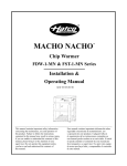
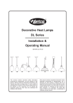
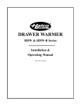
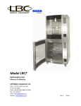
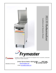
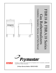
HYDRO-HEATER
Food Rethermalizers/Hot Food Table Heater
FR2 Series
Installation & Operating Manual
I&W #07.05.143.00
This manual contains important safety
information concerning the maintenance,
use and operation of this product. Failure
to follow the instructions contained in this
manual may result in serious injury. If you
are unable to understand the contents of this
manual, please bring it to the attention of your
supervisor. Do not operate this equipment
unless you have read and understood
the contents of this manual.
Este manual contiene importante información
sobre seguridad concerniente al mantenimiento,
uso y operación de este producto. Cualquier
falla en el seguimiento de las instrucciones
contenidas en este manual puede resultar
en un serio daño. Si usted no puede entender
el contenido de este manual por favor pregunte
a su supervisor. No opere este equipo al menos
que haya leído y comprendido el contenido
de este manual.
CONTENTS
Installation ............................................................5
Plumbing .........................................................5
Auto-Fill ...........................................................6
Operation ..............................................................7
Start-Up Procedures........................................7
Minutes to Heat Table .....................................8
Maintenance .........................................................9
General............................................................9
Daily ................................................................9
Weekly...........................................................10
Deliming Instructions.....................................10
Hatco Limited Warranty.....................................12
Authorized Parts Distributors ............Back Cover
Important Owner Information...............................i
Introduction ...........................................................i
Important Safety Instructions .............................1
Model Descriptions ..............................................2
All Models........................................................2
FR2 Models .....................................................2
Units with Built-In Temperature Control ..........2
Units with Remote Temperature Control .........2
Specifications .......................................................3
Electrical Rating Chart - FR2 Models .............3
Sizing Information ...........................................4
Dimensions......................................................4
Electrical..........................................................4
IMPORTANT OWNER INFORMATION
Record the model number, serial number
(identification plate located on the lower right hand
side, front corner of the unit), voltage and purchase
date of your Hydro-Heater in the spaces below.
Please have this information available when calling
Hatco for service assistance.
Business
Hours:
Model No. ________________________________
Telephone: (800) 558-0607; (414) 671-6350
(Summer Hours: June to September 8:00 a.m. to 5:00 p.m. C.D.T.
Monday through Thursday
8:00 a.m. to 2:30 p.m. C.D.T. Friday)
Fax:
Serial No. ________________________________
Voltage __________________________________
(800) 690-2966 (Parts & Service)
(414) 671-3976 (International)
24-Hour 7-Day Parts & Service
Assistance available in the
United States and Canada by
calling (800) 558-0607.
Date of Purchase __________________________
Additional information can be found by visiting our
web site at www.hatcocorp.com
INTRODUCTION
Food Rethermalizers/Hot Food Table Heaters.
We recommend all installation, operating and safety
instructions appearing in this manual be read prior
to installation or operation of your Hatco HydroHeater. Safety instructions that appear in this
and the words
manual after a warning symbol
WARNING or CAUTION printed in bold face
WARNING means there
are very important.
is the possibility of serious injury or death
CAUTION means there
to yourself or others.
is the possibility of minor or moderate injury.
CAUTION without the symbol signifies
the possibility of equipment or property
damage only.
Hatco FR2 Hydro-Heater Food Rethermalizers/Hot
Food Table Heaters are designed to supply
temperature-controlled water to a holding vessel
(sink or tank) located above the heater. Water
flows by natural convection from the holding vessel
directly into a tubular water chamber with heating
elements uniquely wrapped on the outside
of the flow tube. The heating elements do
not come in direct contact with the water
eliminating sediment and lime buildup
on the element, resulting in longer life. The heated
water flows upward and returns to the holding
vessel. A special electronic controller maintains
the setpoint temperature assuring a responsive
and efficient operation.
Hatco Hydro-Heaters are a product of extensive
research and field testing. The materials used
were selected for maximum durability, attractive
appearance and optimum performance. Every
unit is thoroughly inspected and tested prior
to shipment.
The unit electrical and plumbing connections
are factory-assembled and ready for installation.
This manual provides the installation, safety
and operating instructions for the Hydro-Heater
Form No. FR2M-0604
8:00 a.m. to 5:00 p.m.
Central Standard Time
i
IMPORTANT SAFETY INSTRUCTIONS
IMPORTANT! Read the following important safety instructions to avoid personal injury
or death, and to avoid damage to the equipment or property.
WARNINGS
CAUTIONS
Hatco FR2 series units are designed
for commercial use only by properly
trained personnel!
Water in the unit and holding vessel is very
hot. Wear protective gloves and proper attire
when operating to avoid injury.
To avoid any injury, turn the power switch
off at the fuse disconnect switch/circuit
breaker or unplug the unit from the power
source and allow to cool completely before
performing any maintenance or cleaning.
Do not use extension pipes on the inlet
and outlet connections on heater units.
Poor performance or unsafe conditions
may occur.
CAUTIONS
For proper electrical installation conforming
to local electrical codes, consult a licensed
electrical contractor.
Do not overtighten unions or nuts.
Overtightening may cause leaks.
Do not turn the electrical current to the unit
on until the holding vessel has been filled
with water or element burnout may occur.
Units are designed to heat water up to 190ºF
(88ºC). To avoid any injury or damage DO
NOT set temperature controls to a setting
higher than 190ºF (88ºC).
Inspect weekly for lime buildup inside unit.
Excessive amounts can affect unit
performance and reduce the operating life
of the unit.
For proper plumbing installation conforming
to local plumbing codes consult a licensed
plumbing contractor.
To avoid any damage to the heater unit
use only delimers that are non-corrosive
to aluminum, brass and stainless steel.
Damage caused by corrosive material
or solutions is not covered under warranty.
If service is required on this unit, contact
your Authorized Hatco Service Agent,
or contact the Hatco Service Department
at 800-558-0607 or 414-671-6350; fax
800-690-2966 or international
fax 414-671-3976.
Drain holding vessel with power to the unit
off, or element burnout may occur.
This product has no “user” serviceable
parts. To avoid damage to the unit or injury
to personnel, use only Authorized Hatco
Service Agents and Genuine Hatco Parts
when service is required.
Water Quality Requirements - Incoming
water in excess of 3.0 grains of hardness
per gallon (GPG) (.75 grains of hardness
per liter) must be treated or softened before
being supplied to a Hydro-Heater. Water
containing over 3.0 GPG (.75 GPL)
will decrease the efficiency and reduce
the operating life of the unit.
Genuine Hatco Replacement Parts
are specified to operate safely in the
environments in which they are used.
Some aftermarket or generic replacement
parts do not have the characteristics
that will allow them to operate safely
in Hatco equipment. It is essential to use
Hatco Replacement Parts when repairing
Hatco equipment. Failure to use Hatco
Replacement Parts may subject operators
of the equipment to hazardous electrical
voltage, resulting in electrical shock or burn.
1
Form No. FR2M-0604
MODEL DESCRIPTIONS
ALL MODELS
The Hydro-Heater mounts easily to the underside
of a holding vessel, leaving the entire vessel
area free. Units are shipped ready to install
with all gaskets and fittings. Hydro-Heaters include
a stainless steel front, powder coated body, a lowwater cut-off system and a convenient drain outlet.
FR2 MODELS
The Hatco FR2 model heaters are designed
to be used with a Bain-Marie or Food
Rethermalizer to heat or hold foods
at temperatures between 140ºF (60ºC) and 190ºF
(88ºC). The desired holding temperature
is maintained by a special electronic controller
and “free flow”technology.
UNITS WITH BUILT-IN TEMPERATURE
CONTROL
Units with built-in electronic temperature controller
and display are excellent for installations where
the unit is easily accessible and viewing
is not obstructed.
Figure 1. Hydro-Heater
with Built-In Temperature Controller
UNITS WITH REMOTE TEMPERATURE
CONTROL
Units supplied with remote electronic temperature
controller and display allow for easy operator
monitoring and temperature control.
Figure 2. Hydro-Heater
with Remote Electronic Controller
Form No. FR2M-0604
2
SPECIFICATIONS
ELECTRICAL RATING CHART – FR2 MODELS
Model
Voltage
Kilowatts
(kW)
Phase
Amps
Wire Sizing
Fuse or
AWG*†
Circuit Breaker* Shipping Weight
FR2-3
208
3
1
14.5
12
20
24 lbs. (11 kg)
FR2-4
208
4
1
19.2
12
30
24 lbs. (11 kg)
FR2-6
208
6
1
28.8
10
40
27 lbs. (12 kg)
FR2-3
240
3
1
12.5
12
20
24 lbs. (11 kg)
FR2-4
240
4
1
16.7
12
30
24 lbs. (11 kg)
FR2-6
240
6
1
25.0
10
40
27 lbs. (12 kg)
FR2-3B
208
3
3
8.4
14
15
24 lbs. (11 kg)
FR2-4B
208
4
3
11.2
14
15
24 lbs. (11 kg)
FR2-6B
208
6
3
16.7
12
30
27 lbs. (12 kg)
FR2-3B
240
3
3
7.3
14
15
24 lbs. (11 kg)
FR2-4B
240
4
3
9.6
14
15
24 lbs. (11 kg)
FR2-6B
240
6
3
14.5
12
20
27 lbs. (12 kg)
FR2-8
208
8
1
38.4
8
50
27 lbs. (12 kg)
FR2-8
240
8
1
33.3
8
50
27 lbs. (12 kg)
FR2-9B
208
9
3
25.0
10
40
27 lbs. (12 kg)
FR2-9B
240
9
3
21.7
10
30
27 lbs. (12 kg)
FR2-12B
208
12
3
33.4
8
50
27 lbs. (12 kg)
FR2-12B
240
12
3
29.0
10
40
27 lbs. (12 kg)
* Based upon NEC 2002 Code
† Based upon THHN wire rated 90ºC.
NOTE: NSF Standard 4 has recently added performance requirements for food rethermalizing. The requirements mirror
the requirements for food rethermalizing in the FDA Food Code. The basic requirement is that food reach a temperature
of 165°F (74°C) in a time period of two hours or less.
Appliances that are manufactured for the purpose of rethermalizing food will need to meet these performance
requirements in order to be listed to NSF Standard 4.
The Hatco FR2 Series heating unit is specifically made for food rethermalizing, however, the heating unit is designed
to be incorporated into a hot water bath rethermalizer. Hatco does not supply the vessel that contains the water,
nor the system which determines how food is placed and held in the vessel. The Hatco FR2 unit attaches to the bottom
of the vessel and supplies hot water to the vessel.
Hatco does supply sizing recommendations to enable the appliance manufacturer to correctly size the FR2 unit
to the vessel. However, there are variables in the way that the vessel is manufactured that affect its ability to pass
the NSF performance requirements. The Hatco FR2 unit is listed with NSF for construction only. Due to the fact that
the FR2 is only a portion of a larger system, it is impossible to do performance testing until the FR2 unit is incorporated
onto the water vessel.
The result is that it is the responsibility of the vessel manufacturer to have the entire rethermalizing appliance tested
and listed in accordance with NSF Standard 4. Simply hanging an NSF listed FR2 unit on the appliance does
not transfer NSF listing to the entire appliance.
3
Form No. FR2M-0604
SPECIFICATIONS
SIZING INFORMATION
ELECTRICAL
Hatco recommends the following guidelines
be used to ensure proper operation and sanitation.
Install a fused disconnect switch or circuit breaker
sized according to the applicable Electrical Rating
Chart. The wiring from the switch or circuit breaker
to the Hatco unit must be in accordance with local
electrical requirements and codes.
For FR2 Series in a Bain-Marie or Steam Table
Application
• Minimum 750 watts (.75 kW) per square foot
(0.8 watts per sq. cm) of vessel top.
WARNING
For proper electrical installation conforming
to local electrical codes, consult a licensed
electrical contractor.
For FR2 Series in a Food Rethermalizer
Application
• Minimum 2000 watts per square foot
(2.2 watts per sq. cm) of vessel top.
Models come complete with all electrical wiring
and are equipped with three electrical knockouts,
one at the rear and one on each side towards
the rear. When performing installation, run
electrical connections through one of these
knockouts.
NOTE: Use the FR2 unit for a vessel up to 6'
(1829 mm) long. Over 6' (1829 mm) minimum
two units required.
See the Minutes To Heat Table to determine
the amount of time required to heat water using
a FR2 series in a Bain-Marie or Steam Table
application.
NOTE: FR2 Series units equipped with auto-fill
have two electrical knockouts; one at the rear
and one on the right, when facing control side.
NOTE: FR2 Series units with remote electronic
controller require that the controller with 8 terminal
plug be connected to the 8 terminal receptacle
located on the front of the heater unit. Before
mounting controller, make sure it is located close
enough to the heater so the lead wires can
be properly connected.
DIMENSIONS
Width (A)
6-3/4"
(172 mm)
Depth (B)
17-1/8"
(435 mm)
Height (C)
12-3/4"
(324 mm)
B
A
C
Figure 2. Dimensions
Form No. FR2M-0604
4
INSTALLATION
PLUMBING
An adhesive backed paper template is shipped
with the unit and is used to locate the sink strainer
holes. Use the following procedure to install
the heater unit to the holding vessel.
3/4" (19 mm) holes
around periphery on
6" (152 mm) centers
3'
3'
(914 mm) (914 mm)
MAX
MAX
Dotted line
indicates the position of
perforated water baffle
3/4" (19 mm) high baffle
with divider wall between
inlet and outlet
NOTE: The FR2 heater should be positioned
with no more than 3' (914 mm) on either side
when mounted under holding vessel. See Figure 4.
A perforated water baffle (not supplied with unit)
must be used to distribute the heated
water properly.
NOTE: Use one FR2 for a Hot Food Table
up to 6' (1829 mm) long. Over 6' (1829 mm)
minimum 2 units required.
CAUTION
Do not use extension pipes on the inlet
and outlet connections on heater units. Poor
performance or unsafe conditions may occur.
Figure 4. Hydro-Heater Water Baffle
Thin rubber washer
1. Expose the adhesive back of the paper
template and stick the template on the bottom
of the holding vessel. Center the template
with the words “Front Cover” positioned against
the front inside wall of the vessel.
1/8" (3 mm)
offset
Sink or tank
3" (76 mm)
Thin fiber
washer
2. Center punch and drill a 3/4" (19 mm)
pilot hole at each of the two center marks
on the template.
Thick rubber
washers
(Qty. 2)
Nut
Union Gasket
Union nut
3. Remove the template and cut a 2" (51 mm)
diameter hole at each pilot hole location using
a standard #ATV1756 Greenlee cutter.
NOTE: If a #ATV1756 Greenlee cutter is not
available, use a standard Greenlee 1-1/2" conduit
cutter #500-6978, which is slightly under 2"
(51 mm) diameter. File or ream holes as necessary
to 2" (51 mm) diameter required for mounting
sink strainers.
Figure 5. Installing Sink Strainer
7. Tighten nuts on strainers securely.
8. Tighten union nuts securely.
9. Fill the holding vessel with water and check
for leaks.
4. See Figure 5. In each of the holes, install
a male threaded sink strainer with a thin gasket
between the strainer flange and the bottom
of the holding vessel.
CAUTION
Do not overtighten unions or nuts.
Overtightening may cause leaks.
5. Install two thick gaskets at the underside
of the holding vessel along with a thin fiber
gasket, and secure finger tight with the nut.
NOTE: A 3/4" (19 mm) hose or pipe may be connected
to the heater sump drain and run to an open sight drain.
The sump drain should not be permanently connected
to the sanitary drain system. Check local plumbing
code for proper drain installation. See
MAINTENANCE for more information.
6. Attach the heater to the strainers loosely
with the union nuts and 1-3/4" (45 mm)
rubber gaskets.
NOTE: Make sure rubber gaskets are positioned
inside the union nuts and are not crimped.
5
Form No. FR2M-0604
INSTALLATION
CAUTION
Water Quality Requirements - Incoming water
in excess of 3.0 grains of hardness per gallon
(GPG) (.75 grains of hardness per liter) must
be treated or softened before being supplied
to a Hydro-Heater. Water containing over
3.0 GPG(.75 GPL) will decrease the efficiency
and reduce the operating life of the unit.
2. Locate a point on the sidewall of the water
vessel which is 1/2" (13 mm) up from
the bottom of the food pan(s).
AUTO-FILL
5. Position upper water sensor into tank with
o-ring against inside wall.
3. Mark and drill a 1/2" (13 mm) hole into the side
wall of the tank.
4. Deburr the hole. Burrs may crack or damage
the probe when tightened.
Units with the Auto-fill option require the following
steps be completed before start-up.
6. Place washer onto threads of probe on outside
wall of tank.
WARNING
For proper plumbing installation conforming
to local plumbing codes consult a licensed
plumbing contractor.
7. Secure all with nylon nut, making sure flat side
of nut is towards washer.
8. Tighten until snug. Be careful not to overtighten
nut. Overtightening may cause leaks and/or
crack the probe.
1. Supply 1/4" NPT copper water supply line
to inlet of solenoid valve on heater.
NOTE: Ball valve or gate valve, line strainer,
union(s) and vacuum breaker or other anti-siphon
device must be supplied by table manufacturer
or installer if required.
Form No. FR2M-0604
9. Turn on water and check for leaks.
10.Connect wire lead to probe.
6
OPERATION
WARNINGS
Hatco FR2 series units are designed
for commercial use only by properly
trained personnel!
OUTLET
INLET
Power Switch
Clean-out Cap
(2- or 3-element
units only)
WARNINGS
Units are designed to heat water up to 190ºF
(88ºC). To avoid any injury or damage DO NOT
set temperature controls to a setting higher
than 190ºF (88ºC).
CAUTION
Water in the unit and holding vessel is very hot.
Wear protective gloves and proper attire when
operating to avoid injury.
Sump Drain Handle
(Closed)
Sump Drain Outlet
Figure 6. Hydro-Heater Side View
CAUTION
Do not turn the electrical current to the unit
on until the holding vessel has been filled with
water or element burnout may occur.
START-UP PROCEDURES
1. Make sure clean-out cap(s) (2-3 element units
only) are securely tightened. See Figure 6.
2. Close sump drain by moving handle all of the
way forward until it stops. See Figure 6.
3. Fill the holding vessel with hot tap water
to normal operating level.
4. Check that the fused disconnect switch
or circuit breaker is on, or if equipped
with power cord and plug make sure unit
is plugged into proper receptacle.
Figure 7. Controller
8. Press “Up” or “Down” arrow to change
and display desired setpoint.
5. Turn power switch to ON position.
The electronic display will glow to indicate
power is supplied.
9. Press “Set” button again until display goes
blank. After 5 seconds unit will display current
operating temperature.
6. To set the controller to the desired temperature
press “Set” button once; unit will display “SP1.”
See Figure 7.
NOTE: If steps 6-9 are interrupted or no changes
are made for 15 seconds the controller will
go back to its original setting without accepting
the change.
7. Press “Set” button again; unit displays
current setpoint.
7
Form No. FR2M-0604
OPERATION
MINUTES TO HEAT TABLE
Water
Temp. At
Start-Up
60°F (16°C)
9" (23 cm) DEEP WATER - 750 WATTS PER SQUARE FOOT OF VESSEL TOP
Temperature °F (°C) Water Heated To:
70
(21)
80
(27)
90
(32)
100
(38)
110
(43)
120
(49)
130
(54)
140
(60)
150
(66)
160
(71)
170
(77)
180
(82)
12
23
35
47
60
72
85
100
116
136
162
211
12
24
36
49
61
74
89
105
125
151
200
12
24
37
49
62
77
93
113
139
188
12
25
34
50
65
85
101
127
176
13
28
38
53
69
89
115
164
12
25
40
56
66
102
151
13
28
44
64
90
139
15
31
51
77
126
16
36
62
111
20
46
95
26
75
70°F (21°C)
80°F (27°C)
90°F (32°C)
100°F (38°C)
110°F (43°C)
120°F (48°C)
130°F (54°C)
140°F (60°C)
150°F (65°C)
160°F (71°C)
49
170°F (76°C)
Water
Temp. At
Start-Up
60°F (16°C)
6" (15 cm) DEEP WATER - 750 WATTS PER SQUARE FOOT OF VESSEL TOP
Temperature °F (°C) Water Heated To:
70
(21)
80
(27)
90
(32)
100
(38)
110
(43)
120
(49)
130
(54)
140
(60)
150
(66)
160
(71)
170
(77)
180
(82)
8
15
23
61
40
48
57
67
77
90
108
140
8
16
24
33
40
49
59
70
83
100
133
8
16
25
33
41
51
62
75
92
125
8
17
23
33
43
54
67
84
117
9
17
15
35
45
59
76
109
8
17
27
37
44
68
100
9
19
29
42
60
92
10
21
34
51
84
11
24
41
74
13
31
63
17
50
70°F (21°C)
80°F (27°C)
90°F (32°C)
100°F (38°C)
110°F (43°C)
120°F (48°C)
130°F (54°C)
140°F (60°C)
150°F (65°C)
160°F (71°C)
33
170°F (76°C)
Form No. FR2M-0604
8
MAINTENANCE
GENERAL
DRAINING &CLEANING ALL MODELS
WARNING
To avoid any injury, turn the power switch
off at the fuse disconnect switch/circuit breaker
or unplug the unit from the power source
and allow to cool completely before performing
any maintenance or cleaning.
NOTE: The holding vessel should be drained
through its own drain valve to discharge debris
and water that remains in it.
CAUTION
Drain holding vessel with power to the unit off,
or element burnout may occur.
Recommended Cleaning Schedule
Complete draining and cleaning should be done
DAILY (See Figure 8)
• On a daily basis.
1. Turn power switch to the OFF position.
• Whenever food particles accumulate in the tank.
2. Drain holding vessel to discharge visible water
and debris. Close drain when finished
• Whenever a spill occurs.
3. Wipe visible deposits from the sink or tank.
• Whenever the unit is to be stored or shipped,
especially in freezing temperatures.
4. Dissolve a safe, non-toxic, non-corrosive
sanitizer into 1 gallon (3.7 L) of hot water
and pour into tank. Refill the tank 1/2" (1 cm)
above the false bottom with hot water
and soak for at least 15 minutes.
Helpful Hints
• Keep inlet and outlet free of debris.
• Keep false bottoms in place and free of debris.
• Delime unit using a non-corrosive deliming
solution.
NOTE: Follow the sanitizers instructions
for the proper mixture of water and sanitizer.
CAUTION
Inspect daily for lime buildup inside unit.
Excessive amounts can affect unit performance
and reduce the operating life of the unit.
OUTLET
5. Connect one end of a drain hose onto the sump
drain outlet with the other end in a bucket
or open site drain in a manner according
to local plumbing codes.
6. To drain the unit open the sump drain valve
by moving the valve handle backwards until
it completely stops. Water will now flow from
the drain hose.
INLET
Power Switch
7. Thoroughly wash unit with fresh water until
discharge is clear and all sanitizers have been
removed and rinsed.
Clean-out Cap
(2- or 3-element
units only)
8. Close sump drain by moving handle all
of the way forward until it stops. See Figure 8.
Sump Drain Handle
(Closed)
9. Reinstall perforated water baffle/false bottom
in correct position.
Sump Drain Outlet
10.Follow normal operation instructions.
Figure 8. Hydro-Heater Side View
9
Form No. FR2M-0604
MAINTENANCE
WEEKLY (See Figure 8)
1. Turn power switch to the OFF position.
The amount of lime and mineral content
in the water and how often the unit is operated
will dictate how often the unit needs to be delimed.
2. Drain holding vessel to discharge visible water
and debris.
Units supplied with water that contains high
lime and mineral content may require deliming
on a daily basis.
3. Wipe visible deposits from the sink or tank.
4. Remove clean-out caps (2- or 3-element units
only).
NOTE: The delimer used should be a safe,
non-toxic, non-corrosive solution. Follow
the delimer’s instructions.
5. Inspect for lime and sediment build-up at the
sump drain outlet and heating element chamber
outlets (2 or 3 element units only have heating
element chamber outlets).
In order to dissolve water scale, lime and rust
deposits from the heating chamber, thermostat
probes and interior surfaces of the unit, perform
the following procedure:
6. Remove any visible lime sediment or debris
deposits from the outlets using the cleaning
brush supplied with the unit, Hatco part number
03.40.060.00.
1. Disconnect power supply to heater at breaker
and turn power switch to OFF position.
2. Connect one end of a drain hose onto the sump
drain outlet with the other end in a bucket
or open site drain in a manner according
to local plumbing codes.
To remove, insert brush into the clean-out
and sump drain outlets and use a scrubbing
motion until clean.
7. Remove brush and flush clean water through
the chambers until discharge is clear.
3. Open sump drain valve and drain all water.
4. When draining is finished, close sump
drain valve.
8. Reinstall clean-out caps removed in step 4.
9. Close all drains and fill with water before
restarting.
5. Slowly add delimer and water mixture into heat
tank through sink strainer assemblies. Allow
the unit to stand with the mixture
in the reservoir for the recommended period
of time.
DELIMING INSTRUCTIONS
CAUTION
Inspect weekly for lime buildup inside unit.
Excessive amounts can affect unit performance
and reduce the operating life of the unit.
NOTE: The time required will vary depending
on the solution used and amount of deposits
in the reservoir.
NOTE: Product failure caused by liming or
sediment buildup is not covered under warranty.
CAUTION
To avoid any damage to the heater unit
use only delimers that are non-corrosive
to aluminum, brass and stainless steel.
Damage caused by corrosive material
or solutions is not covered under warranty.
Form No. FR2M-0604
10
MAINTENANCE
6. After cleaning, drain all expended solution
from the unit through the sump drain.
WARNING
This product has no “user” serviceable parts.
To avoid damage to the unit or injury
to personnel, use only Authorized Hatco
Service Agents and Genuine Hatco Parts
when service is required.
7. Thoroughly wash heater tank with fresh water
for several minutes until discharge is clear
and all deliming solution has been removed
and rinsed.
WARNING
Genuine Hatco Replacement Parts are specified
to operate safely in the environments
in which they are used. Some aftermarket
or generic replacement parts do not have
the characteristics that will allow them
to operate safely in Hatco equipment. It
is essential to use Hatco Replacement Parts
when repairing Hatco equipment. Failure
to use Hatco Replacement Parts may subject
operators of the equipment to hazardous
electrical voltage, resulting in electrical
shock or burn.
8. Close sump drain by moving handle all
of the way forward until it stops.
9. Follow normal operation instructions.
CAUTION
Do not turn the electrical current to the unit
on until the holding vessel has been filled
with water or element burnout may occur.
WARNING
If service is required on this unit, contact your
Authorized Hatco Service Agent, or contact
the Hatco Service Department at 800-558-0607
or 414-671-6350; fax 800-690-2966 or
international fax 414-671-3976.
11
Form No. FR2M-0604
HATCO LIMITED WARRANTY
THE FOREGOING WARRANTIES ARE
EXCLUSIVE AND IN LIEU OF ANY OTHER
WARRANTY, EXPRESSED OR IMPLIED,
INCLUDING BUT NOT LIMITED TO ANY
IMPLIED WARRANTY OF MERCHANTABILITY
OR FITNESS FOR A PARTICULAR PURPOSE
OR PATENT OR OTHER INTELLECTUAL
PROPERTY RIGHT INFRINGEMENT. Without
limiting the generality of the foregoing, SUCH
WARRANTIES DO NOT COVER: Coated
incandescent light bulbs, fluorescent lights, lamp
warmer heat bulbs, glass components, Product
failure in booster tank, fin tube heat exchanger,
or other water heating equipment, caused
by liming, sediment buildup, chemical attack
or freezing, Product misuse, tampering
or misapplication, improper installation
or application of improper voltage.
1. PRODUCT WARRANTY
Hatco warrants the products that it manufactures
(the “Products”) to be free from defects
in materials and workmanship, under normal
use and service, for a period of one (1) year
from the date of purchase when installed
and maintained in accordance with Hatco’s
written instructions or 18 months from the date
of shipment from Hatco. Buyer must establish
the product’s purchase date by returning Hatco’s
Warranty Registration Card or by other means
satisfactory to Hatco in its sole discretion.
Hatco warrants the following Product
components to be free from defects in materials
and workmanship from the date of purchase
(subject to the foregoing conditions)
for the period(s) of time and on the conditions
listed below:
2. LIMITATION OF REMEDIES AND
DAMAGES
Hatco’s liability and Buyer’s exclusive remedy
hereunder will be limited solely, at Hatco’s
option, to repair or replacement by a Hatcoauthorized service agency (other than where
Buyer is located outside of the United States,
Canada, United Kingdom or Australia in which
case Hatco’s liability and Buyer’s exclusive
remedy hereunder will be limited solely
to replacement of part under warranty) with
respect to any claim made within the applicable
warranty period referred to above. Hatco
reserves the right to accept or reject any such
claim in whole or in part. Hatco will not accept
the return of any Product without prior written
approval from Hatco, and all such approved
returns shall be made at Buyer’s sole expense.
HATCO WILL NOT BE LIABLE, UNDER ANY
CIRCUMSTANCES, FOR CONSEQUENTIAL
OR INCIDENTAL DAMAGES, INCLUDING
BUT NOT LIMITED TO LABOR COSTS
OR LOST PROFITS RESULTING FROM
THE USE OF OR INABILITY TO USE
THE PRODUCTS OR FROM THE PRODUCTS
BEING INCORPORATED IN OR BECOMING
A COMPONENT OF ANY OTHER PRODUCT
OR GOODS.
a) One (1) Year Parts and Labor PLUS One
(1) Additional Year Parts-Only Warranty:
Toaster Elements (metal sheathed)
Drawer Warmer Elements (metal sheathed)
Drawer Warmer Drawer Rollers and Slides
Food Warmer Elements (metal sheathed)
Display Warmer Elements (metal sheathed air
heating)
Holding Cabinet Elements (metal sheathed air
heating)
b) One (1) Year Parts and Labor PLUS Four
(4) Years Parts-Only Warranty on
pro-rated terms that Hatco will explain
at Buyer’s request:
3CS and FR Tanks
c) One (1) Year Parts and Labor PLUS Nine
(9) Years Parts-Only Warranty on:
Electric Booster Heater Tanks
Gas Booster Heater Tanks
Form No. FR2M-0604
12
NOTES
13
Form No. FR2M-0604
HATCO AUTHORIZED PARTS DISTRIBUTORS
ALABAMA
IOWA
NEW YORK (continued)
TENNESSEE
Jones McLeod Appl. Svc.
Birmingham
205-251-0159
Electric Motor Service Co.
Davenport
319-323-1823
Alpro Service Co.
Brooklyn
Camp Electric
Memphis
ARIZONA
KENTUCKY
Auth. Comm. Food Equip.
Phoenix
602-234-2443
GCS Service
Louisville
Appliance Installation
Buffalo
716-884-7425
Byassee Equipment Co.
Phoenix
602-252-0402
LOUISIANA
502-367-1788
CALIFORNIA
Chandlers Parts & Service
Baton Rouge
225-272-6620
Industrial Electric
Huntington Beach
Bana Comm. Parts, Inc.
Shreveport
318-631-6550
714-379-7100
Chapman Appl. Service
San Diego
619-298-7106
P & D Appliance
S. San Francisco
650-635-1900
MARYLAND
Electric Motor Service
Baltimore
410-467-8080
COLORADO
GCS Service
Silver Spring
Hawkins Commercial Appliance
Englewood
303-781-5548
MASSACHUSETTS
301-585-7550
718-386-2515
901-527-7543
TEXAS
Stove Parts Supply
Fort Worth
817-831-0381
Northern Parts Dist.
Plattsburgh
518-563-3200
J.B. Brady, Inc.
Syracuse
Armstrong Repair Service
Houston
713-666-7100
315-422-9271
NORTH CAROLINA
Commercial Kitchen Repair Co.
San Antonio
210-735-2811
Authorized Appliance
Charlotte
704-377-4501
San Antonio Rest. Equip.
San Antonio
210-532-1660
OHIO
UTAH
Akron/Canton Comm. Svc. Inc.
Akron
330-753-6635
GCS Service
Salt Lake City
Certified Service Center
Cincinnati
513-772-6600
VIRGINIA
Commercial Parts and Service
Columbus
614-221-0057
801-487-3653
Daubers
Norfolk
757-855-4097
Daubers
Springfield
703-866-3600
DELAWARE
Ace Service Co., Inc.
Needham
781-449-4220
Food Equipment Service
Wilmington
302-996-9363
MICHIGAN
GCS Service
Columbus
FLORIDA
Commercial Kitchen Service
Bay City
517-893-4561
Whaley Foodservice Repair
Jacksonville
904-725-7800
Electrical Appl. Repair Service
Independence
216-459-8700
Bildons Appliance Service
Detroit
248-478-3320
Restaurant Appl. Service
Seattle
206-524-8200
WISCONSIN
Universal Restaurant Services
Miami
305-593-5488
E. A. Wichman Co.
Toledo
Midwest Food Equip. Service
Grandville
616-261-2000
OKLAHOMA
A.S.C., Inc.
Madison
608-246-3160
MINNESOTA
Hagar Rest. Service, Inc.
Oklahoma City
405-235-2184
GCS Service
Minneapolis
A.S.C., Inc.
Milwaukee
414-543-6460
Krueger, Inc.
Oklahoma City
Nass Service Co., Inc.
Orlando
407-425-2681
B.G.S.I.
Pompano Beach
954-971-0456
Comm. Appliance Service
Tampa
813-663-0313
GEORGIA
Adcox Service Co.
Atlanta
404-361-8010
Southeastern Rest. Svc.
Norcross
770-446-6177
HAWAII
Burney’s Comm. Service, Inc.
Honolulu
808-848-1466
Food Equip Parts & Service
Honolulu
808-847-4871
ILLINOIS
Parts Town
Lombard
708-865-7278
Eichenauer Elec. Service
Decatur
217-429-4229
Midwest Elec. Appl. Service
Elmhurst
630-279-8000
Cone’s Repair Service
Moline
309-797-5323
419-385-9121
WASHINGTON
405-528-8883
MISSOURI
OREGON
GCS Service
Kansas City
Bressie Electric Co.
Portland
503-231-7171
BRITISH COLUMBIA
Ron’s Service, Inc.
Portland
503-624-0890
Key Food Equipment Service
Vancouver
604-433-4484
816-920-5999
Commercial Kitchen Services
St. Louis
314-890-0700
Kaemmerlen Parts & Service
St. Louis
314-535-2222
NEBRASKA
Anderson Electric
Omaha
402-341-1414
NEVADA
Burney’s Commercial
Las Vegas
702-736-0006
Hi. Tech Commercial Service
N. Las Vegas
702-649-4616
NEW JERSEY
CANADA
PENNSYLVANIA
ONTARIO
FAST Comm. Appl. Service
Philadelphia
215-288-4800
R.G. Henderson Ltd.
Toronto
416-422-5580
GCS Service
Pittsburgh
Choquette CKS
Ottawa
613-739-8458
412-787-1970
K & D Service Co.
Harrisburg
717-236-9039
Elmer Schultz Services
Philadelphia
215-627-5401
Electric Repair Co.
Reading
610-376-5444
QUÉBEC
Choquette CKS
Montreal
514-722-2000
Choquette CKS
Québec City
418-681-3944
RHODE ISLAND
Jay Hill Repair
Fairfield
973-575-9145
Service Plus
Flanders
Marshall Electric Co.
Providence
401-331-1163
973-691-6300
SOUTH CAROLINA
NEW YORK
Acme American Repairs, Inc.
Brooklyn
718-456-6544
INDIANA
GCS Service
Indianapolis
612-546-4221
614-476-3225
Whaley Foodservice Repair
W. Columbia
803-791-4420
317-545-9655
HATCO CORPORATION
P.O. Box 340500, Milwaukee, WI 53234-0500 U.S.A.
(800) 558-0607 (414) 671-6350
Parts & Service Fax (800) 690-2966 Int’l. Fax (414) 671-3976
www.hatcocorp.com
Printed in U.S.A. June 2004
Part No. 07.04.366.00 Form No. FR2M-0604