1
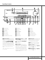
HK 3470 Stereo Receiver OWNER’S MANUAL MUTE T-MON AUTO TUNED ST MEMORY PRESET SLEEP VMAx ® ® Power for the digital revolution.™ HK 3470 Stereo Receiver 3 3 4 5 7 8 10 12 14 14 14 14 15 16 17 19 19 19 20 Introduction Safety Information Unpacking Front Panel Controls Front Panel Information Display Rear Panel Connections Remote Control Functions Installation and Connections Operation Basic Operation Source Selection Tuner Operation Tape Recording Remote Control Operation Programming the Remote Memory Backup Processor Reset Troubleshooting Guide Technical Specifications Typographical Conventions In order to help you use this manual with the remote control, front panel controls and rear panel connections, certain conventions have been used. EXAMPLE – (bold type) indicates a specific remote control or front panel button, or rear panel connection jack EXAMPLE – (OCR type) indicates a message that is visible on the front panel information display EXAMPLE – (outlined type) indicates a lit indicator in the front panel information display 1 – (number in a square) indicates a specific front panel control å – (letter in a circle) indicates a button or indicator on the remote ¡ – (number in a circle) indicates a rear panel connection A – (letter in a square) indicates an indicator in the front panel display 2 TABLE OF CONTENTS Introduction Congratulations! With the purchase of the Harman Kardon HK 3470 you are about to begin many years of listening enjoyment. The HK 3470 has been custom-designed to provide all the excitement and power of rock, jazz and popular music, and every nuance of classical selections. While sophisticated systems are hard at work within the HK 3470 to make all of this happen, hookup and operation are simple. Color-keyed connections and a comprehensive remote control make the HK 3470 easy to use. To obtain maximum enjoyment from your new receiver, we urge you to take a few minutes to read through this manual. This will ensure that connections to speakers, source playback units and other external devices are made properly. In addition, a few minutes spent learning the functions of the various controls will enable you to take advantage of all the power the HK 3470 is able to deliver. If you have any questions about this product, its installation or operation, please contact your dealer, your best local source of information. Description and Features Harman Kardon’s HK 3470 is the world’s first stereo receiver to offer VMAx®. VMAx is a proprietary signal-processing technique that creates an open, spacious sound field when only two loudspeakers are available. VMAx circuitry is able to decode the ambience of a concert hall or theater from a stereo recording. The HK 3470 is a full-featured stereo receiver, with five inputs and an FM Stereo/FM/AM tuner with capabilities that provide for the utmost flexibility. A high-quality phono input is available so that you may continue to enjoy your existing record collection as well as the latest CD recordings. The HK 3470’s powerful amplifier uses traditional Harman Kardon High-Current Design philosophies to meet the wide dynamic range of any program selection. Harman Kardon invented the high-fidelity receiver more than forty-seven years ago. With state-of-the-art features and time-honored circuit designs, the HK 3470 is one of the finest receivers ever offered by Harman Kardon. ■ Harman Kardon-Designed HighCurrent, Ultrawide-Bandwidth Amplifier ■ VMAx Processing Mode – Exclusive to Harman Kardon Receivers ■ Phono Input Section ■ Speaker 1/Speaker 2 Outputs for HighQuality Sound in Two Locations ■ Pre-Out/Main-In Jacks for Use With External Amplifiers, Equalizers or Speaker Processors ■ Programmable Learning Remote Control ■ Subwoofer Outputs Important Safety Information Verify Line Voltage Before Use Your HK 3470 has been designed for use with 120-volt AC current. Connection to a line voltage other than that for which it is intended can create a safety and fire hazard, and may damage the unit. If you have any questions about the voltage requirements for your specific model, or about the line voltage in your area, contact your selling dealer before plugging the unit into a wall outlet. Do Not Use Extension Cords To avoid safety hazards, use only the power cord attached to your unit. We do not recommend that extension cords be used with this product. As with all electrical devices, do not run power cords under rugs or carpets or place heavy objects on them. Damaged power cords should be replaced immediately with cords meeting factory specifications. Handle the AC Power Cord Gently When disconnecting the power cord from an AC outlet, always pull the plug – never pull the cord. If you do not intend to use the unit for any considerable length of time, disconnect the plug from the AC outlet. CAUTION RISK OF ELECTRIC SHOCK DO NOT OPEN CAUTION: To prevent electric shock, do not use this (polarized) plug with an extension cord, receptacle or other outlet unless the blades can be fully inserted to prevent blade exposure. The lightning flash with arrowhead symbol, within an equilateral triangle, is intended to alert the user to the presence of uninsulated “dangerous voltage” within the product’s enclosure that may be of sufficient magnitude to constitute a risk of electric shock to persons. The exclamation point within an equilateral triangle is intended to alert the user to the presence of important operating and maintenance (servicing) instructions in the literature accompanying the appliance. 3 INTRODUCTION Safety Information Do Not Open the Cabinet There are no user-serviceable components inside this product. Opening the cabinet may present a shock hazard, and any modification to the product will void your guarantee. If water or any metal object such as a paper clip, wire or staple accidentally falls inside the unit, disconnect it from the AC power source immediately and consult an authorized service station. CATV or Antenna Grounding If an outside antenna or cable system is connected to this product, be certain that it is grounded so as to provide some protection against voltage surges and static charges. Section 810 of the National Electrical Code, ANSI/NFPA No. 70-1984, provides information with respect to proper grounding of the mast and supporting structure, grounding of the lead-in wire to an antenna discharge unit, size of grounding conductors, location of antenna discharge unit, connection to grounding electrodes and requirements of the grounding electrode. NOTE TO CATV SYSTEM INSTALLER: This reminder is provided to call the CATV (Cable TV) system installer’s attention to article 820-40 of the NEC that provides guidelines for proper grounding and, in particular, specifies that the cable ground shall be connected to the grounding system of the building, as close to the point of cable entry as possible. Installation Location ■ To ensure proper operation and to avoid the potential for safety hazards, place the unit on a firm and level surface. When placing the unit on a shelf, be certain that the shelf and any mounting hardware can support the weight of the product. ■ Make certain that proper space is provided both above and below the unit for ventilation. If this product will be installed in a cabinet or other enclosed area, make certain that there is sufficient air movement within the cabinet. Under some circumstances a fan may be required. ■ Do not place the unit directly on a carpeted surface. ■ Avoid installation in extremely hot or cold locations, or an area that is exposed to direct sunlight or heating equipment. 4 SAFETY INFORMATION ■ Avoid moist or humid locations. ■ Do not obstruct the ventilation slots on the top of the unit or place objects directly over them. Cleaning When the unit gets dirty, wipe it with a clean, soft, dry cloth. If necessary, wipe it with a soft cloth dampened with mild soapy water, then a fresh cloth with clean water. Wipe dry immediately with a dry cloth. NEVER use benzene, aerosol cleaners, thinner, alcohol or any other volatile cleaning agent. Do not use abrasive cleaners, as they may damage the finish of metal parts. Avoid spraying insecticide near the unit. Moving the Unit Before moving the unit, be certain to disconnect any interconnection cords with other components and make certain that you disconnect the unit from the AC outlet. Important Information for the User NOTE: This equipment has been tested and found to comply with the limits for a Class-B digital device, pursuant to Part 15 of the FCC Rules. The limits are designed to provide reasonable protection against harmful interference in a residential installation. This equipment generates, uses and can radiate radio-frequency energy and, if not installed and used in accordance with the instructions, may cause harmful interference to radio communication. However, there is no guarantee that harmful interference will not occur in a particular installation. If this equipment does cause harmful interference to radio or television reception, which can be determined by turning the equipment off and on, the user is encouraged to try to correct the interference by one or more of the following measures: ■ Reorient or relocate the receiving antenna. ■ Increase the separation between the equipment and receiver. ■ Connect the equipment into an outlet on a circuit different from that to which the receiver is connected. ■ Consult the dealer or an experienced radio/TV technician for help. This device complies with Part 15 of the FCC Rules. Operation is subject to the following two conditions: (1) this device may not cause harmful interference and (2) this device must accept interference received, including interference that may cause undesired operation. NOTE: Changes or modifications may cause this unit to fail to comply with Part 15 of the FCC Rules and may void the user’s authority to operate the equipment. Unpacking The carton and shipping materials used to protect your new receiver during shipment were specially designed to cushion it from shock and vibration. We suggest that you save the carton and packing materials for use in shipping if you move, or should the unit ever need repair. To minimize the size of the carton in storage, you may wish to flatten it. This is done by carefully slitting the tape seams on the bottom and collapsing the carton down to a more twodimensional appearance. Other cardboard inserts may be stored in the same manner. Packing materials that cannot be collapsed should be saved along with the carton in a plastic bag. If you do not wish to save the packaging materials, please note that the carton and other sections of the shipping protection are recyclable. Please respect the environment and discard those materials at a local recycling center. Front Panel Controls 27 25 26 24 AUTO TUNED ST MUTE T-MON 23 MEMORY PRESET SLEEP VMAx VMAx 1 2 3 7 5 4 6 8 9 ! # ) @ $ % & ^ ( * 21 20 22 1 Main Power Switch 2 System Power Control 3 Power Indicator 4 Headphone Jack 5 Mute 6 Speaker 1 Selector 7 Speaker 2 Selector 8 Phono Input Selector 9 T-Mon (Tape Monitor) Input Selector ) Tuning Button ! Tape Input Selector @ Preset Scan # CD Input Selector $ Aux Input Selector % Preset Selector ^ VMAx Selector & FM/AM Selector * FM Mode Selector ( Sleep Button Ó Bass Control Ô Treble Control Balance Control Ò Volume Control Ú Volume/Mute Indicator Û Main Information Display Ù Speaker Selection Indicators ı Remote Sensor Window 1 Main Power Switch: Press this button to apply power to the HK 3470. When the switch is pressed in, the unit is placed in a Standby mode, as indicated by the Power Indicator 3 surrounding the System Power Control 2. This button MUST be pressed in to operate the unit. To turn the unit off and prevent the use of the remote control, this switch should be pressed until it pops out from the front panel so that the word “OFF” may be read at the top of the switch. 2 System Power Control: When the Main Power Switch 1 is “ON,” press this button to turn on the HK 3470; press it again to turn the unit off. Note that the Power Indicator 3 surrounding the switch will turn green when the unit is on. 4 Headphone Jack: This jack may be used to listen to the HK 3470’s output through a pair of headphones. Be certain that the headphones have a standard 1⁄4" stereo phone plug. NOTE: In normal operation this switch is left in the “ON” position. 3 Power Indicator: This LED will light in amber when the unit is in the Standby mode to signal that the unit is ready to be turned on. When the unit is in operation, the indicator will briefly turn red, and then change to green. A red indicator during normal operation means that the unit is in the Protect mode, and should be turned off and then checked for a possible speaker-wire short circuit. 5 Mute: Press this button to momentarily silence the speaker output of the HK 3470. 6 Speaker 1 Button: Press this button to turn the speakers connected to the Speaker 1 output terminals ‡ on or off. 7 Speaker 2 Button: Press this button to turn the speakers connected to the Speaker 2 output terminals ° on or off. 5 FRONT PANEL CONTROLS Front Panel Controls 8 Phono Input Selector: Press this button to select the output of a turntable that is connected to the Phono inputs §. 9 T-Mon (Tape Monitor) Input Selector: Press this button to listen to the output of a tape recorder connected to the Tape Monitor inputs ª. The T-Mon indicator will light to indicate that the input source is being monitored when the HK 3470 is connected to a three-head tape deck or another unit with offhead playback. ) Tuning Button: Press the left side of the button to tune lower-frequency stations and the right side of the button to tune higher-frequency stations. When a station with a strong signal is tuned, the TUNED indicator will light in the Main Information Display Û. A brief (1/2 second) press of the button will manually tune to the next frequency increment, while pressing and holding the button for a longer period will automatically tune to the next station with a signal strong enough for acceptable reception. ! Tape Input Selector: Press this button to listen to the output of a tape recorder or other device connected to the Tape 2 inputs ⁄. @ Preset Scan: Press this button to automatically scan through the stations that have been programmed in the HK 3470’s memory. The tuner will play five seconds of each station before moving to the next preset station. To stop the scan when the desired station is heard, press the button again. (See page 15 for more information on the tuner memory system.) # CD Input Selector: Press this button to listen to the output of a CD player connected to the CD inputs ¶. $ Aux Input Selector: Press this button to listen to the output of a device connected to the Aux inputs •. % Preset Selector: Press this button to step up or down through the list of stations that has been entered into the preset memory. (See page 15 for more information on tuner programming.) ^ VMAx Selector: Press this button to engage VMAx processing of a stereo input. The VMAx Mode Indicator A will light, and you will notice a wider, more spacious sound field. In order to obtain maximum benefit, you should 6 FRONT PANEL CONTROLS be seated midway between the two loudspeakers, and the same distance from the speakers as the speakers are from each other. The speakers must be placed facing parallel and evenly with each other so that their baffles are in the same plane. Press the button again to return to Stereo mode. & FM/AM Selector: Press this button to select the tuner as the input to the receiver. When the tuner is in use, press this button to change between the AM and FM frequency bands. * FM Mode Selector: Press this button to select the Stereo or Mono mode for FM tuning. In the STEREO mode, a Stereo indicator will light in the Main Information Display Û, and stereo reception will be provided when stations are transmitting stereo signals. In the MONO mode, the left and right signals from stereo broadcasts will be mixed together and reproduced through all channels. Select MONO for better reception of weak signals. VMAx will have no effect in MONO mode. ( Sleep Button: Press this button to place the unit in the Sleep mode. Each press of the button selects the amount of time that will remain before the unit automatically goes into the Standby mode, as shown in the Main Information Display Û, in the following order: 90 min 80 min 70 min 60 min 50 min 40 min 30 min 20 min 10 min OFF Ó Bass Control: Turn this control to modify the low-frequency output of the left and right channels by as much as ±10dB. Set this control to a suitable position for your taste and room acoustics. Ô Treble Control: Turn this control to modify the high-frequency output of the left and right channels by as much as ±10dB. Set this control to a suitable position for your taste and room acoustics. Balance Control: Turn this control to change the relative volume for the left and right channels. Ò Volume Control: Turn the knob clockwise to increase volume, counterclockwise to decrease the volume. Ú Volume/Mute Indicator: This indicator will glow green when the HK 3470 is turned on. Its position will enable you to judge the relative volume of the unit even when the speakers are muted or turned off. When the indicator is pointing toward the left, as in an “8 o’clock” position, the volume is low; when it is pointing to the right, as in a “3 o’clock” position, the volume is loud. When the unit has been muted by pressing the Mute button 5, the indicator will flash. Û Main Information Display: This display delivers messages and status indications to help you operate the receiver. Ù Speaker Selection Indicators: These indicators light as a green LED next to the designation for each speaker pair to show when they are active. Press the Speaker 1 6 or Speaker 2 7 Selectors to activate either pair of speakers. Both sets of speakers may be selected simultaneously as long as all speakers have a nominal impedance of 8 ohms or greater. However, occasionally the actual impedance will vary, depending upon the program material. If the impedance drops to a point where there may be potential damage to the equipment, the HK 3470 will go into protect mode. ı Remote Sensor Window: The sensor behind this window receives infrared signals from the remote control. Aim the remote at this area and do not block or cover it unless an external remote sensor is installed. Front Panel Information Display K J I H G F AUTO TUNED ST MUTE T-MON E DC B MEMORY PRESET SLEEP VMAx A A VMAx Mode Indicator B Preset Number/Sleep Timer C Preset Indicator D Sleep Indicator E Memory Indicator F Stereo Indicator G Tuned Indicator H Auto Indicator A VMAx Mode Indicator: This indicator lights when the VMAx mode is in use. (See page 14 for a description of the VMAx Mode.) G Tuned Indicator: This indicator lights when a station is being received with sufficient signal strength to provide acceptable listening quality. B Preset Number/Sleep Timer: When the tuner is in use, these numbers indicate the specific preset memory location in use. (See page 15 for more information on preset stations.) When the Sleep function is in use, these numbers show how many minutes remain before the unit goes into the Standby mode. H Auto Indicator: This indicator lights when the tuner’s Auto mode is in use. C Preset Indicator: This indicator lights when the tuner is in use to show that the Preset Number/Sleep Timer B is showing the station’s preset memory number. (See page 15 for more information on tuner presets.) D Sleep Indicator: This indicator lights when the Sleep function is in use. The numbers in the Preset Number/Sleep Timer Indicators will show the minutes remaining before the HK 3470 goes into the Standby mode. (See page 14 for more information on the Sleep function.) E Memory Indicator: This indicator flashes when entering presets and other information into the tuner’s memory. F Stereo Indicator: This indicator lights when an FM station is being tuned in stereo. I Main Information Display J Tape Monitor (T-Mon) Indicator K Mute Indicator I Main Information Display: This display shows messages relating to the status, input source, tuner or other aspects of the HK 3470’s operation. J Tape Monitor (T-Mon) Indicator: When used with three-head cassette decks, or other recording devices that offer immediate playback of the recording as it is being made, the HK 3470 allows you to monitor a recording rather than merely listening to the input source, or waiting until the recording session is complete in order to hear the recording. Press the Tape Monitor Input Selector 9ç, and the T-Mon Indicator J will light to remind you that you are monitoring the recording. Press the Tape Monitor Input Selector 9ç again to hear the input source. K Mute Indicator: This indicator lights to remind you that the HK 3470’s output has been silenced by pressing the Mute button 5 ®. Press the Mute button again to return to the previously selected output level. 7 FRONT PANEL INFORMATION DISPLAY Rear Panel Connections HK3470 ¡ AM LOOP ™ £ FM 75 Ω SPEAKER 1 (8 Ohms) (120V, 60Hz) RIGHT PHONO ¢ ∞ AC 120V 60HZ LEFT GND CD AUX TAPE MON. TAPE 2 MAIN IN PRE OUT SUB OUT 400W IN L OUT R IN IN IN PLAY • § ¶ REC. OUT PLAY ‚ ª ¡ AM Antenna ™ FM Antenna £ Phono Ground ¢ Remote IR In ∞ Remote IR Out § Phono Inputs ¶ CD Inputs 8 REAR PANEL CONNECTIONS REC. OUT MONO ¤ ⁄ › ‹ SPEAKER 2 (8 Ohms) fl fi ‡ • Aux Inputs ª Tape Monitor Play/In ‚ Tape Monitor Record/Out ⁄ Tape 2 Play/In ¤ Tape 2 Record/Out ‹ Main In › Pre-Out/Main-In Jumper Pins ° a · fi Preamp Out fl Subwoofer Out ‡ Speaker 1 Terminals ° Speaker 2 Terminals · Accessory Outlets a Power Cable Rear Panel Connections ¡ AM Antenna: Connect the AM loop antenna supplied with the receiver to these terminals. If an external AM antenna is used, make connections to the AM and GND terminals in accordance with the instructions supplied with the antenna. ™ FM Antenna: Connect an indoor or external FM antenna to this terminal. £ Phono Ground: Connect the ground wire from a turntable to this terminal to reduce system hum. ¢ Remote IR In: If the HK 3470’s front panel IR sensor is blocked due to cabinet doors or other obstructions, an external IR sensor may be used. Connect the output of the sensor to this jack. ∞ Remote IR Out: This connection permits the IR sensor in the receiver to serve other remote-controlled devices. Connect this jack to the “IR IN” jack on Harman Kardon or other compatible equipment. § Phono Inputs: Connect the outputs of your turntable or tonearm to these jacks. Note that only turntables with Moving Magnet (MM) type cartridges may be used. ¶ CD Inputs: Connect these jacks to the output of a compact disc player or CD changer. • Aux Inputs: Connect these jacks to the line-level output of any audio device such as a TV, cable converter, portable audio player or MP3 player. ª Tape Monitor Play/In: Connect these jacks to the Play/Out jacks of an audio recorder. NOTE: When these jacks are connected to a three-head recorder or another device with offhead playback, it will be possible to monitor the source being recorded. ⁄ Tape 2 Play/In: Connect these jacks to the PLAY/OUT jacks of a second audio recorder. ¤ Tape 2 Record/Out: Connect these jacks to the Rec/In jacks of a second audio recorder. ‹ Main In: These jacks are the input to the HK 3470’s power amplifier. Unless an external power amplifier is used, the jumper pins should remain connected to the Preamp Out jacks fi. › Pre-Out/Main-In Jumper Pins: These pins connect the receiver’s preamp and amplifier sections. Unless an external amplifier, equalizer or speaker processor is used, they should be left connected. See page 13 for more information on external amplifier connections. ° Speaker 2 Terminals: Connect these terminals to the appropriate terminals on your speakers. · Accessory Outlets: These outlets may be used to power low-current draw devices such as CD players or cassette decks. The power to these outlets remains on as long as the receiver itself is on. When the receiver is turned off, or placed in the Standby mode, power to these outlets is removed. NOTE: The power consumption of the devices plugged into these outlets should not exceed 100 watts. a Power Cable: Connect the AC plug to a nonswitched AC wall output. fi Preamp Out: These jacks provide an output for the left and right channels to an optional external amplifier. In normal operation, unless an external power amplifier is used, the jumper pins should remain connected to the Main In jacks ‹. fl Subwoofer Out: Connect these jacks to the line-level input of a powered subwoofer. If an external subwoofer amplifier is used, connect this jack to the subwoofer amplifier input. When a single, mono subwoofer is used, make the connection to the bottom jack. ‡ Speaker 1 Terminals: Connect these terminals to the appropriate terminals on your speakers. ‚ Tape Monitor Record/Out: Connect these jacks to the Rec/In jacks of an audio recorder. 9 REAR PANEL CONNECTIONS Remote Control Functions å ∫ ç ∂ ≠ ƒ © ˙ î ∆ ˚ ¬ µ Ñ ø π œ ® ß † Ü √ ∑ ≈ ¥ Ω Main Power On Main Power Off Source Selectors Preset Up/Down Transport Controls Disc Skip Sleep Button Dimmer Button Tuning Direct Button Numeric Keys Auto Preset Secondary Control Cover Clear Button Memory Button Master Volume P. Scan Button Mute Button FM Mode Button VMAx Selector Tuning Up/Down Learn Button Speaker 1 Selector Speaker 2 Selector Transmitter Window LED Indicator ¥ Ω ∫ å MAIN POWER ON OFF SPEAKER 1 2 PHONO TAPE MON TAPE 2 LEARN CD AUX AM FM ≈ ∑ √ ç DWN - PRESET - UP DWN - TUNING - UP Ü ∂ / ≠ DISC SKIP FM MODE VMAx P. SCAN MUTE † ƒ ® SLEEP © MASTER VOL. TUNING DIMMER ß œ π ˙ ∆ DIRECT ˚ ¬ AUTO PRESET MEMORY 1 2 3 4 5 6 7 8 9 0 µ HK 3470 RC 10 REMOTE CONTROL FUNCTIONS CLEAR ø Ñ Remote Control Functions å Main Power On: When the HK 3470 is in the Standby mode, as indicated by the Power Indicator 3 glowing amber, press this button to turn the HK 3470 on. ∫ Main Power Off: When the HK 3470 is turned on, press this button to place it in the Standby mode. Note that in this mode, the unit is still connected to AC Power. ç Source Selectors: Press these buttons to select an input source for the HK 3470. ∂ Preset Up/Down: When the tuner is in use, these buttons scroll through the stations that have been programmed into the HK 3470’s memory. These buttons also control the track Skip Up and Down on compatible Harman Kardon compact disc players and changers. ≠ Transport Controls: These buttons are used to control Play, Play Forward, Play Reverse, Stop, Pause and Record functions on compatible Harman Kardon compact disc players/changers and cassette tape decks. Also, when a compatible Harman Kardon compact disc player or changer, or cassette deck, has been selected using the Source Selectors ç, additional transport control functions are available using the Preset Up/Down ∂ and Tuning Up/Down ü buttons. ƒ Disc Skip: These buttons do not have any functions when controlling the HK 3470, but they operate the Disc Skip functions of compatible Harman Kardon compact disc changers. © Sleep Button: Press this button to place the unit in the Sleep mode. Each press of the button selects the amount of time that will remain before the unit will automatically go into the Standby mode, as shown in the Main Information Display Û, in the following order: 90 min 80 min 70 min 60 min 50 min 40 min 30 min 20 min 10 min OFF ˙ Dimmer Button: Press this button once to reduce the brightness of the front panel display to half the normal intensity. Press it again to turn the front panel display completely off. When the display is completely off, press the button to return to normal brightness. î Tuning: Press these buttons to tune up or down through a selected frequency band. ∆ Direct Button: Press this button to select a radio station by entering its frequency using the Numeric Keys K. (See page 15 for more information.) ® Mute Button: Press this button to momentarily silence the HK 3470. ˚ Numeric Keys: These buttons serve as a ten-button numeric keypad to enter tuner preset positions or to tune stations directly. ß FM Mode Button: Press this button when the tuner is in use in the FM band to switch to monaural reception if the station is weak and noisy. (See page 15 for more information.) ¬ Auto Preset: When the tuner and FM band have been selected, this button may be used to automatically program the tuner presets for all active stations. To start the auto preset scan, press and hold the button. Note that the MEMO and PRESET indicators will flash. After a few seconds, the tuner will start to “look” for active stations, as shown by increasing frequency numbers in the Main Information Display. Release the button and note that the tuner will briefly stop at each active station and add a preset number to the memory. If the FM tuner finds fewer than 30 FM stations with acceptable signal strength, the Auto Preset tuning will scan two more cycles or until the remaining vacant preset memory spaces have been filled with those found in the first scan. The scan will stop when all 30 preset memory spaces have been filled or when three scans through the band have been completed. µ Secondary Control Cover: This sliding cover normally is in the “up” position so that it hides the secondary controls (the Direct button, Numeric Keys, Auto Preset button, Clear button and Memory button) ∆˚¬Ñø. To access these controls, place your thumb on the small recessed area at the top center of the control, and gently press the cover down and towards you. Ñ Clear Button: This button is used to clear preset memory information for the HK 3470’s tuner. (See page 15 for more information on tuner presets.) ø Memory Button: Press this button to open a memory position that stores a preset location for the HK 3470’s tuner. (See page 15 for more information on tuner presets.) π Master Volume: Press these buttons to raise or lower the HK 3470’s volume. œ P. Scan Button: Press this button to automatically scan through the list of stations that are programmed into the HK 3470’s tuner memory. When the button is pressed, each preset station will play for five seconds before the next station is selected. Press the button again when the desired station is heard to stop the preset scan. † VMAx Selector: Press this button to engage VMAx processing of a stereo input. The VMAx Mode Indicator A will light, and you will notice a wider, more spacious sound field. In order to obtain maximum benefit, you should be seated midway between the two loudspeakers, and the same distance from the speakers as the speakers are from each other. The speakers must be placed facing parallel and evenly with each other so that their baffles are in the same plane. Press the button again to return to Stereo mode. ü Tuning Up/Down: When the tuner is in use, these buttons will tune up or down through the selected frequency band. A brief (1⁄2 second) press of the button will manually tune to the next frequency increment, while pressing and holding the button for a longer period will automatically tune to the next station with a signal strong enough for acceptable reception. These buttons will also control Fast Forward and Fast Reverse (or Rewind) for compatible Harman Kardon compact disc players/changers and cassette tape decks. √ Learn Button: This button is used when you wish to program codes from another device’s remote control into the HK 3470 remote. The simple procedure is described on page 18. ∑ Speaker 1 Selector: Press this button to turn the speakers connected to the Speaker 1 Output terminals ‡ on or off. ≈ Speaker 2 Selector: Press this button to turn the speakers connected to the Speaker 2 Output terminals ° on or off. ¥ Transmitter Window: Point this area of the remote toward the receiver when using the remote. Ω LED Indicator: This indicator will light or blink to confirm various steps in the learning process as the HK 3470 remote is programmed. It will also flicker when a key is pressed during normal operation to indicate that it is transmitting an infrared code. 11 REMOTE CONTROL FUNCTIONS Installation and Connections System Installation After unpacking the unit and placing it on a solid surface capable of supporting its weight, you will need to make the connections to your audio and video equipment. These steps need to be done only when the receiver is first installed or when a change is made to the input source equipment. Audio Equipment Connections We recommend that you use high-quality interconnect cables when making connections to source equipment and recorders to preserve the quality of the signals. When making connections to audio source equipment or speakers it is always a good practice to unplug the unit from the AC wall outlet. This prevents any possibility of accidentally sending audio or transient signals to the speakers that may damage them. 1. Connect the analog output of a CD player to the CD inputs ¶. NOTE: When the CD player has both fixed and variable audio outputs, it is best to use the fixed output unless you find that the input to the receiver is so low that the sound is noisy, or so high that the signal is distorted. 2. Connect the Play/Out jacks of a cassette deck, CDR, MD or other audio recorder to the Tape Monitor In jacks ª. Connect the Record/In jacks on the recorder to the Tape Monitor Out jacks ‚ on the HK 3470. When the tape deck connected to these jacks is a three-head unit or has off-head playback, it will be possible to monitor the output of the source being recorded. 3. Connect the output of a second audio recorder, CDR, VCR or other line-level audio device to the Tape 2 Play/In jacks ⁄. If a recorder is used, connect its Rec/In jacks to the matching Tape 2 Record outputs ¤. 4. The output of any electronics product with a line-level output, such as a TV set, satellite receiver or DVD, may be connected to the Aux jacks •. 5. Connect the outputs of a turntable with a moving magnet cartridge to the Phono inputs §. To insure that the phono playback is noisefree, connect the ground wire from the tonearm to the Phono Ground terminal £. 12 INSTALLATION AND CONNECTIONS 6. Assemble the AM Loop Antenna supplied with the unit as shown below. Connect it to the AM screw terminals ¡. 7. Connect an FM antenna to the FM Antenna connection ™. The FM antenna may be an external roof antenna, an inside powered or wire lead antenna or a connection from a cable TV system. Note that if the antenna or connection uses 300-ohm twin-lead cable, you must use the 300-ohm-to-75-ohm adapter supplied with the unit to make the connection. Speaker and Output Connections To ensure that all the audio signals are carried to your speakers without loss of clarity or resolution, we suggest that you use high-quality speaker cable. Many brands of cable are available, and the choice of cable may be influenced by the distance between your speakers and the receiver, the type of speakers you use, personal preferences and other factors. Your dealer or installer is a valuable resource for help in selecting the proper cable. Regardless of the brand of cable selected, we recommend that you use a cable constructed of fine, multistrand copper with a gauge of AWG14 or smaller. Remember that in specifying cable, the lower the number, the thicker the cable. Cable with a gauge of 16 may be used for short runs of less than ten feet. We do not recommend that you use cables with an AWG equivalent of 18 or higher due to the power loss and degradation in performance that will occur. Cables that are run inside walls should have the appropriate markings to indicate listing with UL, CSA or other appropriate testing agency standards. Questions about running cables inside walls should be referred to your installer or a licensed electrical contractor who is familiar with the NEC and/or the applicable local building codes in your area. When connecting wires to the speakers, be certain to observe proper polarity. Remember to connect the “negative” or “black” wire to the same terminal on the receiver and the speaker. Similarly, the “positive” or “red” wire should be connected to the like terminals on the HK 3470 and speaker. We also recommend that the length of cable used to connect speaker pairs be identical. For example, use the same length piece of cable to connect the Speaker 1 left and right or Speaker 2 left and right speakers, even if the speakers are a different distance from the HK 3470. NOTE: While most speaker manufacturers adhere to an industry convention of using black terminals for negative and red ones for positive, some manufacturers may vary from this configuration. To assure proper phase, and optimal performance, consult the identification plate on your speaker, or the speaker’s manual to verify polarity. If you do not know the polarity of your speaker, ask your dealer for advice before proceeding, or consult the speaker’s manufacturer. Connect the speakers using the following steps: 1. Connect the main speakers to the Speaker 1 terminals ‡. 2. Connect a second set of speakers, or speakers that are in a second room location, to the Speaker 2 terminals °. 3. When an optional, powered subwoofer is used, connect the outputs of the left and right Subwoofer Out jacks fl to the line-level inputs of the subwoofer. When the subwoofer’s amplifier has stereo inputs, run interconnects from both jacks. When the subwoofer has a mono input only, use the bottom output jack for the connection. If the subwoofer has only speaker-level inputs and outputs, connect the Speaker 1 terminals ‡ to the speaker-level inputs on the subwoofer, and then connect the speaker-level outputs on the subwoofer to your main left and right speakers, following the instructions provided with the subwoofer. When a passive subwoofer is used, these connections will be made to the optional amplifier that powers the subwoofer. Installation and Connections System and Power Connections The HK 3470 is designed for flexible use with external control components and power amplifiers. These connections are easy to make during an initial installation, or at a later date should you choose to upgrade your system. Alternatively, you may connect the external device to the Tape Monitor Loop. Connect the Tape Monitor Record/Out jacks ‚ to the inputs of the external device, and connect the outputs of the device to the Tape Monitor Play/In jacks ª. Remote Control Extension If the receiver is placed behind a solid or smoked glass cabinet door, the obstruction may prevent the remote sensor from receiving commands. In this event, an optional remote sensor may be used. Connect the output of the remote sensor to the Remote IR In jack ¢. AC Power Connections The Accessory Outlets · receive power as long as the receiver is turned on. Power to these outlets is removed when the unit is in the Standby mode, or when the Main Power Switch 1 is in the “OFF” position. If other components are also prevented from receiving remote commands, only one sensor is needed. They may use this unit’s sensor or a remote eye by running a connection from the Remote IR Out jack ∞ to the Remote In jack on Harman Kardon or other compatible equipment. External Audio Power Amplifier Connections If desired, an optional, external amplifier may be used in place of the HK 3470’s internal power amplifier. To connect an external power amplifier, first remove the Pre-Out/Main-In Jumper Pins › that connect the Preamp Out fi and Main In ‹ jacks on the rear panel. Keep the jumpers in a safe place should they be needed at a later time. Speaker Placement For optimal listening enjoyment, and for soundfield reproduction that best re-creates the original recording, it is good practice to place the speakers so that they form a triangle with the speakers at the front of the room, and the preferred listening spot at the third point of the triangle. The distance between each speaker and the listener should be identical. For example, if the speakers are 10 feet from one another, each of the speakers should optimally be placed so that they are also 10 feet from the listener. It is also desirable to place speakers so that their tweeters, or highfrequency drivers, are aimed at ear height when you are seated in the listening position. Left Front Speaker To optimize the sound field, or to suit your listening room environment, you may find that some experimentation is required to find the correct location. Ideally, pans from left to right across the front of the room should sound smooth, and instruments should appear to be coming from the proper location within an orchestra. The placement of subwoofers should be done as suggested in the manufacturer’s instructions. In general, subwoofers often produce best results when they are placed in the corner of a room, along the same wall as the speakers, but optimal placement will vary widely depending on room size, the subwoofer type and the placement of rugs and furniture in a room. It may be helpful to temporarily position the subwoofer in the usual listening position, then walk around the room while program material is playing until the bass reproduction sounds best to your ears. That location is likely to be the optimum position for the subwoofer. Finally, when all connections are complete, plug the power cord into a nonswitched 120-volt AC wall outlet. You’re ready to enjoy the HK 3470! Right Front Speaker Using high-quality audio interconnect cables, connect the Preamp Out jacks fi to the input jacks on your power amplifier. Make certain to match the right output to the right input and the left output to the left input. Note that when an external power amplifier is used, no special adjustments are required. All volume and other control adjustments are made using the standard front panel or remote controls. A good starting point for speaker placement is to make the distance between the two speakers and the distance between either speaker and the listener identical. If you wish to use external processing equipment, such as an equalizer, you may connect the device to the preamp-out and main-in jacks by removing the Preamp-Out/Main-In Jumper Pins › and connecting the Preamp Out fi jacks to the inputs of the external device, and the outputs of the device to the Main In ‹ jacks. 13 INSTALLATION AND CONNECTIONS Operation Basic Operation The HK 3470 is simple to operate, and very similar to stereo receivers you may have used in the past. This section will explain the use of several features that may be new to you. • Install the two supplied AAA batteries in the remote as shown. Be certain to observe the (+) and (–) polarity indicators shown in the bottom of the battery compartment. • When using the HK 3470 for the first time, it will be necessary to press the Main Power button 1 on the front panel to turn the unit on. This places the unit in a standby mode, as indicated by the amber color of the Power Indicator 3. Once the unit is in standby, you may begin a listening session by pressing the System Power Control 2 on the front panel or the Main Power On button å on the remote. Note that the Power Indicator 3 will turn red, then green. This will turn the unit on and return it to the input source that was last used. The unit may also be turned on from standby by pressing any of the Source Selector buttons on the front panel 8 9 ! # $ & or remote ç. To turn the unit off at the end of a listening session simply press the System Power Control 2 on the front panel or the Main Power Off button ∫ on the remote. This places the unit in the Standby mode, and the Power Indicator 3 will turn amber to remind you that the unit is ready for operation when a power command is received from the remote. When the remote is used to turn the unit “off”, it is actually placing the system in a standby mode, as indicated by the amber color of the Power Indicator 3. When you will be away from home for an extended period of time it is always a good idea to completely turn the unit off using the front panel Main Power Switch 1. 14 OPERATION • To dim the brightness of the front panel display, press the Dimmer button ˙ on the remote. The first press will dim the lights to half normal. A second press will turn the display completely off. Press the Dimmer button ˙ again to restore the display to normal brightness. Source Selection • To select a source at any time, press any of the Source Selector buttons on the remote ç or front panel 8 9 ! # $ &. indicated by a lit green LED in the Speaker Indicators Ù display. Both sets of speakers may be turned off for private headphone listening. • To program the HK 3470 for automatic turnoff, press the Sleep button on the front panel ( or remote ©. Each press of the button will increase the time before shutdown in the following sequence: 90 min 80 min 70 min 60 min 50 min 40 min 30 min 20 min 10 min OFF • During a listening session you may wish to adjust the Bass Ó, Treble Ô and Balance controls to suit your listening tastes. The sleep time will be displayed in the Main Information Display Û and it will count down until the time has elapsed. • Adjust the volume to a comfortable level using the front panel Volume Control Ò or remote Master Volume Up/Down π buttons. The volume level is displayed by the position of the Volume Indicator Ú. Think of the Volume Control knob Ò as the face of a clock, with the Volume Indicator Ú indicating the hour. The HK 3470 is playing at the minimum volume level when the Volume Indicator Ú points to 7 o’clock; when the Volume Indicator Ú points to 12 o’clock (straight up), the HK 3470 is playing at the maximum volume level. It is important that you make sure never to exceed this maximum volume level at any time, in order to avoid possible damage to your loudspeakers due to “clipping”, a type of distortion that is not audible to the human ear until it is severe enough to permanently damage most loudspeakers. It is also possible, depending upon the program material, for clipping to occur at volumes below the maximum volume level. When the programmed time has elapsed, the unit will automatically turn off. Note that the front panel display will dim to one-half brightness when the Sleep function is programmed. To cancel the Sleep function, press the Sleep button (© until the Sleep indicator numbers disappear and the Main Information Display shows the current source. Pressing any control button while the Sleep control is activated will momentarily return the Main Information Display to full brightness for increased legibility without interrupting the Sleep function. • To temporarily silence all speaker outputs, press the Mute button ®5. This will cut the output to all speakers, but it will not affect any recording or dubbing that may be in progress. When the system is muted, the MUTE indicator will light in the Main Information Display Û and the Volume/Mute indicator Ú will flash. Press the Mute button ®5 again to return to normal operation. • For private listening, plug the 1/4" stereo phone plug from a pair of stereo headphones into the front panel Headphone jack 4. • One or two separate sets of speakers may be connected to the HK 3470. To listen to one of the speaker sets, press the Speaker buttons 67 on the front panel corresponding to the desired speakers. The active speakers will be To take advantage of Harman Kardon’s exclusive VMAx mode, Press the VMAx button ^†. When the VMAx circuits are engaged, patented processing algorithms are used to create a three-dimensional sound space with the illusion of “phantom” speakers at center and surround positions. This spacious sound will simulate a surround-sound presentation without the need to add additional speakers. To return to standard stereo listening, press the VMAx button ^† again and note that the VMAx Mode Indicator A will go out. Tuner Operation The HK 3470’s tuner is capable of tuning AM, FM and FM Stereo broadcast stations. Stations may be tuned manually, or they may be stored as favorite station presets and recalled from a 30-position memory. Station Selection 1. Press the AM/FM & buttons on the front panel or on the remote ç to select the tuner as an input. 2. Press these buttons again at any time to switch between AM and FM. Operation 3. To select stations, press, and briefly hold, the Tuning button )Ü and the tuner will search for the next highest- or lowest-frequency station that has an acceptable signal. To tune to the next station, press the button again. Tap the Tuning button )Ü to advance one frequency increment at a time, or press and hold it to locate a specific station. When the TUNED indicator lights, the station is properly tuned and should be heard with clarity. 4. Stations may also be tuned directly by pressing the Direct button ∆, and then pressing the Numeric Keys ˚ that correspond to the station’s frequency. The desired station will automatically be tuned. NOTE: When the FM reception of a station is weak, audio quality will be increased by switching to Mono mode by pressing the FM Mode button * ß until the STEREO indicator goes out. Preset Tuning Up to 30 stations may be stored in the HK 3470’s memory for easy recall using the front panel controls or the remote. In order to program preset stations into memory, you must use the remote control. To enter a station into the memory, first tune the station using the steps outlined above. Then: 1. Press the Memory button ø on the remote. Note that the MEMO and PRESET indicators will light and flash in the Main Information Display. 2. Within five seconds, press the Numeric Keys ˚ corresponding to the location where you wish to store this station’s frequency. 3. Repeat the process after tuning any additional stations to be preset. Auto Preset • Preset stations may also be programmed automatically for the entire FM band. To automatically enter each station that may be tuned with acceptable quality into the HK 3470’s preset memories, first select the FM band. Next, press and briefly hold the Auto Preset button ¬ until the MEMO and PRESET indicators begin to flash, and the station frequency indication begins to increase. Release the button and note that the tuner will search the entire FM band, and stop briefly at each station that has acceptable signal strength. The HK 3470 will automatically assign a preset number to each station, and then search for the next station. The automatic scan process will stop when all 30 preset memory locations have been filled or the entire FM band has been scanned three times. NOTE: Using the automatic tuning mode in areas with more than 30 FM stations will completely fill the preset memories, and overwrite any previously memorized presets for either AM or FM stations. TIP: The automatic scan process may enter stations that you do not wish to retain in the memory, or it may enter a station on more than one frequency if the signal is too strong. These unwanted stations may be removed from the memory using the Preset Clear function outlined below. Recalling Preset Stations • To manually select a station previously entered in the preset memory, press the Numeric Keys ˚ that correspond to the desired station’s memory location. • To manually tune through the list of stored preset stations one by one, press the Preset buttons % ∂ on the front panel or remote. the preset number location in the Main Information Display. That memory location will now be empty, and you may program a different station to that location, or leave it empty. Tape Recording In normal operation, the audio source selected for listening through the HK 3470 is sent to the Tape Mon Out and Tape 2 Rec Out outputs. This means that any program you are listening to may be recorded simply by placing machines connected to the outputs for Tape Monitor ‚ or Tape 2 ¤ in the record mode. When a tape recorder with separate record and playback heads is used, you may monitor the output of the recording by selecting the Tape Monitor Input Selector 9 ç. Note that the T-Mon Indicator will light in the Main Information Display Û to remind you that you are listening to the record playback instead of the actual input source being recorded. IMPORTANT NOTE: Please make certain that you are aware of the copyright restrictions on any material you copy. • To automatically scan through the stations entered in the preset memory, press the Preset Scan button @ œ on the front panel or remote. The tuner will cycle through the list of preset stations, stopping for five seconds at each one. Press the button again to stop the scan at your desired station. Clearing Preset Stations Unwanted preset stations may be erased from the unit’s memory to make it easier to tune only those stations you want. To remove a preset station from the HK 3470’s tuner memory, first tune to the station using the Preset Scan button @ œ on the front panel or remote, or by entering the preset number directly, using the Numeric Keys ˚. When the preset station to be removed has been tuned, first press the Memory button ø. The MEMO and PRESET indicators in the Main Information Display will flash, and the actual preset number will disappear from the display. Next, press the Clear button Ñ within five seconds. The preset station will be removed from the memory, and the action will be confirmed by the brief appearance of the word CLEAR and 15 OPERATION Operation Using the Remote Control It is convenient to think of the functions of the remote control buttons in terms of “pages”, where each source device (e.g., CD player) represents its own page of remote functions. The result is that some of the keys will perform different functions depending upon which device page has been selected prior to pressing the key. Device pages are selected by pressing the Source Selectors ç, which also changes the input source selection on the HK 3470. Three of the device pages are factoryprogrammed to operate compatible Harman Kardon products. The Tape Monitor device page is programmed as a factory default to operate Harman Kardon cassette decks. The Tape 2 page defaults to Harman Kardon CD-R control codes. The CD page defaults to Harman Kardon CD player or changer control codes. Note that all of these keys may be programmed in the learning mode to transmit different remote codes to perform other functions and/or operate other devices. Please refer to the table below for specific information on the default functions of the affected keys for these devices. REMOTE BUTTON FUNCTIONS BUTTON TAPE MON Cassette deck control codes PRESET DWN REV. SKIP SKIP BACK REV. SKIP PRESET UP FWD. SKIP SKIP FORWARD FWD. SKIP TUNING DWN REW REV SEARCH REV SEARCH TUNING UP FF FWD SEARCH FWD SEARCH Rec./Pause REC / PAUSE RECORD PAUSE Stop STOP STOP STOP Rev. Play REV. PLAY RANDOM PLAY Fwd. Play FWD. PLAY PLAY PLAY DISK SKIP Up TRANSPORT SELECT DISC SKIP UP DISC SKIP UP DISK SKIP Down TRANSPORT SELECT DISC SKIP DOWN DISC SKIP DOWN FM MODE PRESET SCAN TAPE 2 CD Recorder control codes CD CD player/changer control codes TIME INTRO SCAN INTRO SCAN TUNING Up CDP SELECT TUNING Down CDR SELECT DIRECT TRACK DIRECT MEMORY PROGRAM AUTO PRESET FINALIZE CLEAR INTRO SCAN PROGRAM CLEAR CLEAR 1 1 1 1 2 2 2 2 3 3 3 3 4 4 4 4 5 5 5 5 6 6 6 6 7 7 7 7 8 8 8 8 9 9 9 9 0 0 0 0 16 OPERATION Operation Programming the Remote Control Although the remote control is preprogrammed at the factory to operate compatible Harman Kardon CD recorders, players and changers, and cassette decks, you may program the remote with control codes that operate other devices. Not all of the buttons on the HK 3470 remote control may be programmed. If you attempt to “learn” a code into a button not shown in the table below, you may experience undesired responses to remote commands, or lose the ability to perform some functions using the remote control. You may program remote buttons only on these pages: AUX, TAPE 2, TAPE MON, and CD. Codes may not be programmed to the pages for Phono, AM or FM. Only the buttons shown in this table with an “X” may be programmed. PROGRAMMABLE REMOTE BUTTONS FUNCTION MAIN POWER ON MAIN POWER OFF SPEAKERS 1 SPEAKERS 2 PHONO TAPE MON TAPE 2 LEARN CD AUX AM FM PRESET DOWN l‹‹ PRESET UP ››l TUNING DOWN l‹‹ TUNING UP ››l RECORD/PAUSE STOP REVERSE PLAY FORWARD PLAY DISC SKIP UP DISC SKIP DOWN FM MODE VMAx P. SCAN MUTE SLEEP TUNING UP MASTER VOL. UP DIMMER TUNING DOWN MASTER VOL. DOWN DIRECT 1 2 3 MEMORY 4 5 6 7 8 9 AUTO PRESET 0 AUX TAPE 2 TAPE MON CD X X X X X X X X X X X X X X X X X X X X X X X X X X X X X X X X X X X X X X X X X X X X X X X X X X X X X X X X X X X X X X X X X X X X X X X X X X X X X X X X X X X X X X X X X 17 OPERATION Operation Programming the Remote Buttons Is a Simple Procedure Step 1: Place the HK 3470 remote control and the remote control for the other device (e.g., compact disc player) so that their infrared transmitter windows face each other at a distance of about one-half inch. Step 2: Simultaneously press the Learn button √ and the Source Selector ç that corresponds to the device whose codes you are trying to program (e.g., press the CD button along with the Learn button). The LED Indicator Ω will blink once and remain lit. Step 3: Press and release the button on the HK 3470 remote that you wish to program. Make sure that it is one of the programmable buttons listed in the table on page 17. The LED Indicator Ω will blink once and remain lit. Step 4: Press and hold the button on the other device’s remote whose code you wish to program into the HK 3470 remote until the LED Indicator Ω blinks three times and remains lit, then release the button on the other remote. If the LED Indicator Ω flickers for five seconds instead of blinking three times and remaining lit, the learning operation was unsuccessful. Try the procedure again, starting from Step 2, making sure that the transmitter windows of the two remotes face each other, and that the button you are trying to program on the HK 3470 remote is listed in the table on page 17. Step 5: To program additional buttons, repeat Steps 2 through 4. Step 6: To exit the learning mode, either press the Learn button √ once, or wait 20 seconds for the remote to automatically return to normal operation. Resetting One Key to Default Setting When a new code is programmed into the remote, it overwrites the previous code for that button on that page. However, should you make a mistake, it is possible to reset any button to its factory default using the following procedure: Step 1: Enter the learning mode by simultaneously pressing any of the Device buttons ç and the Learn button √. Step 2: Press and release the particular device button for the page containing the key you wish to reset. The LED Indicator Ω will blink once and remain on. Step 3: Use the Numeric Keys ˚ to enter the numbers “777”. The LED Indicator Ω will blink for each entry. Step 4: Press and release the button that you wish to reset. The LED Indicator Ω will blink three times to indicate that the button has been reset to the factory default code. Step 5: You may repeat Step 4 to reset the codes for other keys. If you wish to reset the codes for an entire device page, see below. Step 6: To exit the learning mode, either press the Learn button √ once, or wait 20 seconds for the remote to automatically return to normal operation. Resetting an Entire Device Page If you wish to reset all of the codes for a particular device, you need not individually reset every button on that page of the remote. This is the procedure for resetting the codes on a particular page. Step 1: Enter the learning mode by simultaneously pressing any of the Device buttons ç and the Learn button √. Step 2: Press and release the particular device button for the page you wish to reset. The LED Indicator Ω will blink once and remain on. 18 OPERATION Step 3: Use the Numeric Keys ˚ to enter the numbers “888”. The LED Indicator Ω will blink for each entry. Step 4: The LED Indicator Ω will remain on for one second, and then blink three times to indicate that it has reset the group of keys for the selected device page. That device page will now operate the factory default set of codes. Resetting the Entire Remote It is also possible to completely reset all of the programmed codes in the remote to the factory default settings. Use the following procedure: Step 1: Enter the learning mode by simultaneously pressing any of the Device buttons ç and the Learn button √. Step 2: Press and release any device button other than PHONO, AM or FM. The LED Indicator Ω will blink once and remain on. Step 3: Use the Numeric Keys ˚ to enter the numbers “999”. The LED Indicator Ω will blink for each entry. Step 4: The LED Indicator Ω will remain on for five seconds, and then blink three times to indicate that it has reset all of the keys on the remote. The entire remote will now operate the factory default set of codes. Operation Memory Backup This product is equipped with a memory backup system that preserves tuner presets and system configuration information if the unit is accidentally unplugged or subjected to a power outage. The unit’s memory is stored in an EEPROM, and thus the HK 3470 will retain information such as programmed presets without being connected to a main power source virtually indefinitely. Processor Reset In the rare case where the unit’s operation or the displays seem abnormal, the cause may involve the erratic operation of the system’s memory or microprocessor. To correct this problem, first unplug the unit from the AC wall outlet and wait at least three minutes. After the pause, reconnect the AC power cord and check the unit’s operation. If the system still malfunctions, a system reset may clear the problem. If the system still does not respond, it may be necessary to perform a complete reset. To reset the system, first turn the HK 3470 off by pressing the Main Power Switch 1 and then releasing it so that it extends out beyond the front panel and the word “OFF” is visible in red at the top of the switch. Next, press and hold the T-Mon and CD Input Selector buttons 9 # on the front panel ONLY. While holding these buttons in, press the Main Power Switch 1 in until it latches, so that the button is flush with the front panel. The Main Information Display will briefly show the word RESET, and then return to normal operation. Note that when the system is reset in this fashion, all tuner presets will be lost and must be reentered. If the system is still operating incorrectly, there may have been an electronic discharge or severe AC line interference that has corrupted the memory or microprocessor. If these steps do not solve the problem, consult your dealer or an authorized Harman Kardon service center. Troubleshooting Guide This unit is designed for trouble-free operation. Most problems users encounter are due to operating errors. If you have a problem, first check this list for a possible solution. If the problem persists, consult your authorized Harman Kardon Service Center. If the problem is... No lights appear when POWER button is pressed No sound is heard No output from one or more channels Tuner sound has a large amount of interference, or the “Stereo” display is not illuminated, or Tuner sound distorts and/or volume level is too low Tuner is intermittent or continuously buzzing or hissing Remote does not function correctly Cassette or CD sounds distorted Make sure that the... Unit is plugged into a live outlet. Main power switch is pressed in. Unit has not been muted. Correct input function selector button has been pressed. Volume is turned up. Speakers have been turned on using the Speaker Selectors. Cables are not defective: check/replace speaker cables. Antenna is properly connected. Antenna is properly located. Antenna is set in the proper direction. Antenna is adequate to receive the desired station. Unit is away from fluorescent lights, TVs, motors and other electrical appliances. Batteries are not weak, and replace them if necessary. Correct device page has been selected by pressing the Source Selector key ç. Remote sensor is not obstructed, and remote is pointing directly at sensor at an angle of no more than 30 degrees. Also, check for fluorescent lighting, which may be interfering with the IR transmission. Remote has been reprogrammed correctly. If you are in doubt, reset the remote to the factory default programming using the procedure outlined above. Cassette deck or CD player has not been plugged into the Phono input. (Only use the outputs of a turntable or tonearm with the Phono input.) 19 OPERATION/TROUBLESHOOTING Technical Specifications Audio Section FM Tuner Section Stereo Mode Continuous Average Power (FTC) 100 Watts per channel, 20Hz –20kHz @ < 0.07% THD, both channels driven into 8 ohms 135 Watts per channel, 20Hz –20kHz @ < 0.2% THD, both channels driven into 4 ohms Input Sensitivity/Impedance Linear (High Level) 200mV/47kohms Signal-to-Noise Ratio (IHF-A) 95dB Frequency Response @ 1W (+0dB, –3dB) 10Hz –110kHz High Instantaneous Current Capability (HCC) ±45 Amps Transient Intermodulation Distortion (TIM) Unmeasurable Rise Time 16 µsec Slew Rate 40V/µsec Frequency Range Usable Sensitivity Signal-to-Noise Ratio Distortion Stereo Separation Selectivity Image Rejection IF Rejection Tuner Output Level 87.5–108MHz IHF 1.12 µV/13.5dBf Mono/Stereo 73/72dB Mono/Stereo 0.3/0.4% 40dB @ 1kHz ±400kHz, 65dB >80dB >100dB 1kHz, ±100kHz Dev 500mV AM Tuner Section Frequency Range Signal-to-Noise Ratio Usable Sensitivity Distortion Selectivity 520 –1710kHz >40dB Loop 500µV/M 1kHz, 50% Mod 0.8% ±10kHz, >25dB General Power Requirement Power Consumption Dimension (Max) Width Height Depth Weight AC 120V/60Hz 72W idle, 332W maximum (both channels driven) 17.4 inches (442mm) 6.1 inches (156mm) 16.3 inches (415mm) 26.8 lb (12.1kg) Depth measurement includes knobs, buttons and terminal connections. Height measurement includes feet and chassis. All features and specifications are subject to change without notice. Harman Kardon is a registered trademark, and Power for the digital revolution is a trademark, of Harman Kardon, Inc. VMAx is a registered trademark of Harman International Industries, Inc., and is an implementation of Cooper Bauck Transaural Stereo under patent license. 250 Crossways Park Drive, Woodbury, New York 11797 www.harmankardon.com © 2000 Harman Kardon, Incorporated Part #YIAR-K1001-02A