1
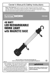
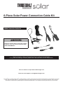
6-Piece Solar Power Connection Cable Kit
68684 Connection Cable Kit
Read this material before using this product.
Failure to do so can result in serious injury.
SAVE THIS MANUAL.
When unpacking, make sure that the product is intact and undamaged.
If any parts are missing or broken, please call 1-800-444-3353 as soon as possible.
Visit our website at: http://www.harborfreight.com
Email our tech support at: [email protected]
Copyright© 2011 by Harbor Freight Tools®. All rights reserved. No portion of this manual or any artwork contained herein may be reproduced in any shape
or form without the express written consent of Harbor Freight Tools. Diagrams within this manual may not be drawn proportionally. Due to continuing
improvements, actual product may differ slightly from the product described herein. Tools required for assembly and service may not be included.
IMPORTANT SAFETY
INFORMATION
In this manual, on the labeling, and all other
information provided with this product:
This is the safety alert symbol. It is
used to alert you to potential personal
injury hazards. Obey all safety
messages that follow this symbol
to avoid possible injury or death.
DANGER indicates a hazardous situation which, if
not avoided, will result in death or serious injury.
WARNING indicates a hazardous situation which, if
not avoided, could result in death or serious injury.
CAUTION, used with the safety alert symbol,
indicates a hazardous situation which, if not
avoided, could result in minor or moderate injury.
Safety Precautions
1. Wear ANSI-approved safety goggles and heavyduty work gloves during installation. Do not
wear jewelry or metal watches when working
near solar panels, wiring or batteries.
2. Keep installation area clean and well lit.
3. Install out of reach of children.
4. Keep bystanders out of the area during installation.
5. Do not install when tired or when under
the influence of drugs or medication.
6. Use in 12 VDC systems only. Do not use to make
connections exceeding 300 volts or 4 amps.
SAVE THESE
INSTRUCTIONS.
Operation
IMPORTANT! Read the ENTIRE IMPORTANT
SAFETY INFORMATION section at the beginning of
this manual including all text under subheadings
therein before set up or use of this product:
Note: For additional information regarding
the parts listed in the following pages, refer to
the Parts List near the end of this manual.
NOTICE is used to address practices
not related to personal injury.
Making Connections
CAUTION, without the safety alert symbol, is used to
address practices not related to personal injury.
WARNING Read all safety warnings and
instructions. Failure to follow the warnings and
instructions may result in electric shock, fire and/
or serious injury.
Save all warnings and instructions for
future reference. The warnings, precautions,
and instructions discussed in this instruction
manual cannot cover all possible conditions and
situations that may occur. It must be understood
by the operator that common sense and caution
are factors which cannot be built into this
product, but must be supplied by the operator.
1. When using the Battery Clamp (1), the Red (positive)
clamp should be connected to the positive battery
terminal and the Black (negative) clamp should
be connected to the negative battery terminal.
2. Please note that “+” stands for positive pole and
“-” stands for the negative terminal. WARNING!
Follow indicated polarity for all connections and
verify all connections are secure before use.
3. When disconnecting Battery Clamp, disconnect
the positive connection before disconnecting the
negative connection. WARNING! Do not disconnect
battery before disconnecting solar panel.
4. The Dual Extension Connector (2) can be used in
case the lead wire of your Solar Panel or product is
not long enough. Connect the Extension to the lead
wire and the solar product. NOTE: A longer lead
wire may reduce the amount of electricity coming
from the Solar Panel to the item being charged.
5. The Lighter Plugs (3,4) and 12V Adapter (5)
can be used to connect the solar products
to various charge controller terminals.
6. The Charge Indicator (6) is used to determine if
the solar charger/solar power kit is functioning
Page 2
For technical questions, please call 1-800-444-3353.
SKU 68684
(has sufficient electricity) or not. Attach the Charge
Indicator to the solar product’s lead wire. The LED
light will blink if there is sufficient power. NOTE:
Solar chargers/solar power kits will function
only when exposed under direct sunlight.
Wiring
Note: Only a licensed electrician and a licensed building
contractor can safely design and implement a grid
tie-in system. Any grid tie-in system must meet all
applicable building and electrical codes, and must meet
standards established by the area power company.
1. Run wires from panels, through weatherproof
grommets and into enclosure where charge
controller/regulator is located. Use wires
of the proper size and rating and use twist
connectors (not included) to connect wires.
2. Secure all connections using terminals, or solder
all wire splices to ensure good connections.
3. Weatherproof all connections and route the wire in
a way that it will not be torn loose from the panel.
Servicing
Procedures not specifically explained in
this manual must be performed by a
qualified technician.
b. Disconnect solar panel after use.
c. Disconnect all batteries after use.
TO PREVENT SERIOUS INJURY FROM
ELECTRIC SHOCK OR CUTS:
Do not use damaged adapters.
If wiring insulation is damaged or
weathered, solar panel glass is cracked,
or housing is opened, have the problem corrected
before further use.
Cleaning
Clean and inspect all adapters and the Solar Power
system used with these adapters MONTHLY, or
more frequently to maintain peak efficiency.
1. Wear electrically insulated gloves and
ANSI-approved safety goggles. .
2. Inspect the general condition of the Solar Power
System, including panel, batteries, controllers,
and mounting connections. Check for loose
hardware, wiring insulation damage or weathering,
cracked glass, open housing, cracked or broken
parts, loose or corroded contacts, and any other
condition that may affect its safe operation.
3. Inspect and maintain batteries according
to supplier’s instructions.
TO PREVENT SERIOUS INJURY FROM ELECTRIC
SHOCK:
Before service, maintenance or cleaning:
a. Dry outdoor wiring thoroughly while
wearing electrically insulated gloves.
Limited 90 Day Warranty
Harbor Freight Tools Co. makes every effort to assure that its products meet high quality and durability standards,
and warrants to the original purchaser that this product is free from defects in materials and workmanship for the
period of 90 days from the date of purchase. This warranty does not apply to damage due directly or indirectly,
to misuse, abuse, negligence or accidents, repairs or alterations outside our facilities, criminal activity, improper
installation, normal wear and tear, or to lack of maintenance. We shall in no event be liable for death, injuries
to persons or property, or for incidental, contingent, special or consequential damages arising from the use of
our product. Some states do not allow the exclusion or limitation of incidental or consequential damages, so the
above limitation of exclusion may not apply to you. THIS WARRANTY IS EXPRESSLY IN LIEU OF ALL OTHER
WARRANTIES, EXPRESS OR IMPLIED, INCLUDING THE WARRANTIES OF MERCHANTABILITY AND FITNESS.
To take advantage of this warranty, the product or part must be returned to us with transportation charges
prepaid. Proof of purchase date and an explanation of the complaint must accompany the merchandise.
If our inspection verifies the defect, we will either repair or replace the product at our election or we may
elect to refund the purchase price if we cannot readily and quickly provide you with a replacement. We will
return repaired products at our expense, but if we determine there is no defect, or that the defect resulted
from causes not within the scope of our warranty, then you must bear the cost of returning the product.
This warranty gives you specific legal rights and you may also have other rights which vary from state to state.
SKU 68684
For technical questions, please call 1-800-444-3353.
Page 3
PLEASE READ THE FOLLOWING CAREFULLY
THE MANUFACTURER AND/OR DISTRIBUTOR HAS PROVIDED THE PARTS LIST AND ASSEMBLY DIAGRAM
IN THIS MANUAL AS A REFERENCE TOOL ONLY. NEITHER THE MANUFACTURER OR DISTRIBUTOR
MAKES ANY REPRESENTATION OR WARRANTY OF ANY KIND TO THE BUYER THAT HE OR SHE IS
QUALIFIED TO MAKE ANY REPAIRS TO THE PRODUCT, OR THAT HE OR SHE IS QUALIFIED TO REPLACE
ANY PARTS OF THE PRODUCT. IN FACT, THE MANUFACTURER AND/OR DISTRIBUTOR EXPRESSLY
STATES THAT ALL REPAIRS AND PARTS REPLACEMENTS SHOULD BE UNDERTAKEN BY CERTIFIED AND
LICENSED TECHNICIANS, AND NOT BY THE BUYER. THE BUYER ASSUMES ALL RISK AND LIABILITY
ARISING OUT OF HIS OR HER REPAIRS TO THE ORIGINAL PRODUCT OR REPLACEMENT PARTS
THERETO, OR ARISING OUT OF HIS OR HER INSTALLATION OF REPLACEMENT PARTS THERETO.
Parts List and Diagrams
Part
Description
Qty.
1
Battery Clamps
2
Dual Extension Connector
1
3
Male Cigarette Lighter Plug
1
4
Female Cigarette Lighter Plug
1
5
12V Adapter
1
6
LED Charge Indicator
1
Record Product’s Serial Number Here:
Note: If product has no serial number, record month and year of purchase instead.
Note: Some parts are listed and shown for illustration purposes only,
and are not available individually as replacement parts.
3491 Mission Oaks Blvd. • PO Box 6009 • Camarillo, CA 93011 • (800) 444-3353
1