1
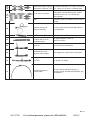
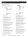
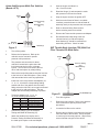
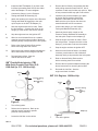
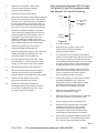
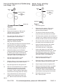
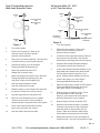
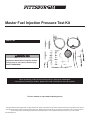
Master Fuel Injection Pressure Test Kit
Item 97706
Read this material before using this product.
Failure to do so can result in serious injury.
Save this manual.
When unpacking, make sure that the product is intact and undamaged.
If any parts are missing or broken, please call 1-800-444-3353 as soon as possible.
Visit our website at: http://www.harborfreight.com
Copyright© 2006 by Harbor Freight Tools®. All rights reserved. No portion of this manual or any artwork contained herein may be reproduced in any shape or
form without the express written consent of Harbor Freight Tools. Diagrams within this manual may not be drawn proportionally. Due to continuing improvements, actual product may differ slightly from the product described herein. Tools required for assembly and service may not be included.
Manual Revised 11c
not use damaged products. Tag damaged
products “Do not use” until repaired.
Product Specifications
Product
Features
Material
Contents
- Allows for accurate and quick diagnoses of fuel
intake issues.
- Compatible with most domestic and import cars.
- Includes all necessary adapter clamps and hoses.
- Quick, convenient hook ups.
Brass / Steel / Aluminum / Polyurethane / Rubber /
Vinyl / Thermoplastic
- Fuel Gauge w/Quick Release Valve
- Seven Various Hose Assemblies
- Four Metric Paired Hose Adapters
- Two Steel Hose Clamps
- Four Copper Washers
- Fifteen Metric Sized Fittings
- 8 SAE Sized Fittings
- Case
Save This Manual
You will need this manual for the safety warnings and
precautions, assembly, operating, inspection, maintenance
and cleaning procedures, parts list and assembly diagram.
Keep your invoice with this manual. Write the invoice
number on the inside of the front cover. Keep this manual
and invoice in a safe and dry place for future reference.
General Safety Warnings
WARNING Read all safety warnings and
instructions. Failure to follow the warnings and
instructions may result in electric shock, fire and/
or serious injury.
Save all warnings and instructions
for future reference.
1.
Keep your work area clean and well lit.
Cluttered and dark work areas invite accidents.
2.
Stay alert. Watch what you are doing, and
use common sense when operating tools
and equipment. Do not assemble or use this
product while tired or under the influence of
drugs, alcohol, or medication. A moment of
inattention while operating tools and equipment
may result in serious personal injury.
3.
4.
5.
REV 11c
Wear eye protection. Wear ANSIapproved safety impact glasses and full
face shield when using this product.
Do not force the Pressure Test Kit. Use
the correct product for your application. The
correct product will do the job better and
safer at the rate for which it is designed.
Maintain the Pressure Test Kit with care.
Keep this product clean. Properly maintained
products are less likely to malfunction. Do
SKU 97706
6.
Check for any condition that may negatively
affect the Pressure Test Kit’s operation. If
readings are inconsistent, or if it appears that
the fuel gauge is not functioning properly,
the Test Kit should be serviced by a qualified
service technician. Many accidents are
caused by poorly maintained products.
7.
Use only accessories that are recommended by
the manufacturer for your model. Accessories
that may be suitable for one product may become
hazardous when used on another product.
8.
Industrial applications must follow
OSHA requirements.
9.
Maintain labels and nameplates on the
Pressure Test Kit. These carry important
information. If unreadable or missing, contact
Harbor Freight Tools for a replacement.
10.
Use the right product for the job. There are
certain applications for which this product was
designed. Do not use small products to do the
work of larger industrial products. Do not use this
product for a purpose for which it was not intended.
11.
Product service must be performed only
by qualified service technician. Service
or maintenance performed by unqualified
personnel could result in a risk of injury.
12.
When servicing the Pressure Test Kit, use
only identical replacement parts. Follow
instructions in the “Inspection, Maintenance,
And Cleaning” section of this manual. Use of
unauthorized parts or failure to follow maintenance
instructions may create a risk of personal injury.
13.
Always make sure the area of use for this
product is clear of any children. Do not
allow children to play with this product.
14.
Do not allow the vehicle’s engine to run while
using the Pressure Test Kit. When running, the
engine of a vehicle produces carbon monoxide, a
colorless, odorless, toxic gas that, when inhaled,
can cause serious personal injury or death.
15.
Prior to using this product, make sure
to read and understand all instructions
and safety precautions as outlined in
the vehicle manufacturer’s manual.
16.
Always keep hands and fingers away from
the moving parts and hot parts of an engine.
For technical questions, please call 1-800-444-3353.
PAGE 2
17.
Do not use this Pressure Test
Kit on diesel fuel systems.
18.
Do not smoke while performing any
fuel injection tests or repairs.
19.
Always have a dry chemical (Class
B) fire extinguisher within reach.
20.
Make sure to provide a suitable container to
catch released fuel when the system
is de-pressurized.
21.
Take extra care to prevent fuel from contacting
hot engine parts. It is recommended that
tests be performed when the engine is cold.
22.
If a drop light is used, do not allow fuel
to contact the hot surface of the bulb.
23.
Never remove any fittings with
the engine running.
24.
Never loosen any fittings or attempt to remove
hoses of vehicle or Pressure Test Kit until you
have relieved the fuel system pressure. Refer
to the vehicle manufacturer’s service manual
for specific fuel pressure relief procedures.
25.
Always check all connections for leaks
during the testing procedure. At any sign
of leaks, turn off the engine or disable the
fuel pump. Clean up any spilled fuel and
repair all leaks before resuming test.
26.
When preparing for pressure testing,
make sure the vehicle’s transmission is
placed in “PARK” or “NEUTRAL” and
the emergency brake is applied.
27.
When the test is complete, de-pressurize
the system and remove the Pressure Test
Kit. Re-assemble the vehicle’s fuel line(s) to its
original condition. Start the engine and check for
leaks. If any leaks are present, stop the engine,
relieve fuel pressure and repair all leaks.
28.
WARNING: The brass components of this
product contain lead, a chemical known to
the State of California to cause birth defects
(or other reproductive harm). (California
Health & Safety code § 25249.5, et seq.)
29.
People with pacemakers should consult their
physician(s) before use. Electromagnetic fields in
close proximity to heart pacemaker could cause
pacemaker interference or pacemaker failure.
Caution is necessary when near coil, spark plug
cables, or distributor of running engine. Engine
should be off during distributor adjustment.
30.
The warnings and cautions discussed in this
manual cannot cover all possible conditions and
situations that may occur. It must be understood
by the operator that common sense and caution
are factors which cannot be built into this
product, but must be supplied by the operator.
Save these instructions.
REV 11c
SKU 97706
For technical questions, please call 1-800-444-3353.
PAGE 3
Applications
#
Picture
Description
Application
1
Basic Gauge with Boot
and Hook - 100 PSI
2
For vehicles with quick connect fuel filters such
General Motors® 2.5L & 5.7L
as 2.5L Oldsmobile® Ciera 1989 & up, and 5.7L
(Non Multi-Port)
Chevrolet® Caprice 1991 & up.
3
General Motors® 2.2L
(Non Multi-Port)
1992 & up: Chevrolet® Cavalier, Pontiac®
Sunbird, Buick® Skylark, and Quad 4 equipped
Pontiac® Grand Am.
4
Hose Clamps and
Connection Hoses
For use in making certain hook up connections.
5
General Motors® Throttle
Body Injection (TBI)
Inline Adapter - Replaces fuel filter with threads
on both ends.
6
Parts
Seals, Tank Valve, and Gasket.
7
Double End Barbed Hose
Adapter
When vehicles require testing by splicing into
1/4", 5/16", or 3/8" fuel line hose.
Single End Barbed Hose
Adapter
Honda®, Acura® & Sterling®
Multi-Port (PGM-FI)
All vehicles requiring end of line testing with
1/4", 5/16", or 3/8" fuel line hose.
8
9
Connects to #8 for basic testing.
For vehicles with 6mm-1.00 fittings.
REV 11c
SKU 97706
For technical questions, please call 1-800-444-3353.
PAGE 4
10
Asian and European vehicles For vehicles with 8mm-1.00, 10mm-1.00, 2mmwith Multi-Port & Bosch® AFC 1.25, 12mm-1.50, & 14mm-1.50 Banjo Bolts.
thru
14
E & K Jetronic® Systems
15
thru
24
CISE
Test CIS (Continuous Injection Systems) found
on European cars and Volkswagon® models
assembled in the U.S. For vehicles with
metric threads.
Test CISE (Constant Injection System
Electronic) found on European cars with metric
threads.
Pressure Testing and
Bleed-off Assembly
For use in performing tests with Basic Gauge
(1) and Adapters.
Ford® Multi-Port (EFI)
General Motors®, Chrysler®
& Imports with 7/16”-20
threaded test port
For smaller Schrader® valves.
28
Ford® CFI
For 5/16" hair pin connections.
29
General Motors® and
Chrysler® Inline Adapter
Inline Adapter for vehicles with 3/8” hair pins.
30
Ford® EFI
For Spring Lock fittings.
31
CIS Testing Assembly
with Ball Valve
For use in testing with Basic Gauge (1),
Pressure Testing, and Bleed-off Assembly (25)
and Adapters.
25
26
27
For larger Schrader® valves on
Multi-Port vehicles.
REV 11c
SKU 97706
For technical questions, please call 1-800-444-3353.
PAGE 5
Typical Hook-Ups
Note: Prior to using this product, make sure to read and
understand all instructions and safety precautions as outlined
in the vehicle manufacturer’s manual.
Ford® Multi-Port (EFI):
Gauge
(1)
GM Multi-Port and Chrysler Multi-Port:
®
®
Pressure Testing
And
Bleed-Off Assy.
(25)
Gauge
(1)
Pressure Testing
And
Bleed-Off Assy.
(25)
Ford® Adapter
(26)
GM®/Chrysler®
Adapter (27)
Figure A
Figure B
1.
Turn off the ignition.
1.
Turn off the ignition.
2.
2.
Relieve the fuel pressure. Refer to the
vehicle’s service manual for specific
pressure relief procedures.
Relieve the fuel pressure. Refer to the
vehicle’s service manual for specific
pressure relief procedures.
3.
If the vehicle has multi-port fuel injection, the
test valve is located on the fuel rail. Remove
the protective cap from the test valve.
4.
Connect the Gauge (1) to the Pressure
Testing and Bleed-off Assembly (25).
5.
Attach the female end of Ford® Adapter
(26) to test the valve. Hand tighten.
6.
Attach the female quick coupler on the Pressure
Testing and Bleed-off Assembly (25) to the male
quick coupler on the Ford® Adapter (26).
7.
Start the engine and allow it to
idle. Check for leaks.
8.
Read the Gauge (1) and compare result
with pressure in service manual.
9.
Stop the engine and turn the ignition OFF.
10.
With free end of bleed-off hose in suitable
container, press the button on side of bleed-off
assembly slowly to de-pressurize the fuel system.
11.
Refer to the General Safety Rules section
before removing the tester from the vehicle.
12.
Replace the protective cap onto test
fitting on vehicle. Check for leaks.
3.
4.
Connect the Gauge (1) to the Pressure
Testing and Bleed-off Assembly (25).
Remove the protective cap from
test fitting on vehicle.
5.
Attach the swivel female fitting on the Adapter (27)
to the test fitting on the vehicle. Hand tighten.
6.
Attach the female quick coupler on the Pressure
Testing and Bleed-off Assembly (25) to the
male quick connector on the Adapter (27).
7.
Start the engine and allow it to
idle. Check for leaks.
8.
Read the Gauge (1) and compare the result
with the pressure in service manual.
9.
Stop engine and turn ignition OFF.
10.
With free end of Bleed-off Hose in suitable
container, press the Button on side of bleed-off
assembly slowly to de-pressurize the fuel system.
11.
12.
Refer to the General Safety Rules section
before removing Tester from vehicle.
Replace the protective cap onto the test
fitting on vehicle. Check for leaks.
REV 07f, 07i, 11c
SKU 97706
For technical questions, please call 1-800-444-3353.
PAGE 6
Asian And European Multi-Port Vehicles
(Bosch® AFC):
Gauge
(1)
Pressure Testing
And
Bleed-Off Assy.
(25)
9.
Start the engine and allow it to
idle. Check for leaks.
10.
Read the Gauge (1) and compare the result
with pressure in the service manual.
11.
Stop the engine and turn the ignition OFF.
12.
With free end of bleed-off hose in a suitable
container, press the button on side of bleed-off
assembly slowly to de-pressurize the fuel system.
13.
Refer to General Safety Rules section
before removing tester from vehicle.
14.
Remove the Tester and the pressure test Adapter.
15.
Re-assemble the banjo fitting to the fuel
inlet and fuel rail (or cold start injector).
New Gaskets (6) should be used when reassembling fuel lines. Check for leaks.
Adapters
(10, 11, 12, 13, 14)
Gaskets (6)
Figure C
1.
Turn off the ignition.
2.
Relieve the fuel pressure. Refer to the
vehicle’s service manual for specific
pressure relief procedures.
3.
The pressure test connection for these
vehicles is located at the point where the
fuel inlet meets the fuel rail or cold start
injector. The fuel inlet is secured to the fuel
rail of cold start injector by a banjo fitting.
4.
Remove the banjo fitting that secures the fuel inlet
to the fuel rail or cold start injector. Place a shop
cloth around the bolt to catch any spilled fuel.
5.
Install one of the five pressure test Adapters (10,
11, 12, 13, 14) with the corresponding sealing
washer and one of the gaskets from the banjo
fitting so that the fuel inlet is once again connected
to the fuel rail or cold start injector. The test
Adapter will hold the banjo assembly in position.
6.
Torque the Adapters (10, 11, 12, 13,
14) to the following specifications:
Adapter #
10
11
12
13
14
Size
8mm-1.00
10mm-1.00
12mm-1.25
12mm-1.50
14mm-1.50
Torque Specifications
48 In./Lb. (5.5 N-m)
72 In./Lb. (8.0 N-m)
96 In./Lb. (11.0 N-m)
96 In./Lb. (11.0 N-m)
125 In./Lb. (14.0 N-m)
7.
Connect the Gauge (1) to the Pressure
Testing and Bleed-off Assembly (25).
8.
Attach the female quick coupler on the
Pressure Testing and Bleed-off Assembly to
the male quick coupler on the test Adapter.
GM® Throttle Body Injection (TBI) With Fuel
Filter Threaded On Both Sides:
Gauge
(1)
Pressure Testing
And
Bleed-Off Assy.
(25)
Figure D
Gm TBI Adapter (5)
1.
Turn off the ignition.
2.
Relieve the fuel pressure. Refer to the vehicle’s
service manual for specific pressure relief
procedures.
3.
Locate the fuel filter on the vehicle.
4.
Remove the fuel filter by unscrewing the fuel lines
from both ends of the fuel filter. Use a container
to catch any fuel that may spill out. Wipe off any
excess fuel that may spill on the vehicle.
REV 11c
SKU 97706
For technical questions, please call 1-800-444-3353.
PAGE 7
5.
Install the GM® TBI Adapter (5) in place of the
fuel filter by threading each fuel line into either
end of the Adapter. Do not overtighten.
6.
Connect the Gauge (1) to the Pressure
Testing and Bleed-off Assembly (25).
7.
Attach the female quick coupler on the Pressure
Testing and Bleed-off Assembly to the male
quick coupler on the GM® TBI Adapter (5).
8.
Start the engine and check for leaks. Read
the fuel pressure. Compare the value on the
Gauge (1) to the value in the service manual.
9.
Stop the engine and turn the ignition OFF.
10.
With free end of bleed-off hose in a suitable
container, press the button on side of bleed-off
assembly slowly to de-pressurize the fuel system.
11.
Refer to the General Safety Rules section
before removing tester from vehicle.
12.
Remove the fuel pressure Adapter following the
above instructions for removing the fuel filter.
13.
Re-install the fuel filter. Start the
vehicle and check for leaks.
GM® Throttle Body Injection (TBI)
With Quick Connect Fuel Filter (2.5L
1989 And Up, 5.7L 1991 And Up):
Gauge
(1)
4.
Remove the fuel filter by compressing the tabs
while pulling outward on each fuel line. Use a
container to catch any fuel that may spill out. Wipe
off any excess fuel that may spill on the vehicle.
5.
Install the fuel pressure Adapter (2) in place
of the fuel filter by pushing each of the
Adapter’s male tubes into the fuel lines.
Make sure the nylon clips on the tubes are
seated inside the fuel line connectors.
6.
Connect the Gauge (1) to the Pressure
Testing and Bleed-off Assembly (25).
7.
Attach the female quick coupler on the
Pressure Testing and Bleed-off Assembly to
the male quick coupler on the Adapter (2).
8.
Start the engine and check for leaks. Read
the fuel pressure. Compare the value on the
Gauge (1) to the value in the service manual.
9.
Stop the engine and turn the ignition OFF.
10.
With free end of bleed-off hose in a suitable
container, press button on side of bleed-off
assembly slowly to de-pressurize the fuel system.
11.
Refer to General Safety Rules section
before removing tester from vehicle.
12.
Remove the fuel pressure Adapter following the
above instructions for removing the fuel filter.
13.
Re-install the fuel filter. Start the
engine and check for leaks.
GM® 2.2L Engines, 1992 And Up:
Pressure Testing
And
Bleed-Off Assy.
(25)
Gauge
(1)
Pressure Testing
And
Bleed-Off Assy.
(25)
Adapter
(2)
Figure E
1.
Turn off the ignition.
2.
Relieve the fuel pressure. Refer to the
vehicle’s service manual for specific
pressure relief procedures.
3.
Locate the fuel filter on the vehicle.
Adapter (3)
Figure F
1.
Turn off the ignition.
REV 11c
SKU 97706
For technical questions, please call 1-800-444-3353.
PAGE 8
2.
Relieve the fuel pressure. Refer to the
vehicle’s service manual for specific
pressure relief procedures.
3.
Locate the fuel filter on the vehicle.
4.
Remove the fuel filter by unscrewing the steel fuel
line from one end of the fuel filter. Remove the
nylon fuel line on the other end by compressing
the tabs while pulling outward on the fuel line.
Use a container to catch any fuel that may spill
out. Wipe off any excess fuel that may spill out.
5.
Install the fuel pressure Adapter (3) in place
of the fuel filter by threading the steel fuel line
into the threaded end of the Adapter. Do not
overtighten. Connect the other end of the
Adapter by pushing the male tube into the
nylon fuel line. Make sure the nylon clip on the
tube is seated inside the fuel line connector.
6.
Connect the Gauge (1) to the Pressure
Testing and Bleed-off Assembly (25).
7.
Attach the female quick coupler on the Pressure
Testing and Bleed-off Assembly (25) to the
male quick coupler on the Adapter (3).
8.
Start the engine and check for leaks. Read
the fuel pressure. Compare the value on the
Gauge (1) to the value in the service manual.
9.
Stop the engine and turn the ignition OFF.
10.
With free end of bleed-off hose in a suitable
container, press button on side of bleed-off
assembly slowly to de-pressurize the fuel system.
11.
Refer to General Safety Rules section
before removing tester from vehicle.
12.
Remove the fuel pressure Adapter (3)
following the above instructions for removing
the fuel filter. Re-install the fuel filter. Start
the engine and check for leaks.
Ford® Central Fuel Injection (CFI) 1.9L And
2.3L With 5/16” Hair Pin Coupling And GM®
And Chrysler® 3/8” Hair Pin Coupling:
Gauge
(1)
Pressure Testing
And
Bleed-Off Assy.
(25)
Adapter
(28 Or 29)
Figure G
1.
Turn off the ignition.
2.
Relieve the fuel pressure. Refer to the
vehicle’s service manual for specific
pressure relief procedures.
3.
The connection with the vehicle’s fuel injection
system is at the throttle body. Remove the fuel line
at the inlet by prying up on the hair pin from the
coupling with a small screwdriver. Use care as the
hair pin is made of plastic. Once disconnected,
re-install the hair pin into the hair pin coupling.
4.
Attach the Hair Pin Adapter (28 for Ford® and
29 for GM® and Chrysler®) to the disconnected
fuel line. Make sure both ends of mating
parts are seated and locked together.
5.
Connect the Gauge (1) to the Pressure Testing
and Bleed-off Assembly (25). Attach the
female quick coupler on the Pressure Testing
and Bleed-off Assembly (25) to the male
quick coupler on the Adapter (28 or 29).
6.
Start the engine and allow it to idle.
Check all connections for leaks.
7.
Read the Gauge (1) and compare the result with
the pressure values in the service manual.
8.
Stop the engine and turn the ignition OFF.
9.
With free end of bleed-off hose in a suitable
container, press button on side of bleedoff assembly slowly to de-pressurize the
fuel system. Refer to General Safety Rules
section before removing tester from vehicle.
10.
Remove the fuel pressure Adapter following the
above instructions. Re-install the vehicle’s fuel
line. Start the engine and check for leaks.
REV 11c
SKU 97706
For technical questions, please call 1-800-444-3353.
PAGE 9
Ford® Central Fuel Injection (CFI) With Spring
Lock Fittings - 2.5L:
Honda®, Acura®, & Sterling®
Multi-Port (PGM-FI):
Gauge
(1)
Gauge
(1)
Pressure Testing
And
Bleed-Off Assy.
(25)
Pressure Testing
And
Bleed-Off Assy.
(25)
Adapter (9)
Figure I
Adapter (30)
Figure H
1.
Turn off the ignition.
2.
Relieve the fuel pressure. Refer to the
vehicle’s service manual for specific
pressure relief procedures.
3.
The connection with the vehicle’s fuel
injection system is on the fuel rail.
4.
A disconnect tool (not included) is
required to separate the spring lock
fitting on the vehicle’s fuel line.
5.
After the spring lock fitting has been disconnected,
assemble the Ford® Spring Lock Adapter
(30) into the line, making sure both ends of
the mating couplings are locked together.
6.
Connect the Gauge (1) to the Pressure
Testing and Bleed-off Assembly (25). Attach
the female quick coupler on the Pressure
Testing and Bleed-off Assembly (25) to the
male quick coupler on the Adapter (30).
7.
Start the engine and allow it to idle.
Check all connections for leaks.
8.
Read the Gauge (1) and compare the result with
the pressure values in the service manual.
9.
Stop the engine and turn the ignition OFF.
10.
With free end of bleed-off hose in a suitable
container, press button on side of bleedoff assembly slowly to de-pressurize the
fuel system. Refer to General Safety Rules
section before removing tester from vehicle.
11.
Using a disconnect tool, remove the test
Adapter (30) and install the vehicle’s fuel
line. Start the vehicle and check for leaks.
1.
Turn off the ignition.
2.
Relieve the fuel pressure. Refer to the
vehicle’s service manual for specific
pressure relief procedures.
3.
The test port is at the vehicle’s fuel filter,
under the hood, just forward of the firewall.
4.
The Fuel outlet is secured to the fuel filter by a
“double D” bolt. Within this bolt is a smaller hex
bolt that provides access to the test connection.
5.
Place a shop cloth around the fuel outlet
and slowly remove the smaller hex bolt.
6.
Screw the small male end of the Honda®
Adapter (9) into the hole where the
removed hex bolt was. Hand tighten.
7.
Connect the Gauge (1) to the Pressure
Testing and Bleed-off Assembly (25). Attach
the female quick coupler on the Pressure
Testing and Bleed-off Assembly (25) to the
male quick coupler on the Adapter (9).
8.
Start the engine and allow it to idle.
Check all connections for leaks.
9.
Read the Gauge (1) and compare the result with
the pressure values in the service manual.
10.
Stop the engine and turn the ignition OFF.
11.
With free end of bleed-off hose in a suitable
container, press button on side of bleedoff assembly slowly to de-pressurize the
fuel system. Refer to General Safety Rules
section before removing tester from vehicle.
12.
Re-install the hex bolt on the fuel
filter. Check for leaks.
REV 11c
SKU 97706
For technical questions, please call 1-800-444-3353.
PAGE 10
Ford® Throttle Body Injection
With Small Schrader® Valve:
All Vehicles With 1/4”, 5/16”,
or 3/8” Fuel Line Hose:
Gauge
(1)
Gauge
(1)
Pressure Testing
And
Bleed-Off Assy.
(25)
Pressure Testing
And
Bleed-Off Assy.
(25)
Adapter
(7)
To Inlet Fuel
Line Hose
Adapter
(26)
Figure K
Figure J
1.
Turn off the ignition.
Hose & Hose Clamps
(4)
To Throttle Body
Inlet
Or
Discharge Side Of
Fuel Pump
1.
Turn off the ignition.
2.
2.
Relieve the fuel pressure. Refer to the
vehicle’s service manual for specific
pressure relief procedures.
Relieve the fuel pressure. Refer to the
vehicle’s service manual for specific
pressure relief procedures.
3.
Loosen the hose clamp and disconnect the fuel
line hose from the inlet side of the vehicle’s
throttle body or discharge side of the fuel pump.
4.
Assemble the Double End Barbed Adapter
(7) and Hose (4) with Hose Clamps (4).
5.
Connect the Double End Barbed Adapter (7) as
assembled above between the disconnected
fuel line and the throttle body inlet or fuel
pump. Tighten all Hose Clamps (4) securely.
6.
Connect the Gauge (1) to the Pressure
Testing and Bleed-off Assembly (25).
7.
Attach the female quick coupler on the Pressure
Testing and Bleed-off Assembly (25) to the
male quick coupler on the Adapter (7).
8.
Start the engine and allow it to idle. Check
all connections for leaks. Read the
Gauge (1) and compare the result with the
pressure values in the service manual.
9.
Stop the engine and turn the ignition OFF.
10.
With free end of bleed-off hose in a suitable
container, press button on side of bleed-off
assembly slowly to de-pressurize the fuel
system. Refer to the General Safety Rules
section before removing tester from vehicle.
11.
Replace the vehicle’s fuel line and tighten all
clamps securely. Check all connections for leaks.
3.
Remove the air cleaner assembly. The test valve
is located at the top of the throttle body unit.
4.
Connect the Gauge (1) to the Pressure
Testing and Bleed-off Assembly (25).
5.
Attach the female end of the Ford®
Adapter (26) to the test valve.
6.
Attach the female quick coupler on the Pressure
Testing and Bleed-off Assembly (25) to the
male quick coupler on the Adapter (26).
7.
Start the engine and allow it to idle.
Check all connections for leaks.
8.
Read the Gauge (1) and compare the result with
the pressure values in the service manual.
9.
Stop the engine and turn the ignition OFF.
10.
With free end of bleed-off hose in a suitable
container, press button on side of bleed-off
assembly slowly to de-pressurize the fuel system.
11.
Refer to the General Safety Rules section
before removing tester from vehicle.
12.
Start the vehicle and check for leaks.
REV 11c
SKU 97706
For technical questions, please call 1-800-444-3353.
PAGE 11
All Vehicles Requiring End Of Line Testing
With 1/4”, 5/16”, Or 3/8” Fuel Line Hose:
Chrysler® Throttle Body Injection:
Gauge
(1)
Gauge
(1)
Pressure Testing
And
Bleed-Off Assy.
(25)
Pressure Testing
And
Bleed-Off Assy.
(25)
Adapter
(7)
Hose & Hose
Clamps
(4)
To Inlet
Fuel Line
Hose
To Throttle
Body Inlet
Nipple
Figure M
Adapter
(8)
1.
Turn off the ignition.
2.
Relieve the fuel pressure. Refer to the
vehicle’s service manual for specific
pressure relief procedures.
Figure L
1.
Turn off the ignition.
3.
2.
Relieve the fuel pressure. Refer to the
vehicle’s service manual for specific
pressure relief procedures.
Loosen the hose clamp and disconnect
the fuel line hose from the inlet side
of the vehicle’s throttle body.
4.
3.
Loosen the hose clamp and
disconnect the fuel line.
Confirm if the size of the inlet fuel
line hose is 1/4" or 5/16".
5.
4.
Install the Single End Barbed Hose Adapter (8) into
the fuel supply hose. Tighten hose clamp securely.
Assemble the correct Hose (4) and Hose Clamps
(4) onto the Double End Barbed Adapter (7).
6.
5.
Connect the Gauge (1) to the Pressure
Testing and Bleed-off Assembly (25).
Connect the Adapter assembly between
the disconnected fuel line and the throttle
body inlet nipple on the vehicle. Tighten
all Hose Clamps (4) securely.
6.
Attach the female quick coupler on the Pressure
Testing and Bleed-off Assembly (25) to the
male quick coupler on the Adapter (8).
7.
7.
Start the engine and allow it to idle. Check
all connections for leaks. Read the
Gauge (1) and compare the result with the
pressure values in the service manual.
Connect the Gauge (1) to the Pressure
Testing and Bleed-off Assembly (25). Attach
the female quick coupler on the Pressure
Testing and Bleed-off Assembly (25) to the
male quick coupler on the Adapter (7).
8.
Start the engine and allow it to idle. Check
all connections for leaks. Read the
Gauge (1) and compare the result with the
pressure values in the service manual.
9.
Stop the engine and turn the ignition OFF.
10.
With free end of bleed-off hose in a suitable
container, press button on side of bleed-off
assembly slowly to de-pressurize the fuel
system. Refer to the General Safety Rules
section before removing tester from vehicle.
11.
Reconnect vehicle’s fuel line and tighten all clamps
securely. Check all connections for leaks.
8.
Stop the engine and turn the ignition OFF.
9.
With free end of bleed-off hose in a suitable
container, press button on side of bleed-off
assembly slowly to de-pressurize the fuel
system. Refer to the General Safety Rules
section before removing tester from vehicle.
10.
Reconnect vehicle’s fuel line and tighten all clamps
securely. Check all connections for leaks.
REV 11c
SKU 97706
For technical questions, please call 1-800-444-3353.
PAGE 12
Bosch® Continuous Injection
System (CIS) Testing:
Gauge
(1)
Pressure
Testing
And
Bleed-Off
Assy.
(25)
Constant Injection System Electronic
(CISE) - European Vehicles:
Gauge
(1)
Adapters
(10, 11, 12, 13,
15, 16, 18, 19,
20, 21, 22, 23,
Or 24)
Pressure Testing
And
Bleed-Off Assy.
(25)
And
“O-Rings”
CIS Testing
Assembly
With
Ball Valve
(31)
Adapters
(10, 11, 12, 13, 15,
16, 18, 19, 20, 21,
22, 23, Or 24)
And
“O-Rings”
Figure N
1.
Turn off the ignition.
2.
Clean the top of the fuel distributor to keep
dirt from entering the fuel system.
3.
Relieve the fuel pressure. Refer to the
vehicle’s service manual for specific
pressure relief procedures.
4.
The CIS system has a primary circuit with
pressure regulated at the fuel distributor. This
is known as supply pressure, primary pressure,
or line pressure. The side of the tester without
the ball valve is connected to this circuit. The
other circuit is known as the control circuit. This
contains the control pressure regulator, known as
the warm-up compensator. The side of the test
with the ball valve is connected to this circuit.
5.
Connect the Gauge (1) to the Pressure
Testing and Bleed-off Assembly (25).
6.
Install Adapter(s) (10, 11, 12, 13, 15, 16,
18, 19, 20, 21, 22, 23, or 24) and “O-Ring”
to the engine as required. Hand tighten
only. Then connect Hoses to Adapters.
7.
Attach the female quick coupler on the Pressure
Testing and Bleed-off Assembly (1) to the male
quick coupler on the CIS Testing Assembly with
Ball Valve (31). With free end of bleed-off hose in a
suitable container, press button on side of bleed-off
assembly slowly to release any air in the test Hose.
8.
Refer to the General Safety Rules section
before removing tester from vehicle. Remove
tester and Adapters from vehicle. Reconnect
vehicle’s fuel injection lines to original condition.
Start the vehicle and check for leaks.
Figure O
1.
Turn off the ignition.
2.
Clean the top of the fuel distributor to keep
dirt from entering the fuel system.
3.
Relieve the fuel pressure. Refer to the
vehicle’s service manual for specific
pressure relief procedures.
4.
Connect the Gauge (1) to the Pressure
Testing and Bleed-off Assembly (25).
5.
Install Adapter(s) (10, 11, 12, 13, 15,
16, 18, 19, 20, 21, 22, 23, or 24) and
“O-Ring” to the engine as required.
6.
Attach the female quick coupler on the
Pressure Testing and Bleed-off Assembly (1)
to the male quick coupler on the Adapter.
7.
Start the engine and allow it to idle.
Check for leaks. Read the fuel pressure.
Compare the value on the Gauge (1) to
the value in the service manual.
8.
With free end of bleed-off hose in a suitable
container, press button on side of bleed-off
assembly slowly to release any air in the test
Hose. Refer to the General Safety Rules
section before removing tester from vehicle.
9.
Remove tester and Adapter(s) from vehicle.
10.
Reconnect vehicle’s fuel injection
lines to original condition.
11.
Start vehicle and check for leaks.
REV 11c
SKU 97706
For technical questions, please call 1-800-444-3353.
PAGE 13
Inspection, Maintenance and Cleaning
1.
CAUTION! Make sure to wear ANSI-approved safety impact goggles before
performing any inspection, maintenance, or cleaning of Pressure Test Kit.
2.
Before each use: Inspect the general condition of the Pressure Test Kit. Check for damaged
parts, and any other condition that may affect this product’s safe operation. If a problem occurs,
have the problem corrected before further use. Do not use damaged equipment.
3.
To clean: Use a clean, soft, damp cloth and mild detergent. Then allow to air-dry. Do not use solvents.
4.
CAUTION! All maintenance, service, and repairs not discussed in this
manual should only be performed by a qualified service technician.
PLEASE READ THE FOLLOWING CAREFULLY
THE MANUFACTURER AND/OR DISTRIBUTOR HAS PROVIDED THE PARTS LIST AND ASSEMBLY DIAGRAM IN THIS MANUAL AS
A REFERENCE TOOL ONLY. NEITHER THE MANUFACTURER OR DISTRIBUTOR MAKES ANY REPRESENTATION OR WARRANTY
OF ANY KIND TO THE BUYER THAT HE OR SHE IS QUALIFIED TO REPLACE ANY PARTS OF THE PRODUCT. IN FACT, THE
MANUFACTURER AND/OR DISTRIBUTOR EXPRESSLY STATES THAT ALL REPAIRS AND PARTS REPLACEMENTS SHOULD BE
UNDERTAKEN BY CERTIFIED AND LICENSED TECHNICIANS, AND NOT BY THE BUYER. THE BUYER ASSUMES ALL RISKS
AND LIABILITY ARISING OUT OF HIS OR HER REPAIRS TO THE ORIGINAL PRODUCT OR REPLACEMENT PARTS THERETO, OR
ARISING OUT OF HIS OR HER INSTALLATION OF REPLACEMENT PARTS THERETO.
REV 11c
SKU 97706
For technical questions, please call 1-800-444-3353.
PAGE 14
Parts List And Assembly Diagram
Part
1
2
3
4
5
6
7
8
9
10
11
12
13
14
15
16
Description
0-100 PSI (0-7.0 Bar) Gauge w/Boot & Hang-Up Hook
GM® 2.5L & 5.7L Fuel Injection Pressure Test Adapter
GM® 2.2L Fuel Injection Pressure Test Adapter
Hose Clamps & Hoses
GM® Throttle Body Injection (TBI) Fuel Pressure
Adapter
Seals, Tank Valve & Gasket
Double End Barbed Hose Adapter
Single End Barbed Hose Adapter
6mm-1.00 Honda® & Acura® Multi-Port (PGM-FI)
Adapter
8mm-1.00 Banjo Bolt Adapter
10mm-1.00 Banjo Bolt Adapter
12mm-1.25 Banjo Bolt Adapter
12mm-1.50 Banjo Bolt Adapter
14mm-1.50 Banjo Bolt Adapter
8mm-1.00 Long Adapter
8mm-1.00 Female Adapter
Part
17
18
19
20
21
22
23
24
25
26
27
28
29
30
31
33
Description
8mm-1.00 Male Adapter w/O-Ring (1 Pieces)
8mm-1.00 Male Adapter (Long)
10mm-1.00 Female Adapter
10mm-1.00 Male Adapter
12mm-1.50 Female Swivel Adapter (2 Pieces)
14mm-1.50 Male & Female Swivel Adapter
1/4” BSPT Male & Female Swivel Adapter
16mm-1.50 Male & Female Swivel Adapter
Pressure Testing & Bleed-Off Assy.
Small Schrader® Valve Test Adapter for Ford®
Large Schrader® Valve Test Adapter for GM® &
Chrysler®
5/16” Hair Pin Adapter for Ford® CFI
3/8” Hair Pin Adapter for GM® & Chrysler®
Spring Lock Adapter for Ford® EFI
CIS Testing Assy. w/Ball Valve
Carrying Case (not shown)
33: CARRYING CASE NOT SHOWN.
3
1
2
18
9
10
19
11
20
12
8
25
21
13
14
15
4
6
5
7
16
22
23
17
24
26
27
31
28
29
30
NOTE:
Some parts are listed and shown for illustration purposes only,
and are not available individually as replacement parts.
SKU 97706
For technical questions, please call 1-800-444-3353.
REV 11c
PAGE 15
Limited 90 Day Warranty
Harbor Freight Tools Co. makes every effort to assure that its products meet high quality and durability
standards, and warrants to the original purchaser that this product is free from defects in materials and workmanship
for the period of 90 days from the date of purchase. This warranty does not apply to damage due directly or
indirectly, to misuse, abuse, negligence or accidents, repairs or alterations outside our facilities, criminal activity,
improper installation, normal wear and tear, or to lack of maintenance. We shall in no event be liable for death,
injuries to persons or property, or for incidental, contingent, special or consequential damages arising from the use
of our product. Some states do not allow the exclusion or limitation of incidental or consequential damages, so the
above limitation of exclusion may not apply to you. This warranty is expressly in lieu of all other
warranties, express or implied, including the warranties of merchantability and fitness.
To take advantage of this warranty, the product or part must be returned to us with transportation
charges prepaid. Proof of purchase date and an explanation of the complaint must accompany the merchandise.
If our inspection verifies the defect, we will either repair or replace the product at our election or we may
elect to refund the purchase price if we cannot readily and quickly provide you with a replacement. We will
return repaired products at our expense, but if we determine there is no defect, or that the defect resulted
from causes not within the scope of our warranty, then you must bear the cost of returning the product.
This warranty gives you specific legal rights and you may also have other rights which vary from state to state.
3491 Mission Oaks Blvd. • PO Box 6009 • Camarillo, CA 93011 • (800) 444-3353
REV 11c