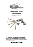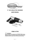
1
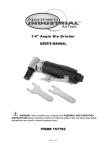
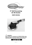
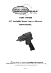
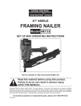
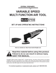
WARNING
Some dust created by power sanding, sawing, grinding, drilling, and other construction
activities contains chemicals known to the State of California to cause cancer, birth
defects or other reproductive harm. Some examples of these chemicals are:
lead from lead-based paints,
crystalline silica from bricks and cement and other masonry products, and
arsenic and chromium from chemically treated lumber.
Your risk from these exposures varies, depending on how often you do this type of work.
To reduce your exposure to these chemicals: work in a well-ventilated area, and work with
approved safety equipment, such as those dust masks that are specially designed to filter
out microscopic particles.
3/8in. BUTTERFLY IMPACT WRENCH
USER'S MANUAL
Distributed by
Northern Tool + Equipment Co., Inc.
2800 Southcross Drive West
Burnsville, MN 5337-0499
Made in China.
6 of 6
WARNING:
Read carefully and understand all INSTRUCTIONS before operating. Failure to follow
the safety rules and other basic safety precautions may result in serious personal injury.
Item# 139272
can damage the tool. You may have to use penetrating oil, heat, or a mechanical
wrench to remove the fastener.
13.When you are finished using this tool, turn off the air compressor and disconnect the
air hose. Put the Air Impact Wrench away in its proper storage place.
MAINTENANCE
1.Your Air Impact Wrench should be kept clean and dry.
2.When not in use, store your tool in a suitable place where it will not be exposed to water,
corrosive materials, or undue banging around.
3.If you are not using an in-line oiler, you should inject a few drops of pneumatic tool oil
into the air inlet of the tool and the oiler screw port after every hour of continuous use.
4.If your tool loses power, or you notice air leaks, take it to a certified technician for
service.
5.All repairs to this tool should be performed by a qualified service technician.
PART LIST
For technical questions and replacement parts, please call 1-800-222-5381.
TM
Thank you very much for choosing a Wel-Bilt , Product! For future reference, please
complete the owner's record below:
Model: _______________ Purchase Date: _______________
Save the receipt, warranty and these instructions. It is important that you read the entire
manual to become familiar with this product before using it.
This machine is designed for certain applications only. The distributor strongly
recommends that this machine is not modified and/or used for any application other than
that for which it was designed. If you have any questions relative to a particular
application, DO NOT use the machine until you have first contacted Northern Tool +
Equipment to determine if it can or should be performed on the product.
Before using this product, please read the following instructions carefully.
TECHNICAL SPECIFICATIONS
Part#
Description
Qty.
Part#
Description
Qty.
1
Housing
1
22
Back Cap
1
2
Oiler Screw
1
23
Spring
2
Item
Square Drive
Description
Item
Air Inlet Diameter
3/8in.
Free Speed
10,000 RPM
Min. Hose Size
Max. Torque
75 ft-lbs
Max. air pressure
Air Consumption
6 CFM
Description
1/4in.- 18NPT
3/8in.
90 PSI
3
Throttle Lever
1
24
Valve Seat
2
4
Anvil Bushing
1
25
O-ring
2
5
Socket Retaining Ring
1
26
Spring
2
6
O-ring
1
27
Plunger
2
7
Anvil
1
28
O-ring
2
8
Hammer Pin
1
29
O-ring
1
9
Hammer Cage
1
30
Air Inlet Block
1
10
Hammer Dog
1
31
Spring
1
11
Cam
1
32
Steel Ball
1
SAFETY WARNINGS
WARNING: When using tool, basic safety precautions should always be
2
1
33
Regulator
1
followed to reduce the risk of personal injury and damage to equipment.
34
Throttle Pin
2
35
Washer
1
12
Oil Seal
13
Ball Bearing
14
Front End Plate
1
15
Rotor Blade
6
36
Retainer Ring
1
16
Rotor
1
37
Spring Washer
4
17
Cylinder
1
38
Cap Screw
4
18
Rear End Plate
1
39
Rubber Nose Guard
1
19
Spring Pin
1
40
Retainer Plate
1
20
Ball Bearing
1
41
Screw
2
21
Back Cap Gasket
1
4 of 6
SAVE THIS MANUAL
You will need this manual for the safety warnings and precautions, assembly, operating,
inspection, maintenance and cleaning procedures, parts list and assembly diagram. Keep
this manual and invoice in a safe and dry place for future reference.
1.Keep work area clean. Cluttered areas invite injuries.
2.Observe work area conditions. Do not use machines or power tools in damp or wet
locations. Don't expose to rain. Keep work area well lit. Do not use electrically powered
tools in the presence of flammable gases or liquids.
3.Keep bystanders, pets and children away. Do not let unauthorized people handle
machines, tools, or extension cords.
4.Store idle equipment. When not in use, tools must be stored in a dry location to inhibit
rust. Always lock up tools and keep out of reach of children.
5.Use the right tool for the job. Do not attempt to force a small tool or attachment to do
the work of a larger industrial tool. There are certain applications for which this tool was
designed. It will do the job better and more safely at the rate for which it was intended. Do
not modify this tool and do not use this tool for a purpose for which it was not intended.
6.Dress properly while working. Do not wear loose clothing or jewelry as they can be
caught in moving parts. Protective, electrically non-conductive clothes and non-skid
footwear are recommended when working. Wear restrictive hair covering to contain long
hair.
7.Use eye, face and ear protection. Always wear ANSI-approved impact safety goggles.
Wear a full face shield if you are producing metal filings or wood chips. Wear an ANSIapproved dust mask or respirator when working around metal, wood, and chemical dusts
and mists. Wear ANSI-approved ear plugs.
8.Do not overreach. Keep proper footing and balance at all times. Do not reach over or
across running machines.
1 of 6
DIAGRAM
5 of 6
9.Maintain tools with care. Keep tools clean and in good condition for better and safer
performance. Follow instructions for lubricating and changing accessories. Inspect tool
fittings and hoses periodically and, if damaged, have them repaired by an authorized
technician. The handles must be kept clean, dry, and free from oil and grease at all times.
10.Disconnect power. Disconnect from air pressure source when not in use.
11.Remove adjusting keys and wrenches. Check that keys and adjusting wrenches are
removed from the tool or machine work surface before connecting it.
12.Avoid unintentional starting. Be sure the Butterfly Throttle Switch is in the neutral,
OFF position when not in use and before connecting to pressure source. Do not carry any
tool with your finger on the Butterfly Throttle Switch, whether it is attached or not.
13.Check for damaged parts. Before using any tool, any part that appears damaged
should be carefully checked to determine that it will operate properly and perform its
intended function. Check for alignment and binding of moving parts; any broken parts or
mounting fixtures; and any other condition that may affect proper operation. Any part that
is damaged should be properly repaired or replaced by a qualified technician. Do not use
the tool if the Butterfly Throttle Switch does not function properly.
14.Guard against electric shock when working on electrical equipment, such as
your air compressor. Prevent body contact with grounded surfaces such as pipes,
radiators, ranges, and refrigerator enclosures.
15.Replacement parts and accessories. When servicing, use only identical
replacement parts. Use of any other parts will void the warranty. Only use accessories
intended for use with this tool.
16.Do not operate tool if under the influence of alcohol or drugs, or if you are tired.
This may result in serious injury.
17.Use proper size and type air pressure line and fittings. The recommended air line
for this tool is 3/8" delivering no more than 90 PSI. Recommended air inlet size is 1/4" - 18
NPT.
18.Maintenance. For your safety, service and maintenance should be performed
regularly by a qualified technician.
19.You should maintain a proper regulator and moisture trap in your air line at all
times.
Note: Performance of this tool may vary depending on variations in local air pressure.
WARNING: The warnings, cautions, and instructions discussed in this instruction
manual cannot cover all possible conditions and situations that may occur. It must be
understood by the operator that common sense and caution are factors which cannot be
built into this product, but must be supplied by the operator.
WARNING: The brass components of this product contain lead, a chemical
known to the State of California to cause birth defects (or other reproductive harm).
(California Health & Safety code 25249.5, et seq.)
ASSEMBLY AND OPERATING INSTRUCTIONS
Fig. 1
2 of 6
1.Install a standard 1/4" Air Connector (not included) to the Air Inlet. First wrap the
threaded portion of the 1/4" air connector with pipe thread seal tape before threading it
into the Air Inlet. Tighten securely.
2.Attach a standard quick connector (not included) to your 3/8" air pressure source hose.
Then attach the air hose to the Air Impact Wrench.
NOTE: If you are not using an automatic in-line oiler, add a few drops of pneumatic oil to
the Air Inlet before attaching the air hose. Add a few more drops of oil after every hour of
continual use.
3.Set the air pressure regulator on your air compressor at 90 PSI.
WARNING: Do not exceed the recommended pressure of 90 PSI. Damage to your
tool and possible personal injury and/or property damage may result.
4.Check the air line and its connections for air leaks. Make note of these, and repair them
before using this tool.
NOTE: Turn off your air compressor and disconnect the air pressure hose before
changing sockets or making any adjustments to this tool. Severe injury or property
damage may otherwise result.
WARNING: This tool generates considerable torque when in use. Always hold the
tool with both hands when using, and brace yourself to resist the torque which will be
delivered to the workpiece.
5.Select the appropriate size 3/8" square drive impact socket (not included) for your
needs. Push and snap the socket onto the anvil.
Note: Impact Sockets must be rated for 10,000 RPM or greater.
6.Set the direction of the Air Impact Wrench to "FORWARD" or "REVERSE". By moving
the Throttle Lever "Butterfly" to the right, you are setting the tool to operate FORWARD.
You may control the amount of torque to be applied by rotating the Regulator. There are
settings from 1 through 8, indicating increasing torque. Rock the Throttle Lever "Butterfly"
to the left to REVERSE the direction of the tool.
NOTE: In this manual, "FORWARD" refers to clockwise rotation, and "REVERSE" refers
to counterclockwise rotation of the Anvil. Always be aware of the direction of the threading
of the fastener you are working on. While most fasteners install with clockwise rotation,
some threads are intentionally the reverse. REVERSE FORWARD Throttle Lever
"Butterfly."
NOTE: The actual torque delivered at each of the eight settings will depend on the air
pressure supplied to the tool. We suggest that you test the actual torque by tightening a
nut or bolt at each setting, then observing the resultant torque by using a mechanical
torque wrench (not supplied).
7.If installing a nut or bolt, set it as tight as possible by hand before tightening with the Air
Impact Wrench.
8.Place the socket (not included) over the fastener.
9.Grip the Air Impact Wrench tightly with both hands, and rock the Throttle Lever
"Butterfly" to the right. The tool will operate and tighten the fastener.
10.When the fastener is tightened, release the Throttle Lever "Butterfly" and remove the
tool from the fastener.
11.If possible, check the actual torque applied to the fastener with a mechanical torque
wrench (not supplied).
12.If removing a fastener, grip the Air Impact Wrench tightly with both hands and rock the
Throttle Lever "Butterfly" to the left. The tool will operate and loosen the fastener
(assuming that the fastener is a standard right-hand thread).
NOTE: Always check to be sure of the thread direction of any fastener before attempting
to install or remove it. If the fastener is a left-hand thread, rock the Throttle Lever
"Butterfly" to the right for removal.
WARNING: If the fastener will not come off, first check the direction of the
thread. If you have the thread direction correct and the fastener will still not come
off, DO NOT INCREASE THE AIR PRESSURE to the tool beyond 90 PSI. This
3 of 6