1
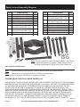
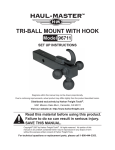
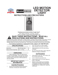
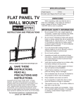
Specifications
14 PC. Gear Puller Set
Item 30305
Instructions & precautions
(Includes case, not shown)
Visit our website at:
http://www.harborfreight.com
Gear Pulling
Range
Pulls Gears 9/32 IN. to 3 IN.
Gear Puller
Arms
Spread to 5-3/4 IN.
Reach up to 4 IN.
Applications
Gear Pulling
Bearing Pulling & Separating
Timing Gear Pulling
Steering Wheel Pulling
Sprocket Pulling
Pulley Pulling
Sprocket and
Pulley Tapped
Hole Capacity
5/16 IN. - 18
3/8 IN. - 16
3/8 IN. 24
8 x 1.25 mm
Construction
Center Bolt is hardened Steel
Important Safety Information
Read this material before
using this product.
Failure to do so can result
in serious injury.
Save this manual.
Precautions
1. Assemble and use only according to
these instructions. Improper assembly
and usage can create hazards.
When unpacking, make sure that the
product is intact and undamaged.
If any parts are missing or broken,
please call 1‑800‑444‑3353
as soon as possible.
Copyright©
Tools®.
2011 by Harbor Freight
All rights reserved. No portion of this document
or any artwork contained herein may be
reproduced in any shape or form without the
express written consent of Harbor Freight
Tools. Diagrams within this document may
not be drawn proportionally. Due to continuing
improvements, actual product may differ slightly
from the product described herein. Tools required
for assembly and service may not be included.
For technical questions or replacement
parts, please call 1‑800‑444‑3353.
Manual Revised 11c
2. Wear ANSI-approved safety goggles
and heavy-duty work gloves
during assembly and usage.
3. Keep area clean and well lit.
4. Keep children and other
bystanders out of the area.
5. Do not use when tired or when under
the influence of drugs or medication.
6. Use as intended only.
7. Inspect before every use; do not
use if parts are loose or damaged.
8. Maintain product labels and
nameplates. These carry important
safety information. If unreadable
or missing, contact Harbor Freight
Tools for a replacement.
gear to be pulled, then tighten
the Nuts on both Pawls.
Operation Instructions
Read the entire Important
Safety Information
section at the beginning of
this document including
all text under subheadings
therein before set up or
use of this product.
Pulling Gears
Pawl (14a)
Washers (16)
Cone
Head for
Push Rod
(10)
Nut
(14b)
5. Screw the Push Rod (9) into the
shaft at the center of the gear
by turning the Head of the Push
Rod with a wrench (not included).
This will allow the gear to be
pulled clear of its position.
Separating Ball Bearings
Connecting Bolts
(7 & 8)
Bracket (6)
Bracket
(6)
Figure 1
1. Thread the Push Rod (9)
into the Bracket (6).
Washer
(16)
Flat Head
Insert (11)
Pawl
(15a)
Push Rod (9)
Nut
(15b) Washers (16)
Push
Rod
(9)
Separator
Bolt (4 & 5)
with Nut &
Washer
Bearing Separators (2 & 3)
2. Place a Washer (16), a Nut (14b or Figure 1
15b) and a Washer (16) onto the
1. Thread the Push Rod (9) into
Pawls (14a & 15a). Slide each Pawl
the Bracket (6), then slide
into a slot on the Bracket, as shown
the Flat Head Insert (11) into
above, so one Washer is below
the end of the Push Rod.
the Bracket and the Nut and other
2. Lay the Bearing Separators (2
Washer are above the Bracket.
& 3) so they face each other,
3. Slide the Cone Head Insert (10)
creating an open circle.
into the end of the Push Rod (9).
3. Remove the Nut and Washer
4. Slide the Pawls together until
from the Separator Bolts (4 &
they fit snuggly against the
5), then slide the Bolts through
REV 11c
Page 2
For technical questions, please call 1-800-444-3353.
SKU 30305
the Bearing Separator holes and
replace the Washers and Nuts.
Note: Do not tighten Bolts.
Maintenance
4. Slide a Washer (16) onto the two
Connecting Bolts (7 & 8) and then
slide them into the slots on the
Bracket, keeping the Washers
above the Bracket. Thread the
Bolt-ends into the holes on the
top of the Bearing Separators.
1. Before each use, inspect the
general condition of the tool. Check
for cracked or broken parts and
any other condition that may affect
its safe operation. If damaged,
have corrected before further use.
Note: A light coat of oil on the shaft
near the bearing gear and on the
Push Rod (9) is recommended
for difficult pulling jobs.
3. Coat all parts with a light oil to
prevent rust, then store them in
the case, in a clean, dry location.
2. Do not use damaged equipment.
5. Position the Bearing Separators
(2 & 3) around the base of the
Bearing to be separated.
6. Tighten each nut evenly.
7. Using an adjustable wrench (sold
separately), tighten the Push
Rod (9) against the center shaft
of the bearing to separate the
bearings from one another.
REV 11c
SKU 30305
For technical questions, please call 1-800-444-3353.
Page 3
Parts List and Assembly Diagram
Part
1
2
3
4
5
6
7
8
9
10
Description
Case (not shown)
Bearing Separator - 3/8" x 16T
Bearing Separator - 3/8" x 16T
Bolt for Separator - 1/2" x 12T
Bolt for Separator - 1/2" x 12T
Bracket
Connecting Bolt - 3/8" x 16T,
step down thread: M8 x 1.25
Connecting Bolt - 3/8" x 16T,
step down thread: M8 x 1.25
Push Rod
Cone Head for Push Rod
Qty
1
1
1
1
1
1
1
1
1
1
Part
11
12
13
14a
14b
15a
15b
16
17
7
Description
Flat Head for Push Rod
Connecting Bolt - 3/8" x 24T,
step down thread 5/16" x 18
Connecting Bolt - 3/8" x 24T,
step down thread 5/16" x 18
Pawl (3/8" x 16T)
Nut
Pawl (3/8" x 16T)
Nut
Flat Washer
Lube Oil Bottle (not shown)
8
12
2
15
13
4
Qty
1
1
1
1
1
1
1
4
1
5
6
14
3
9
10
16
Note: This kit includes two extra Connecting Bolts (12 & 13) for
use with other bearings or gears. These parts do not fit
the Bearing Separators (2 & 3) in this Gear Pulling Set.
11
Record Serial Number Here:
Note:
If product has no serial number, record month and year of purchase instead.
Note:
Some parts are listed and shown for illustration purposes only,
and are not available individually as replacement parts.
PLEASE READ THE FOLLOWING CAREFULLY
The manufacturer and/or distributor has provided the parts list and assembly
diagram in this document as a reference tool only. Neither the manufacturer
or distributor makes any representation or warranty of any kind to the
buyer that he or she is qualified to make any repairs to the product, or
that he or she is qualified to replace any parts of the product. In fact, the
manufacturer and/or distributor expressly states that all repairs and parts
replacements should be undertaken by certified and licensed technicians,
and not by the buyer. The buyer assumes all risk and liability arising out of
his or her repairs to the original product or replacement parts thereto,
or arising out of his or her installation of replacement parts thereto.
REV 11c
Page 4
For technical questions, please call 1-800-444-3353.
SKU 30305