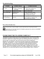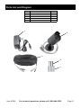
1
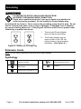
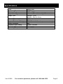
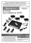
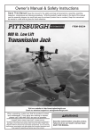
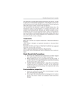
Owner’s Manual & Safety Instructions
Save This Manual Keep this manual for the safety warnings and precautions, assembly, operating,
inspection, maintenance and cleaning procedures. Write the product’s serial number in the back of the manual
near the assembly diagram (or month and year of purchase if product has no number).
Keep this manual and the receipt in a safe and dry place for future reference.
Weatherproof Color
Security Camera
with Night Vision
Visit our website at: http://www.harborfreight.com
Email our technical support at: [email protected]
ITEM 61208
When unpacking, make sure that the product is intact
and undamaged. If any parts are missing or broken,
please call 1-800-444-3353 as soon as possible.
Copyright© 2013 by Harbor Freight Tools®. All rights reserved.
No portion of this manual or any artwork contained herein may be reproduced in
any shape or form without the express written consent of Harbor Freight Tools.
Diagrams within this manual may not be drawn proportionally. Because of
continuing improvements, actual product may differ slightly from the product
described herein. Tools required for assembly and service may not be included.
Read this material before using this product.
Failure to do so can result in serious injury.
Save this manual.
WARNING SYMBOLS AND DEFINITIONS
This is the safety alert symbol. It is used to alert you to
potential personal injury hazards. Obey all safety messages
that follow this symbol to avoid possible injury or death.
Indicates a hazardous situation which, if not avoided,
will result in death or serious injury.
Indicates a hazardous situation which, if not avoided,
could result in death or serious injury.
Indicates a hazardous situation which, if not avoided,
could result in minor or moderate injury.
Addresses practices not related to personal injury.
Important Safety Information
Read all safety warnings and instructions.
Failure to follow the warnings and instructions may result in
electric shock, fire and/or serious injury.
Save all warnings and instructions for future reference.
Installation Precautions
1. Check local surveillance
laws before installation.
4. Wear ANSI-approved safety goggles
during installation.
2. Install only according to these
instructions. Improper installation
can create hazards.
5. Keep installation area clean and well lit.
6. Keep children and bystanders out
of the area during installation.
3. Do not overreach when installing
7. Do not install when tired or
this product. Keep proper footing
when under the influence of
and balance at all times. This enables
alcohol, drugs or medication.
better control in unexpected situations.
Page 2
For technical questions, please call 1-800-444-3353.
Item 61208
Use Precautions
1. This product is not a toy. Do not allow
children to play with or near this item.
2. Use as intended only.
3. Do not modify.
4. Maintain product labels and
nameplates. These carry
important safety information.
If unreadable or missing, contact
Harbor Freight Tools for a replacement.
Camera Safety Warnings
1. To prevent electric shock, do not
attempt to disassemble Camera. There
are no serviceable parts inside.
6. Handle Camera with care.
Camera could be damaged by
improper handling or storage.
2. Use supplied Power Adapter only.
7. WARNING: Handling the cord
on this product will expose you
to lead, a chemical known to
the State of California to cause
cancer, and birth defects or other
reproductive harm. Wash hands
after handling. (California Health &
Safety Code § 25249.5, et seq.)
3. The Power Adapter must match the
outlet. Never modify the plug in any
way. Unmodified plugs and matching
outlets will reduce risk of electric shock.
4. Do not expose the Power Adapter
to rain or wet conditions. Water
entering the Power Adapter will
increase the risk of electric shock.
5. Do not abuse the Power Adapter
cord. Never use the cord for
unplugging the plug from the
outlet. Keep cord away from
heat, oil, sharp edges or moving
parts. Damaged or entangled cords
increase the risk of electric shock.
8. The warnings, precautions, and
instructions discussed in this instruction
manual cannot cover all possible
conditions and situations that may
occur. It must be understood by the
operator that common sense and
caution are factors which cannot
be built into this product, but must
be supplied by the operator.
Service
Have your Camera Equipment serviced by a qualified repair
person using only identical replacement parts.
Save these instructions.
Item 61208
For technical questions, please call 1-800-444-3353.
Page 3
Grounding
To prevent electric shock and death from
incorrect grounding wire connection:
Check with a qualified electrician if you are in doubt as to whether the
outlet is properly grounded. Do not modify the Power Adapter plug
provided with the Camera. Never remove the grounding prong from the plug. Do not
use the Camera if the power cord or plug is damaged. If damaged, have it repaired
by a service facility before use. If the plug will not fit the outlet, have a proper outlet
installed by a qualified electrician.
1. The included Power Adapter
does not require grounding.
2. The Power Adapter may be
used in either of the 120 volt
outlets shown in the preceding
illustration. (See Figure A.)
Figure A: Outlets for 2-Prong Plug
Extension Cords
Note: Do not use an extension cord with the Power Adapter.
Symbology
Double Insulated
Canadian Standards
Association
V~
A
Volts Alternating Current
Amperes
Underwriters Laboratories, Inc.
Page 4
For technical questions, please call 1-800-444-3353.
Item 61208
Specifications
Lens
Horizontal Resolution
Effective Pixels
Night Vision Type
Image Type
Infrared Wavelength
Infrared Distance
Ingress Protection Rating
Video Connector
Camera Power Rating
Cable Length
Operating Temperature
Item 61208
Fixed 6 mm
400 TVL
648H x 488V
Infrared LEDs with Low Light Sensor
Daylight: Color
Infrared: Black & White
850nm
30 ft. (indoors)
IP65 - Protected from low pressure water jets
BNC
12VDC / 500 mA
60 ft.
14° - 122°F
For technical questions, please call 1-800-444-3353.
Page 5
Installation Instructions
Read the entire Important Safety Information section
at the beginning of this manual including all text under
subheadings therein before set up or use of this product.
To prevent serious injury from electric shock:
Unplug the Power Adapter from its electrical outlet and verify that installation
surface has no hidden utility lines before drilling or driving screws.
Components
Camera
Power Adapter
Hood
Power
(to Cable)
Lens
Video
(to Cable)
Power
(from Cable)
Cable - 60 ft.
Mounting
Hardware
Screws
Anchors
Video
(from Camera)
Power
(to Camera)
Video
(to DVR)
Power
(from Adapter)
Figure B
Page 6
For technical questions, please call 1-800-444-3353.
Item 61208
Before Mounting
1. Test Camera by connecting all cables
and making sure it functions properly.
2. Also test Camera in intended location
before mounting. When planning
mounting location and angle:
a.Take into consideration the length
of the Cable. Route the Cable so
as to avoid a tripping hazard.
b.Choose a location high enough so
that it is out of reach of children, but
still covers the desired viewing area.
3. Using the Base as a template,
mark locations of mounting
holes on mounting surface.
Note: Route Cable through slot on
Base to keep Base flush with mounting
surface while marking holes.
Cable
Slot
Mounting
Holes
c.Verify that installation surface
has no hidden utility lines before
drilling or driving screws.
d.To avoid mounting the Camera
upside down, make sure the
Hood is above the Lens.
e.Make sure no strong light will
shine directly into Camera Lens.
Base
Figure C
Mounting
Solid Surface
1. Using a drill bit slightly smaller
than the Screws, drill pilot holes
into the marked locations.
2. Position Camera so that mounting
holes align with pilot holes.
Note: Route Cable through slot on Base
to keep Base flush with mounting surface.
3. Drive Screws through mounting
holes in Base and into pilot holes
until the Camera is securely
attached to the mounting surface.
Hollow Surface
1. Using a drill bit slightly smaller
than the Anchors, drill holes
in the marked locations.
2. Tap Anchors into the holes until they are
almost flush with mounting surface.
4. Drive Screws through mounting
holes in Base and into anchor
holes until the Camera is securely
attached to the mounting surface.
3. Position Camera so that Mounting
Holes align with anchor holes.
Note: Route Cable through slot on Base
to keep Base flush with mounting surface.
Item 61208
For technical questions, please call 1-800-444-3353.
Page 7
Camera Adjustment
Adjustment
Wheel
1. Loosen Adjustment Wheel,
rotate Camera as needed, then
tighten Adjustment Wheel.
2. Loosen Adjustment Screw,
tilt Camera as needed, then
tighten Adjustment Screw.
Note: Only loosen Adjustment
Screw slightly, do not remove it.
Adjustment
Screw
Figure D
Cable Connections
CAUTION! Route the Cable so
as to avoid a tripping hazard.
4. Connect Power from Cable
to Power Adapter.
1. Connect Video from Camera to Cable.
5. Plug Power Adapter into a
120 volt electrical outlet.
2. Connect Power from Camera to Cable.
3. Connect Video from Cable to Video
Input Device (DVR, TV, Monitor, etc).
CAUTION! The Power Adapter MUST be
plugged in indoors in a clean, dry location.
Video Input Device
1
3
4
5
2
Figure E
Page 8
For technical questions, please call 1-800-444-3353.
Item 61208
Operating Instructions
Read the entire Important Safety Information section
at the beginning of this manual including all text under
subheadings therein before set up or use of this product.
1. Refer to the Video Input Device
manufacturer’s instructions for
operating the camera with the Device.
2. The Camera will operate continuously
while the Power Adapter is plugged in.
3. When not using the Camera, unplug the
Power Adapter from its electrical outlet.
Inspection, Maintenance, and Cleaning
Procedures not specifically explained in this manual must be performed only
by a qualified technician.
To prevent serious injury from Electric Shock:
Unplug the Power Adapter from its electrical outlet
before inspection, maintenance, or cleaning.
1. Periodically, inspect the general
condition of the Camera. Check for:
• loose hardware,
• damaged cord/electrical wiring,
• cracked or broken parts, and
• any other condition that may
affect its safe operation.
Item 61208
2. Periodically, wipe external
surfaces of Camera with clean cloth.
3. Maintain area surrounding
Camera, making sure obstacles
don’t interfere with visibility,
such as overgrown bushes.
For technical questions, please call 1-800-444-3353.
Page 9
Troubleshooting
Problem
Possible Causes
Probable Solutions
Camera does
not work.
1.No power at outlet.
2.Cables not properly
connected.
1.Check power at outlet.
2.Check that all cables are
securely connected.
Poor image quality.
Camera lens is dirty.
Clean Camera lens.
View undesirable.
Camera out of
adjustment.
Loosen Adjustment Screw,
tilt Camera as needed, then
tighten Adjustment Screw.
Image is upside
down/sideways.
Camera not mounted
correctly.
Loosen Adjustment Wheel,
rotate Camera as needed, then
tighten Adjustment Wheel.
Record Serial Number Here:
Note: If product has no serial number, record month and year of purchase instead.
Note: Some parts are listed and shown for illustration purposes only, and are not available
individually as replacement parts.
PLEASE READ THE FOLLOWING CAREFULLY
The manufacturer and/or distributor has provided the parts list and
assembly diagram in this manual as a reference tool only. Neither the
manufacturer or distributor makes any representation or warranty
of any kind to the buyer that he or she is qualified to make any
repairs to the product, or that he or she is qualified to replace any
parts of the product. In fact, the manufacturer and/or distributor
expressly states that all repairs and parts replacements should
be undertaken by certified and licensed technicians, and not by the
buyer. The buyer assumes all risk and liability arising out of his or
her repairs to the original product or replacement parts thereto, or
arising out of his or her installation of replacement parts thereto.
Page 10
For technical questions, please call 1-800-444-3353.
Item 61208
Parts List and Diagram
Part
1
2
3
4
5
Description
Power Adapter
Camera
Cable
Screw
Anchor
Qty.
1
1
1
3
3
1
2
3
4
5
Item 61208
For technical questions, please call 1-800-444-3353.
Page 11
Limited 90 Day Warranty
Harbor Freight Tools Co. makes every effort to assure that its products meet high
quality and durability standards, and warrants to the original purchaser that this product
is free from defects in materials and workmanship for the period of 90 days from the
date of purchase. This warranty does not apply to damage due directly or indirectly,
to misuse, abuse, negligence or accidents, repairs or alterations outside our facilities,
criminal activity, improper installation, normal wear and tear, or to lack of maintenance.
We shall in no event be liable for death, injuries to persons or property, or for incidental,
contingent, special or consequential damages arising from the use of our product.
Some states do not allow the exclusion or limitation of incidental or consequential
damages, so the above limitation of exclusion may not apply to you. This warranty
is expressly in lieu of all other warranties, express or implied,
including the warranties of merchantability and fitness.
To take advantage of this warranty, the product or part must be returned to us
with transportation charges prepaid. Proof of purchase date and an explanation
of the complaint must accompany the merchandise. If our inspection verifies
the defect, we will either repair or replace the product at our election or we may
elect to refund the purchase price if we cannot readily and quickly provide you
with a replacement. We will return repaired products at our expense, but if we
determine there is no defect, or that the defect resulted from causes not within the
scope of our warranty, then you must bear the cost of returning the product.
This warranty gives you specific legal rights and you may also
have other rights which vary from state to state.
3491 Mission Oaks Blvd. • PO Box 6009 • Camarillo, CA 93011 • (800) 444-3353