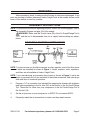
1
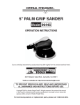
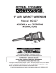
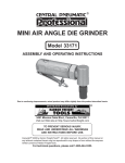
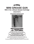
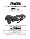
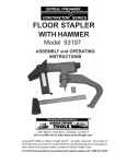
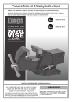
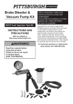
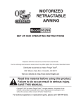
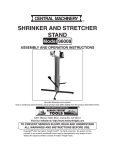
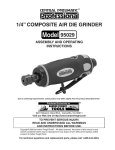
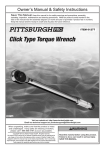
air punch/flange tool
Model 01110
Operation Instructions
Due to continuing improvements, actual product may differ slightly from the product described herein.
®
3491 Mission Oaks Blvd., Camarillo, CA 93011
Visit our website at: http://www.harborfreight.com
To prevent serious injury, read and understand
all warnings and instructions before use.
Copyright© 2007 by Harbor Freight Tools®. All rights reserved. No portion of this
manual or any artwork contained herein may be reproduced in any shape or form
without the express written consent of Harbor Freight Tools.
For technical questions or replacement parts, please call 1-800-444-3353.
REV 11h
Specifications
Maximum Sheet Metal Capacity
16 Gauge Mild Steel
Air Inlet
1/4” NPT Female
Air Consumption
4 CFM @ 90 PSI
Recommended Air Pressure
90 PSI
Throat Depth
5/8”
Crimp Width
7/8”
Punch Size
.19”
Hole Placement
.287 (Hole Center to Edge of Workplace)
Head Rotation
360°
Tool Length
9-3/4”
Weight
3 lb
Save This Manual
You will need this manual for the safety warnings and precautions, assembly, operating, inspection, maintenance and cleaning procedures, parts list and assembly diagram.
Keep your invoice with this manual. Write the invoice number on the inside of the front
cover. Write the product’s serial number in the back of the manual near the assembly
diagram, or write month and year of purchase if product has no serial number. Keep this
manual and invoice in a safe and dry place for future reference.
GENERAL SAFETY RULES
WARNING!
READ AND UNDERSTAND ALL INSTRUCTIONS
Failure to follow all instructions listed below may result in
serious injury.
SAVE THESE INSTRUCTIONS
Work Area
1.
Keep your work area clean and well lit. Cluttered benches and dark areas invite
accidents.
2.
Keep bystanders, children, and visitors away while operating. Distractions can
cause you to lose control. Provide barriers or shields as needed.
Personal Safety
1.
Stay alert. Watch what you are doing, and use common sense when operating. Do not use this Air Punch/Flange Tool while tired or under the influence
SKU 01110
For technical questions, please call 1-800-444-3353.
Page 2
of drugs, alcohol, or medication. A moment of inattention while operating may
result in serious personal injury.
2.
Dress properly. Do not wear loose clothing or jewelry. Contain long hair.
Keep your hair, clothing, and gloves away from moving parts. Loose clothes,
jewelry, or long hair can be caught in moving parts.
3.
Avoid accidental starting. Be sure the Throttle Lever (20) is NOT depressed
before attaching to air supply. Carrying the tool with your finger on the Throttle
Lever (20) invites accidents.
4.
Do not overreach. Keep proper footing and balance at all times. Proper footing
and balance enables better control in unexpected situations.
5.
Use safety equipment. Always wear eye protection. Nonskid safety shoes, hard
hat, or hearing protection must be used for appropriate conditions. Always wear
ANSI-approved safety goggles and heavy-duty work gloves when using or performing maintenance on this tool.
Tool Use And Care
1.
Use clamps (not included) or other practical ways to secure and support the
work piece to a stable platform. Holding the work by hand or against your body
is unstable and may lead to loss of control.
2.
Do not force the tool. Use the correct tool for your application. The correct
tool will do the job better and safer at the rate for which it is designed.
3.
Do not use the tool if the Throttle Lever (20) does not turn it on or off.
4.
Disconnect the air supply before making any adjustments, changing accessories, or storing the Air Punch/Flange Tool. Such preventive safety measures
reduce the risk of starting the tool accidentally.
5.
Store idle tools out of reach of children and other untrained persons. This
Air Punch/Flange Tool is dangerous in the hands of untrained users. Never allow
children to come in contact with this product.
6.
Maintain tools with care. Keep the Air Punch/Flange Tool clean. Properly maintained tools are less likely to bind and are easier to control. Do not use a damaged
tool. Tag damaged tools “Do not use” until repaired.
7.
Check for misalignment or binding of moving parts, breakage of parts, and
any other condition that may affect the tool’s operation. If damaged, have
the tool serviced by a qualified technician before using. Many accidents are
caused by poorly maintained tools.
SKU 01110
For technical questions, please call 1-800-444-3353.
Page 3
Service
1.
Tool service must be performed only by qualified repair personnel. Service or
maintenance performed by unqualified personnel could result in a risk of injury.
2.
When servicing a tool, use only identical replacement parts. Follow instructions in the “Inspection, Maintenance, And Cleaning” section of this manual.
Use of unauthorized parts or failure to follow maintenance instructions may create
a risk damage to your project and/or personal injury.
SPECIFIC SAFETY RULES
1.
Do not remove the Plate Guard (8).
2.
Wear heavy-duty gloves and keep hands away from moving parts.
3.
Use compressed air only. Clean, dry, regulated compressed air at no more than
90 PSI. Never use oxygen, carbon dioxide, combustible gasses, or any other bottled
gas as a power source for this tool. Do not exceed 90 PSI.
4.
Maintain labels and nameplates on the tool. These carry important information.
If unreadable or missing, contact Harbor Freight Tools for a replacement.
5.
Maintain a safe working environment. Make sure there is adequate surrounding
workspace.
6.
Avoid unintentional starting. Make sure you are prepared to begin work before
attaching the air supply and pressing the Throttle Lever.
7.
Never leave the tool unattended when it is plugged into an air supply. Unplug
it from its air supply before leaving.
8.
WARNING: The brass components of this product contain lead, a chemical
known to the State of California to cause birth defects (or other reproductive
harm). (California Health & Safety code § 25249.5, et seq.)
9.
Be sure to read and follow all safety warnings and instructions in the manual
provided by the manufacturer of the air compressor you are using with this
Air Punch/Flange Tool.
10.
Be aware of material thickness. Never try to punch or flange material thicker than
16 gauge. Doing so may damage the tool and/or cause personal injury.
11.
Material guide and support may be needed. When working with large materials,
you may need the help of an assistant, or support stands (not included) in order to
maintain a straight flange or punch consistent holes.
SKU 01110
For technical questions, please call 1-800-444-3353.
Page 4
Unpacking
When unpacking, check to make sure that the item is intact and undamaged. If any
parts are missing or broken, please call Harbor Freight Tools at the number shown on the
cover of this manual as soon as possible.
Assembly Instructions
NOTE: For additional information regarding the parts listed in the following pages, refer to
the Assembly Diagram on page 10 of this manual.
WARNING! Make sure the Throttle Lever (20) of the Air Punch/Flange Tool is
“OFF” and the tool is disconnected from its air supply before making any adjustments.
AIR SUPPLY ASSEMBLY INSTRUCTIONS
Figure 1
NOTE: For best service you should incorporate an oiler, regulator, and in-line filter (none
of which are included) as shown in Figure 1. Hoses, couplers, oilers, regulators,
and filters are all available at Harbor Freight Tools.
NOTE: If you are not using an automatic oiler system as shown in Figure 1, add a few
drops of pneumatic tool oil (not included) to the airline connection. Add a few drops
after each hour of continual operation.
2.
Prepare a 1/4” air connector (not included) by wrapping the threads with plumbers
tape before connecting to the Air Inlet (19) on the bottom of the Air Punch/Flange
Tool. Thread the Air Hose from your compressor to the Air Punch/Flange Tool at
the Air Inlet (19).
3.
Set the air pressure on your compressor to 90 PSI. Do not exceed 90 PSI.
4.
Frequently check the air connections to make sure they remain secure.
SKU 01110
For technical questions, please call 1-800-444-3353.
Page 5
Operation Instructions
PUNCHING
1.
WARNING: Always wear heavy-duty leather gloves when handling sheet
metal. Sharp edges can cause severe injury. Always wear ANSI-approved safety
goggles.
2.
Pre-mark the desired location of each hole you wish to punch on the workpiece.
NOTE: If the workpiece is to be both punched and flanged, flange it first, then measure for
the hole placement. Flanging will change the dimensions of the workpiece.
3.
Connect the Air Punch/Flange Tool to your air supply. Do not exceed 90 PSI.
4.
Insert the edge of the workpiece between the Punch Die (3) and the Punch (6).
Make sure your marks are aligned with the Punch Die (3).
5.
Squeeze the Throttle Lever (20) and the Punch (6) will pierce the workpiece.
6.
Align the tool with the next mark on the workpiece and repeat step 5 until the job
is finished.
7.
Disconnect the air supply.
8.
WARNING: After disconnecting the Air Punch/Flange Tool from the air supply
there could still be enough air pressure to fire the Punch/Flange. After making
sure the air supply is disconnected, ALWAYS fire the Punch/Flange repeatedly to
make sure all air is bled from the tool.
FLANGING
1.
WARNING: Always wear heavy-duty leather gloves when handling sheet
metal. Sharp edges can cause severe injury. Always wear ANSI-approved safety
goggles.
2.
Measure and cut the workpiece to the correct dimensions.
3.
Connect the Air Punch/Flange Tool to your air supply. Do not exceed 90 PSI.
4.
Secure the workpiece in a vise or use another appropriate clamping method.
5.
Insert the workpiece into the flanging jaw between the Anvil (9) and the Clamp (1).
Make sure the workpiece is all the way flush against the back of both the Anvil (9)
and the Clamp (1). Squeeze the Throttle Lever (20) and the Anvil (9) will be driven
against the Clamp (1) forming a flange.
6.
Release the Throttle Lever (20). Slide the tool along the edge of the workpiece to
where the Anvil (9) and the Clamp (1) overlap part of the workpiece you just flanged.
Repeat step 5.
SKU 01110
For technical questions, please call 1-800-444-3353.
Page 6
7.
Repeat steps 5 and 6 until until the entire length you wanted to flange is finished.
8.
Disconnect the air supply.
9.
WARNING: After disconnecting the Air Punch/Flange Tool from the air supply
there could still be enough air pressure to fire the Punch/Flange. After making
sure the air supply is disconnected, ALWAYS fire the Punch/Flange repeatedly to
make sure all air is bled from the tool.
PLEASE READ THE FOLLOWING CAREFULLY
The manufacturer and/or distributor has provided the parts
list and assembly diagram in this manual as a reference tool only.
Neither the manufacturer or distributor makes any representation
or warranty of any kind to the buyer that he or she is qualified
to make any repairs to the product, or that he or she is qualified
to replace any parts of the product. In fact, the manufacturer
and/or distributor expressly states that all repairs and parts
replacements should be undertaken by certified and licensed
technicians, and not by the buyer. The buyer assumes all risk and
liability arising out of his or her repairs to the original product
or replacement parts thereto, or arising out of his or her installation of replacement parts thereto.
Record Product’s Serial Number Here:
Note: If product has no serial number, record month and year of purchase instead.
Note: Some parts are listed and shown for illustration purposes only, and are not available
individually as replacement parts.
SKU 01110
For technical questions, please call 1-800-444-3353.
Page 7
INSPECTION, MAINTENANCE, AND CLEANING
WARNING! Make sure the Throttle Lever (20) is in its “OFF” position and that
the Air Punch/Flange Tool is disconnected from its air supply before performing any
inspection, maintenance, or cleaning procedures.
1.
BEFORE EACH USE, inspect the general condition of the tool. Check for loose
screws, misalignment or binding of moving parts, cracked or broken parts, and
any other condition that may affect its safe operation. If abnormal noise or vibration occurs, have the problem corrected before further use. Do not use damaged
equipment.
2.
WHEN NECESSARY, fill the hydraulic system with a high quality hydraulic oil. Remove the Oil Plug (13), refill and then replace the Oil Plug (13). See Figure 2
3.
To adjust the Punch, loosen the Set Screw (2) and rotate the tool head. After making needed adjustment, tighten the Set Screw (2). See Figure 2
Maintenance Chart
Before
Maintenance Type
Use
Inspect tool for damage
(see #1 above)
X
Check hydraulic oil
(see #2 above)
X
Wipe off with clean, moist
cloth
SKU 01110
After
Use
X
For technical questions, please call 1-800-444-3353.
Page 8
Troubleshooting
Problem
Possible Causes
Punch/Flange will not
start
Probable Solutions
1. Air supply not connected.
2. Air hose/hoses not securely
connected, or damaged and
leaking air.
1. Check, make sure air supply is
properly connected to the tool.
2. Check all air hose and connections.
if any air hose damage is found,
replace the damaged hose/hoses.
Do not apply duct tape or wraps of
any kind to the damaged area.
Punch/Flange will
1. Possible dirt or debris gathered in
not operate smoothly
moving parts.
when punching and/or
flanging.
1. Make sure Anvil (9) and Clamp (1)
as well as the Punch Die (3) and
Punch (6) are wiped clean of any
dirt or debris.
PARTS LIST
Part
Description
Q’ty
Part
Description
Q’ty
1
Clamp
1
20
Throttle Lever
1
2
Set Screw
1
21
Spring Pin
1
3
Punch Die
1
22
O-ring
1
4
Guide Bushing
1
23
Push Rod
1
5
Cup Spring
13
24
Spring
1
6
Punch
1
25
Valve
1
7
Screw
2
26
Spring
1
8
Plate Guard
1
27
O-ring
1
9
Anvil
1
28
Screw
1
10
Oil Seal
1
29
O-ring
1
11
Support Ring
1
30
Support Ring
1
12
O-ring
1
31
Hydraulic Piston
1
13
Oil Plug
1
32
O-ring
1
14
O-ring
1
33
Support Ring
2
15
Hydraulic Cylinder
1
34
Spring
1
16
Air Cylinder
1
35
Piston
1
17
Plastic Wrap
1
36
O-ring
1
18
Valve Body
1
37
Spring Washer
1
19
Air Inlet
1
SKU 01110
For technical questions, please call 1-800-444-3353.
Page 9
ASSEMBLY DIAGRAM
REV 07e
SKU 01110
For technical questions, please call 1-800-444-3353.
Page 10
90 DAY WARRANTY
Harbor Freight Tools Co. makes every effort to assure that its products meet high quality
and durability standards, and warrants to the original purchaser that this product is free
from defects in materials and workmanship for the period of 90 days from the date of
purchase. This warranty does not apply to damage due directly or indirectly, to misuse,
abuse, negligence or accidents, repairs or alterations outside our facilities, criminal activity,
improper installation, normal wear and tear, or to lack of maintenance. We shall in no event
be liable for death, injuries to persons or property, or for incidental, contingent, special or
consequential damages arising from the use of our product. Some states do not allow the
exclusion or limitation of incidental or consequential damages, so the above limitation of
exclusion may not apply to you. This warranty is expressly in lieu of all other warranties,
express or implied, including the warranties of merchantability and fitness.
To take advantage of this warranty, the product or part must be returned to us with
transportation charges prepaid. Proof of purchase date and an explanation of the complaint
must accompany the merchandise. If our inspection verifies the defect, we will either
repair or replace the product at our election or we may elect to refund the purchase price
if we cannot readily and quickly provide you with a replacement. We will return repaired
products at our expense, but if we determine there is no defect, or that the defect resulted
from causes not within the scope of our warranty, then you must bear the cost of returning
the product.
This warranty gives you specific legal rights and you may also have other rights which
vary from state to state.
3491 Mission Oaks Blvd. • PO Box 6009 • Camarillo, CA 93011 • (800) 444-3353
REV 11h
SKU 01110
For technical questions, please call 1-800-444-3353.
Page 11