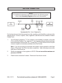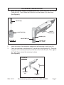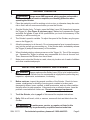
1
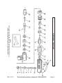
MINI AIR ANGLE DIE GRINDER
Model 33171
ASSEMBLY AND OPERATING INSTRUCTIONS
Due to continuing improvements, actual product may differ slightly from the product described herein.
®
3491 Mission Oaks Blvd., Camarillo, CA 93011
Visit our Web site at: http://www.harborfreight.com
TO PREVENT SERIOUS INJURY,
READ AND UNDERSTAND ALL WARNINGS
AND INSTRUCTIONS BEFORE USE.
Copyright© 2005 by Harbor Freight Tools®. All rights reserved. No portion of this manual or
any artwork contained herein may be reproduced in any shape or form without the express
written consent of Harbor Freight Tools.
For technical questions, please call 1-800-444-3353.
PRODUCT SPECIFICATIONS
Item
Description
Collet Size
1/4"
Air Inlet
1/4" NPT
Maximum Air Pressure
90 PSI
Air Consumption
4 CFM @ 90 PSI
Maximum RPM
21,000
Length
about 5"
Accessories
Collet Wrench (Qty. 2)
UNPACKING
When unpacking, check to make sure all the parts shown on the Parts List on page 9 are
included. If any parts are missing or broken, please call Harbor Freight Tools at the number
shown on the cover of this manual as soon as possible.
SAVE THIS MANUAL
You will need this manual for the safety warnings and precautions, assembly, operating,
inspection, maintenance and cleaning procedures, parts list and assembly diagram. Keep
your invoice with this manual. Write the invoice number on the inside of the front cover.
Keep this manual and invoice in a safe and dry place for future reference.
GENERAL SAFETY RULES
WARNING!
READ AND UNDERSTAND ALL INSTRUCTIONS
Failure to follow all instructions listed in the following
pages may result in fire, and/or serious injury.
SAVE THESE INSTRUCTIONS
SKU 33171
For technical questions, please call 1-800-444-3353.
Page 2
WORK AREA
1.
Keep your work area clean and well lit. Cluttered benches and dark areas invite
accidents.
2.
Do not operate pneumatic tools in explosive atmospheres, such as in the
presence of flammable liquids, gases, or dust. Pneumatic tools create sparks
which may ignite flammables.
3.
Keep bystanders, children, and visitors away while operating a pneumatic
tool. Distractions can cause you to lose control. Protect others in the work area
from debris such as chips and sparks. Provide barriers or shields as needed.
PERSONAL SAFETY
1.
Stay alert. Watch what you are doing, and use common sense when operating
a pneumatic tool. Do not use a pneumatic tool while tired or under the influence of drugs, alcohol, or medication. A moment of inattention while operating
pneumatic tools may result in serious personal injury.
2.
Dress properly. Do not wear loose clothing or jewelry. Contain long hair. Keep
your hair, clothing, and gloves away from moving parts. Loose clothes, jewelry,
or long hair can be caught in moving parts.
3.
Avoid accidental starting. Be sure the Trigger (4) is off before connecting to
the air supply. Carrying pneumatic tools with your finger on the Trigger, or connecting pneumatic tools to the air supply with the Trigger on, invites accidents.
4.
Remove both Spanners before turning on the tool. A Spanner (27) that is left
attached to a rotating part of the tool may result in personal injury.
5.
Do not overreach. Keep proper footing and balance at all times. Proper footing
and balance enables better control of the tool in unexpected situations.
6.
Use safety equipment. Always wear ANSI approved safety goggles underneath a full face shield, a dust mask or respirator, and hearing protection.
TOOL USE AND CARE
1.
Use clamps or other practical ways to secure and support the workpiece to a
stable platform. Holding the work by hand is unstable and may lead to loss of
control. Only work on a workpiece that is properly secured.
2.
Do not force the tool. Use the correct tool for your application. The correct tool
will do the job better and safer at the rate for which it is designed.
3.
Do not use the power tool if the Trigger (4) does not turn it on or off. Any tool
that cannot be controlled with its Trigger is dangerous and must be replaced.
SKU 33171
For technical questions, please call 1-800-444-3353.
Page 3
4.
Disconnect the air hose from the tool before making any adjustments, changing accessories, or storing the tool. Such preventive safety measures reduce the
risk of starting the tool accidentally.
5.
Store idle tools out of reach of children and other untrained persons. Tools are
dangerous in the hands of untrained users.
6.
Maintain tools with care. Do not use a damaged tool. Tag damaged tools “Do not
use” until repaired.
7.
Check for misalignment or binding of moving parts, breakage of parts, loose
parts, and any other condition that may affect the tool’s operation. If damaged, have the tool serviced before using. Many accidents are caused by poorly
maintained tools.
8.
Use only accessories that are recommended by the manufacturer for your
model. Accessories that may be suitable for one tool may become hazardous when
used on another tool.
SERVICE
1.
Tool service must be performed only by qualified repair personnel. Service
or maintenance performed by unqualified personnel could result in a risk of injury.
2.
When servicing a tool, use only identical replacement parts. Follow instructions in the “Inspection, Maintenance, And Cleaning” section of this manual.
Use of unauthorized parts or failure to follow maintenance instructions may create a
risk of injury.
SKU 33171
For technical questions, please call 1-800-444-3353.
Page 4
SPECIFIC SAFETY RULES
1.
Maintain labels and nameplates on the Grinder. These carry important information.
If unreadable or missing, contact Harbor Freight Tools for a replacement.
2.
Always grip the Grinder firmly when operating the tool.
3.
Always use accessories that have an RPM rating of at least 21,000 and a 1/4”
diameter shank. Using accessories not rated to meet the RPM capacity of this tool
or with an improperly sized shank can result in damaged accessories, personal
injury, and/or property damage.
4.
Use clean, dry, regulated, compressed air at 90 PSI. Do not exceed the
recommended 90 PSI. Never use oxygen, carbon dioxide, combustible gases, or
any other bottled gas as a power source for this tool.
5.
Always disconnect the Grinder from its compressed air supply source, and
squeeze the Trigger (4) to verify that the tool cannot operate before performing
any maintenance or services.
6.
Before using the Grinder, make sure that any accessories are properly attached
to the tool. Make sure to wrench tighten the collet before use.
7.
Check accessories for any signs of excessive wear or damage before use.
DO NOT USE DAMAGED ACCESSORIES.
8.
Accessories may become hot while grinding. Allow accessories to completely
stop and cool before touching.
9.
Allow the accessory to move at full speed before feeding them into the workpiece. Do not force the accessory into the workpiece when grinding. Apply moderate pressure, allowing it to grind without being forced. When turning off the Grinder,
allow the accessory to stop on its own; do not press against it to stop it.
10.
Industrial applications must follow OSHA requirements.
11.
WARNING! The brass components of this product contain lead, a chemical known
to the State of California to cause birth defects (or other reproductive harm).
(California Health & Safety code § 25249.5, et seq.)
12.
WARNING! The warnings, precautions, and instructions discussed in this manual
cannot cover all possible conditions and situations that may occur. The operator
must understand that common sense and caution are factors which cannot be built
into this product, but must be supplied by the operator.
SKU 33171
For technical questions, please call 1-800-444-3353.
Page 5
AIR LINE CONNECTION
NOTE:
For additional references to the parts listed in the following pages,
refer to the Assembly Diagram at the end of this manual.
Die
Grinder
For best service you should incorporate an oiler, regulator, and inline filter, as shown in the
diagram above. Hoses, couplers, oilers, regulators, and filters are all available at Harbor
Freight Tools.
1.
You will need to prepare a 1/4” air connector (not included) to connect to the Inlet
(10) on the Die Grinder. First, wrap the 1/4” air connector with pipe thread seal tape
before threading it into the Inlet (10). Connect the 3/8” ID Air Source Hose to a quick
connect coupler (not included), and then to the Die Grinder.
Note: If you are not using an automatic oiler system, before operation, add a few
drops of Pneumatic Tool Oil to the airline connection. Add a few drops more after
each hour of continual use.
2.
Set the air pressure on the regulator to 90 PSI. Do not exceed the maximum air
pressure of 90 PSI.
3.
Check the air connection for leaks. Disconnect from the air source.
SKU 33171
For technical questions, please call 1-800-444-3353.
Page 6
ACCESSORY INSTALLATION
1.
Make sure the air supply is disconnected first. Insert the Collet (24) into the
Collet Nut (25). Then, thread the Collet Nut onto the Spindle (33) a few turns.
(See Figure A.)
COLLET (24)
SAFETY
LEVER (39)
COLLET NUT (25)
SPINDLE (33)
COLLET NUT (25)
FIGURE A
COLLET (24)
(NOT SHOWN)
2.
Insert the shank of the accessory upward into the flared end of the Collet (24).
3.
Place the small end of the Spanner (27) on the flats of the Spindle (33). Place the
large end of the other Spanner (27) on the flats of the Collet Nut (25). Then, tighten
the Collet Nut to secure the accessory in place.
(See Figure B.)
FIGURE B
TIGHTEN
SPANNER
(27)
SKU 33171
SPANNER
(27)
For technical questions, please call 1-800-444-3353.
Page 7
GRINDER OPERATION
1.
WARNING! Always wear ANSI approved safety goggles underneath a
full face shield, a dust mask or respirator, and hearing protection when
operating the Grinder.
2.
Place the material you will be working on into a vise, or otherwise clamp the material so that it will not move around when you use the Grinder.
3.
Grip the Grinder firmly. To begin, press the Safety Lever (39) forward and squeeze
the Trigger (4). (See Figure A, previous page.) Make sure to squeeze the Trigger
and allow the grinder to spin at full speed before you touch the accessory to the
material you will be working on.
4.
The Grinder’s speed is variable. To adjust the speed of the Grinder, vary the pressure on the Trigger (4).
5.
Allow the accessory to do the work. Do not use excessive force to press the accessory into the surface you are working on. If the Grinder stalls, immediately release
the Trigger (4) and pull the accessory off the surface.
6.
When finished grinding, release pressure on the Trigger (4). Turn off the compressor. Squeeze the Trigger to release any compressed air in the air line and tool.
Then, disconnect the Grinder from the air hose.
7.
Make sure to store the Grinder in a safe, clean, dry location out of reach of children
and other unauthorized people.
INSPECTION, MAINTENANCE, AND CLEANING
1.
WARNING! Always make sure the Safety Lever (39) is in its locked position,
and disconnect the Grinder from its compressed air supply before performing any
inspection, adjustments, maintenance, or cleaning.
2.
Before each use, inspect the general condition of the Grinder. Check for loose
screws, misalignment or binding of moving parts, cracked or broken parts,
damaged air hoses, loose, cracked, or bent accessories, and any other condition
that may affect its safe operation. If abnormal noise or vibration occurs, have the
problem corrected before further use. Do not use damaged equipment.
3.
To oil the Grinder, refer to page 6 of this manual for complete instructions.
4.
Daily: With a soft brush, cloth, or vacuum, remove all dust and debris from the
Grinder.
5.
WARNING! All maintenance, service, or repairs not listed in this
manual should only be performed by a qualified service technician.
SKU 33171
For technical questions, please call 1-800-444-3353.
Page 8
PLEASE READ THE FOLLOWING CAREFULLY
THE MANUFACTURER AND/OR DISTRIBUTOR HAS PROVIDED THE PARTS LIST AND ASSEMBLY
DIAGRAM IN THIS MANUAL AS A REFERENCE TOOL ONLY. NEITHER THE MANUFACTURER OR
DISTRIBUTOR MAKES ANY REPRESENTATION OR WARRANTY OF ANY KIND TO THE BUYER THAT
HE OR SHE IS QUALIFIED TO MAKE ANY REPAIRS TO THE PRODUCT, OR THAT HE OR SHE IS
QUALIFIED TO REPLACE ANY PARTS OF THE PRODUCT. IN FACT, THE MANUFACTURER AND/OR
DISTRIBUTOR EXPRESSLY STATES THAT ALL REPAIRS AND PARTS REPLACEMENTS SHOULD BE
UNDERTAKEN BY CERTIFIED AND LICENSED TECHNICIANS, AND NOT BY THE BUYER. THE BUYER
ASSUMES ALL RISK AND LIABILITY ARISING OUT OF HIS OR HER REPAIRS TO THE ORIGINAL
PRODUCT OR REPLACEMENT PARTS THERETO, OR ARISING OUT OF HIS OR HER INSTALLATION
OF REPLACEMENT PARTS THERETO.
PARTS LIST
Part
Description
Q'ty
Part
Description
Q'ty
1
Housing
1
21
Air Regulator
1
2
Pin
1
22
Pinion Gear
1
4
Trigger
1
23
Retainer
1
5
Throttle Valve
1
24
Collet (1/4")
1
7
O-ring
1
25
Collet Nut
1
8
Valve Spring
1
26
Housing Lock Ring
1
9
O-ring
1
27
Spanner
2
10
Inlet
1
28
Angle Head Housing
1
11
O-ring
1
30
Spindle Gear
1
12
Rotor Brush
1
31
Clamp Nut
1
13
Ball Bearing
2
32
Key
1
14
Rear End Plate
1
33
Spindle
1
15
Rotor
1
34
Bushing
1
16
Rotor Blade
4
37
Oil Cap
1
17
Pin
2
38
Spring
1
18
Cylinder
1
39
Safety Lever
1
19
Front End Plate
1
40
Roll Pin
1
20
Ball Bearing
2
NOTE:
Some parts are listed and shown for illustration purposes only,
and are not available individually as replacement parts.
SKU 33171
For technical questions, please call 1-800-444-3353.
Page 9
ASSEMBLY DIAGRAM
NOTE:
Some parts are listed and shown for illustration purposes only,
and are not available individually as replacement parts.
Page 10
For technical questions, please call 1-800-444-3353.
SKU 33171