1
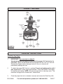
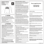
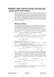
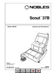
1” GAS IMPACT WRENCH
Model 95666
ASSEMBLY AND OPERATING INSTRUCTIONS
Due to continuing improvements, actual product may differ slightly from the product described herein.
CAUTION!
Your Warranty Is Voided If:
You do not operate the Gas Impacrt Wrench with the proper 25:1 fuel mix in its fuel tank.
Never run the Engine with an improper fuel mix, low or no fuel mix.
Running the Engine with an improper fuel mix, low or no fuel mix, will permanently damage the unit.
®
3491 Mission Oaks Blvd., Camarillo, CA 93011
Visit our Web site at: http://www.harborfreight.com
TO PREVENT SERIOUS INJURY,
READ AND UNDERSTAND ALL WARNINGS
AND INSTRUCTIONS BEFORE USE.
©
Copyright 2007 by Harbor Freight Tools®. All rights reserved. No portion of this
manual or any artwork contained herein may be reproduced in any shape or form
without the express written consent of Harbor Freight Tools.
For technical questions, please call 1-800-444-3353.
PRODUCT SPECIFICATIONS
Item
Drive Size
Maximum Bolt Capacity
Output Torque Range
Gear Box Settings
Engine Specifications
Accessories
Net Weight
Description
1”
1-5/8”
406 < - > 1250 Ft./Lb.
Reverse/Neutral/Forward
Engine Type: Two-Stroke / Forced Air Cooling / Single Cylinder / Recoil Start
Engine Displacement: 51.7 cc
Engine Idling RPM: 2700
Engine No Load RPM: 9880
Engine Torque RPM: 7120
Fuel Tank Capacity: 34 Ounces (0.26 Gal.)
Fuel Mixture Required: 25:1 (25 Parts Unleaded Gasoline/1 Part 2-Cycle Oil)
Spark Plug Type: Torch ® L7T
EPA Approved
Side D-Handle (Qty. 1) / Top D-Handle (Qty. 1) / Spark Plug Wrench (Qty. 1)
4mm Hex Wrench (Qty. 1) / 5mm Hex Wrench (Qty. 1) / 6mm Hex Wrench (Qty. 1)
10 < - > 13mm Spanner (Qty. 1)
39.6 Pounds
This product requires a 25:1 ratio of fuel and 2-cycle oil to be added to its fuel tank before starting.
Attempting to start the Engine with an improper fuel mix, low or no fuel mix WILL ruin the Engine
and void the warranty.
The Engine’s Carburetor may need to be adjusted by a qualified mechanic for efficient highaltitude use.
The Emission Control System for this product’s engine is warranted for standards set by the U.S.
Environmental Protection Agency. For warranty information, refer to the last pages of this manual.
SAVE THIS MANUAL
You will need this manual for the safety warnings and precautions, assembly, operating,
inspection, maintenance and cleaning procedures, parts list and assembly diagram.
Keep your invoice with this manual. Write the invoice number on the inside of the front
cover. Keep this manual and invoice in a safe and dry place for future reference.
GENERAL SAFETY RULES AND PRECAUTIONS
WARNING!
READ AND UNDERSTAND ALL INSTRUCTIONS
Failure to follow all instructions listed below may result in
electric shock, fire, and/or serious injury.
SAVE THESE INSTRUCTIONS
WORK AREA
1.
Keep your work area clean and well lit. Cluttered benches and dark areas
invite accidents.
2.
SKU 95666
Do not operate power tools in explosive atmospheres, such as in the
presence of flammable liquids, gases, or dust. Power tools create
For technical questions, please call 1-800-444-3353
PAGE 2
sparks which may ignite the dust or fumes.
3.
Keep bystanders, children, and visitors away while operating a power tool.
Distractions can cause you to lose control. Provide barriers or shields as
needed. Children should never be in the work area.
PERSONAL SAFETY
1.
Stay alert. Watch what you are doing, and use common sense when operating a power tool. Do not use a power tool while tired or under the influence of drugs, alcohol, or medication. A moment of inattention while operating power tools may result in serious personal injury.
2.
Dress properly. Do not wear loose clothing or jewelry. Contain long hair.
Keep your hair, clothing, and gloves away from moving parts. Loose
clothes, jewelry, or long hair can be caught in moving parts.
3.
Avoid accidental starting. Be sure the Stop Button (103) is in its “STOP”
position before moving the Impact Wrench and before performing any
service, maintenance, or cleaning procedures on the unit.
4.
Remove adjusting keys or wrenches before turning the Impact Wrench on.
A wrench or a key that is left attached to a rotating part of the machine may
result in personal injury.
5.
Do not overreach. Keep proper footing and balance at all times. Proper
footing and balance enables better control of the power tool in unexpected
situations.
TOOL USE AND CARE
1.
Do not force the tool. Use the correct tool for your application. The correct
tool will do the job better and safer at the rate for which it is designed.
2.
Do not use the Impact Wrench if the Stop Button (103) does not turn it on
or off. Any tool that cannot be controlled with its Stop Button is dangerous and
must be replaced.
3.
Store idle tools out of reach of children and other untrained persons. Tools
are dangerous in the hands of untrained users.
4.
Maintain tools with care. Properly maintained tools are less likely to malfunction and are easier to control. Do not use a damaged tool. Tag damaged tools
“Do not use” until repaired.
SKU 95666
For technical questions, please call 1-800-444-3353
PAGE 3
5.
Check for misalignment or binding of moving parts, breakage of parts, and
any other condition that may affect the tool’s operation. If damaged, have
the tool serviced before using. Many accidents are caused by poorly maintained tools.
6.
Use only accessories that are recommended by the manufacturer for your
model. Accessories that may be suitable for one tool may become hazardous
when used on another tool.
SERVICE
1.
Tool service must be performed only by qualified repair personnel. Service
or maintenance performed by unqualified personnel could result in a risk of injury.
2.
When servicing a tool, use only identical replacement parts. Follow
instructions in the “Inspection, Maintenance, And Cleaning” section of this
manual. Use of unauthorized parts or failure to follow maintenance instructions
may create a risk of electric shock or injury.
SPECIFIC SAFETY RULES AND PRECAUTIONS
1.
IMPORTANT! Your Warranty is voided if:
You do not operate the Impact Wrench with the proper 25:1 fuel mix in its
fuel tank. Never run the Engine with an improper fuel mix, low or no fuel mix.
Running the Engine with an improper fuel mix, low or no fuel mix, will permanently damage the unit.
2.
Maintain labels and nameplates on the Impact Wrench. These carry important information. If unreadable or missing, contact Harbor Freight Tools for a
replacement.
WARNING! Always wear safety equipment. When operating
the Impact Wrench, always wear ANSI approved safety impact eye
goggles, hearing protection, heavy duty work gloves, sturdy work
boots, and head protection.
3.
4.
Never leave the Impact Wrench unattended when it is running. Turn off the
Engine before leaving.
5.
Do not allow children and other unauthorized people to handle or play with
the Impact Wrench. Children should be kept out of the work area. Also, store
the Impact Wrench in a location out of reach of children.
SKU 95666
For technical questions, please call 1-800-444-3353
PAGE 4
6.
Make sure the Impact Wrench is completely stopped before changing the
rotational direction of the tool.
7.
Always maintain a firm grip on the Impact Wrench with both hands. Beware
of start up torque.
8.
WARNING! This Impact Wrench is designed for outdoor use only. Do
not operate the Impact Wrench in a closed area or in a poorly ventilated area.
When running, the Engine of this product produces carbon monoxide, a
colorless, odorless, toxic gas that, when inhaled, can cause serious personal injury or death.
FIRE AND EXPLOSION PRECAUTIONS
1.
Gasoline fuel and fumes are flammable, and potentially explosive.
Use proper fuel storage and handling procedures. Always have multiple
ABC class fire extinguishers nearby.
2.
Keep the Impact Wrench and surrounding areas clean at all times.
3.
When spills of fuel or oil occur, they must be cleaned up immediately. Dispose of fluids and cleaning materials as per any local, state, or federal codes and
regulations. Store oil rags in a covered metal container.
4.
Never store fuel or other flammable materials near the Impact Wrench.
5.
Do not smoke, or allow sparks, flames, or other sources of ignition around
the Impact Wrench.
6.
Keep grounded conductive objects, such as tools, away from exposed, live
electrical parts and connections to avoid sparking or arcing. These events
could ignite fumes or vapors.
7.
Do not refill the Fuel Tank while the Engine is running or while the Engine is
still hot. Do not operate the Impact Wrench with known leaks in the fuel system.
8.
Use only Engine manufacturer recommended fuel and oil.
MECHANICAL PRECAUTIONS
1.
Prior to performing service, maintenance, or cleaning procedures, always
make sure the Stop Button (103) is in its “STOP” position. Allow the Engine
to completely cool. Then, remove the spark plug from the Engine.
2.
Do not alter or adjust any part of the Impact Wrench or Engine that is
SKU 95666
For technical questions, please call 1-800-444-3353
PAGE 5
assembled and supplied by the manufacturer.
3.
Always follow and complete scheduled Impact Wrench and Engine maintenance.
CHEMICAL PRECAUTIONS
1.
Avoid contact with hot fuel, oil, exhaust fumes, and solid surfaces.
2.
Avoid body contact with fuels, oils, and lubricants used in the Impact
Wrench and Engine. If swallowed, seek medical treatment immediately. Do not
induce vomiting if fuel is swallowed. For skin contact, immediately wash with
soap and water. For eye contact, immediately flush eyes with clean water.
NOISE PRECAUTIONS
1.
Prolonged exposure to high noise levels is hazardous to hearing.
Always wear ANSI approved hearing protection when operating or working
around the Impact Wrench when it is running.
MISC. PRECAUTIONS
1.
WARNING! People with pacemakers should consult their physician(s)
before use. Electromagnetic fields in close proximity to a heart pacemaker could
cause pacemaker interference or pacemaker failure. Caution is necessary when
near the Engine’s magneto or recoil starter.
2.
WARNING! The warnings and cautions discussed in this manual cannot
cover all possible conditions and situations that may occur. It must be understood by the operator that common sense and caution are factors which cannot
be built into this product, but must be supplied by the operator.
SAVE THESE INSTRUCTIONS
UNPACKING
When unpacking, check to make sure all the parts shown on the Parts Lists on pages 13,
15, 17, 18, and 19 are included. If any parts are missing or broken, please call Harbor
Freight Tools at the number shown on the cover of this manual as soon as possible.
SKU 95666
For technical questions, please call 1-800-444-3353
PAGE 6
PRODUCT FEATURES
1”
SOCKET
SQUARE
DRIVE
(188D)
HAMMER
HOUSING
(171D)
GEAR OIL PORT
(210D)
SUPPORT
HANDLE
(180D)
GEAR
CASE
(209D)
GEAR CHANGE
LEVER
(233D)
CENTRIFUGAL
CLUTCH
(199D)
GASOLINE
ENGINE
PRIMER
(161.1C)
CHOKE
LEVER
(69)
THROTTLE
RECOIL ASSEMBLY STOP
STARTER
(102)
BUTTON
(125B)
(103)
FIGURE A
HANDLE
ASSEMBLY
(107)
PRE-START INSTRUCTIONS
To Fill The Fuel Tank:
1.
IMPORTANT! Your warranty is voided if:
You do not operate the Impact Wrench with the proper 25:1 fuel mix in its
Fuel Tank. Never run the Engine with an improper fuel mix, low or no fuel mix.
Running the Engine with an improper fuel mix, low or no fuel mix will
permanently damage the unit.
2.
To obtain the proper 25:1 fuel mix, combine 25 parts unleaded gasoline with 1
part 2-cycle oil in a clean, approved container. Cover and shake to thoroughly
mix before each fueling. NOTE: Mix only enough fuel for a few days work. The
maximum storage time of mixed fuel is three months.
3.
Once the proper fuel mix is obtained, unscrew and remove the Tank Cap (93).
SKU 95666
For technical questions, please call 1-800-444-3353
PAGE 7
4.
Fill the Fuel Tank approximately 3/4 full with the fuel mix (the Fuel Tank capacity
is approxiately 34 ounces). Then, replace the Tank Cap (93). (See Figure B.)
5.
WARNING! NEVER attempt to fill the Fuel Tank when the Engine is running
or hot to the touch.
TANK CAP
(93)
FIGURE B
To Fill The Gear Case With Gear Oil:
1.
Prior to each use of the Impact Wrench, the Gear Case (209D) must be checked
and, if necessary, filled with clean #10 gear oil. To check the level of gear oil in
the Gear Case, observe the Gear Oil Port (210D) window located on the side of
the Gear Case. The gear oil level should be centered in the window. If the level
is lower than the center of the window, add #10 gear oil until its level is centered
in the window. (See Figure C.)
FIGURE C
SKU 95666
GEAR OIL PORT
(210D)
For technical questions, please call 1-800-444-3353
PAGE 8
OPERATING INSTRUCTIONS
1.
WARNING! Always wear safety equipment. When operating the Impact
Wrench, always wear ANSI approved safety impact eye goggles, hearing protection, heavy duty work gloves, sturdy work boots, and head protection.
2.
Select the desired size socket (not included) and firmly insert the socket onto the
1” Square Socket Drive (188D). (See Figure A.)
3.
Place the Impact Wrench on a firm stand or solid floor.
4.
Set the Gear Change Lever (233D) to its “NEUTRAL” position. (See Figure A.)
5.
Slide the Stop Button (103) upward to its “START” position. (See Figure A.)
6.
Move the Throttle Assembly (102) to its “IDLE” position. (See Figure A.)
7.
Press the Primer (161.1C) several times to force fuel into the Engine’s Carburetor. (See Figure A.)
8.
Turn the Choke Lever (69) to its “CLOSED” position. (See Figure A.)
9.
Pull sharply on the Recoil Starter (125B), and allow the Recoil Starter to return
to its original position. (See Figure A.)
10.
Once the Engine starts, slowly return the Choke Lever (69) to its “OPEN” position. (See Figure A.)
11.
NOTE: Should the Engine fail to start, repeat Steps #6 through #9.
12.
After starting the Engine, allow the Engine about 2 to 3 minutes to warm up
before use.
13.
WARNING! Before and during operation, always grip the Impact Wrench
with both hands to brace for Engine torque. Also, maintain a firm stance to keep
from slipping or falling down.
14.
Insert the previously installed socket onto the bolt or nut that is to be loosened or
tightened.
15.
Use the Gear Change Lever (233D) to select the desired rotation (forward/
reverse) of the tool. Select “R” for clockwise rotation or “L” for counterclockwise
rotation. (See Figure A.)
SKU 95666
For technical questions, please call 1-800-444-3353
PAGE 9
16.
IMPORTANT: To avoid damage to the internal gears, do not change the rotation
(forward/reverse) of the tool when accelerating the Engine. Change the rotation
only when the Engine is at idle.
17.
Squeeze the Throttle Assembly (102) for high speed to loosen or tighten the bolt
or nut. (See Figure A.)
18.
Once the bolt or nut is loosened or tightened, release the Throttle Assembly
(102) to allow the Engine to return to idle speed. (See Figure A.)
19.
Slide the Stop Button (103) downward to its “STOP” position. (See Figure A.)
20.
Place the Impact Wrench on a firm stand or solid floor. Then, set the Gear
Change Lever (233D) to its “NEUTRAL” position. (See Figure A.)
21.
Allow the Engine of the Impact Wrench to completely cool. Then store the tool in
a clean, dry, safe location out of reach of children and other unauthorized people.
INSPECTION, MAINTENANCE, AND CLEANING
1.
WARNING! Always make sure the Stop Button (103) is in its “STOP”
position and the Spark Plug (3A) is removed prior to performing any service,
maintenance, or cleaning of the Impact Wrench.
2.
Before each use: Inspect the general condition of the Impact Wrench. Check
misalignment or binding of moving parts, cracked or broken parts, and any other
condition that may affect the safe operation of the tool. If abnormal noise or
vibration occurs, have the problem corrected before further use.
Do not use damaged equipment.
3.
Impact unit and Gear Case (209D) maintenance: Prior to each use, check the
Gear Oil Port (210D) for proper gear oil level. If necessary, refill the Gear Case
with #10 gear oil. (See page 8 and Figure C.)
4.
Spark Plug (3A) maintenance: The condition of the Spark Plug should be
checked every six months or 100 hours of tool use. If necessary, reset the gap
and clean the old Spark Plug or gap and replace with a new Spark Plug.
(See Figure D.)
0.025”
FIGURE D
SKU 95666
SPARK PLUG
(3A)
For technical questions, please call 1-800-444-3353
PAGE 10
5.
Air Cleaner (78) maintenance: The Air Cleaner should be checked prior to
each use of the Impact Wrench for excessive dirt and debris build-up.
Thereafter, the Air Cleaner should be cleaned or replaced every three months or
50 hours of tool use. To do so, remove the cover of the Air Cleaner to expose
the Air Cleaner Filter (74). Remove the Air Cleaner Filter and rinse the Filter in
warm, soapy water. Squeeze the Filter to remove the soapy water, and allow the
Filter to dry. Then replace the Filter and the cover of the Air Cleaner.
(See Figure E.)
AIR CLEANER
(78)
FIGURE E
AIR CLEANER FILTER
(74)
6.
To clean the Impact Wrench: Use only a clean cloth and mild detergent. Do
not use solvents as doing so may damage the finish of the tool. Do not introduce
liquids into the internal parts of the Engine and Carburetor.
7.
When storing the Impact Wrench: Before storing, drain all fuel out of the tool’s
Fuel Tank. If this is not followed, old fuel in the Fuel Tank may clog the Carburetor and prevent the tool from starting until cleaned out. Then store the tool in a
clean, dry, safe location out of reach of children and other unauthorized
people.
8.
CAUTION! All maintenance, service, or repairs not mentioned in this
manual must only be performed by a qualified service technician.
SKU 95666
For technical questions, please call 1-800-444-3353
PAGE 11
TROUBLESHOOTING
Problem
Engine will not start.
Possible Solution
1. Make sure Fuel Tank is filled with a 25:1 fuel mixture.
2. Make sure Stop Button is in its “START” position.
Engine stops soon after starting.
3. Engine “flooded” with too much fuel mixture. Remove Spark Plug. Set
Choke Lever to its “OPEN” position. Pull Recoil Starter several times to
exhaust excess fuel from the Engine cylinder. Replace Spark Plug and
restart Engine.
4. Choke Lever in wrong position.
1. Make sure Fuel Tank is filled with a 25:1 fuel mixture.
Engine overheats.
2. Make sure Choke Lever is in its “OPEN” position.
1. Make sure Fuel Tank is filled with a 25:1 fuel mixture.
2. Make sure the Spark Plug is of the proper size and type.
Drive Socket does not rotate.
Output power reduced.
Stop Button will not turn off Engine.
3. Make sure the Engine cylinder cooling fans are clean.
Make sure the Gear Change Lever is set on “R” for clockwise rotation or “L”
for counterclockwise rotation.
Make sure Air Cleaner is free of dirt and debris.
Immediately pull the Spark Plug Wire from the Spark Plug to stop Engine.
Do not operate the Impact Wrench until a qualified service technician
inspects the tool for damage and/or defects.
PLEASE READ THE FOLLOWING CAREFULLY
THE MANUFACTURER AND/OR DISTRIBUTOR HAS PROVIDED THE PARTS LIST AND ASSEMBLY
DIAGRAM IN THIS MANUAL AS A REFERENCE TOOL ONLY. NEITHER THE MANUFACTURER OR
DISTRIBUTOR MAKES ANY REPRESENTATION OR WARRANTY OF ANY KIND TO THE BUYER THAT HE
OR SHE IS QUALIFIED TO REPLACE ANY PARTS OF THE PRODUCT. IN FACT, THE MANUFACTURER
AND/OR DISTRIBUTOR EXPRESSLY STATES THAT ALL REPAIRS AND PARTS REPLACEMENTS SHOULD
BE UNDERTAKEN BY CERTIFIED AND LICENSED TECHNICIANS, AND NOT BY THE BUYER. THE BUYER
ASSUMES ALL RISKS AND LIABILITY ARISING OUT OF HIS OR HER REPAIRS TO THE ORIGINAL
PRODUCT OR REPLACEMENT PARTS THERETO, OR ARISING OUT OF HIS OR HER INSTALLATION OF
REPLACEMENT PARTS THERETO.
SKU 95666
For technical questions, please call 1-800-444-3353
PAGE 12
PARTS LIST - ENGINE COMPONENTS
Part #
45
46
47
48
49
50
51
52
53
54
55
56
57
58
59
60
61
62
63
64
65
66
67
68
69
70
71
72
73
74
75
76
77
78
79
80
81
82
83
84
85
86
87
Description
Hex Hole Bolt (5 x 12S)
Muffler Protector
Hex Hole Button Screw (6 x 65)
Washer (6)
Muffler Gasket
Muffler Set
Screw (4 x 8S)
Tail Pipe Set
Muffler Special Gasket
Hex Nut (4)
Tail Pipe
Screw (4 x 12)
Hex Hole Bolt (5 x 12S)
Heat Shield
Hex Hole Bolt (5 x 25S)
Hex Hole Bolt (5 x 20PS)
Tank Bracket
Fuel Tank Rubber Cushion
Fuel Tank Rubber Cushion
Inlet Manifold Gasket
Carburetor Insulator Set
Hex Hole Bolt (5 x 25WS)
Carburetor Gasket
Carburetor Set
Choke Lever
Nut (10)
Inner Toothed Washer (10)
Priming Pump
Air Cleaner Body
Air Cleaner Filter
Collar (5.8)
Blow Over Check Board
O-Ring (P-3)
Air Cleaner Cover
Air Cleaner Cover Bolt
Screw (5 x 60)
Washer (5)
Clutch Washer (8)
Clutch Arm
Clutch Spring
Wave Washer (10)
Clutch Step Bolt
Fuel Pipe (2.5 x 4 x 90)
Qty.
1
1
2
2
1
1
2
1
1
1
1
1
1
1
2
2
1
2
2
1
1
2
1
1
1
1
1
1
1
1
2
1
1
1
1
2
2
2
2
1
2
2
2
Part #
88
89
90
91
92
93
94
95
96
97
98
99
100
101
102
103
104
105
106
107
108
109
110
111
112
113
114
115
116
117
120
131
132
133
134
135
136
137
250
251
252
253
254
Description
Return Grommet
Fuel Pipe Assy. (3 x 5 x 230)
Clip (6.3)
Pump Filter Body Assy.
Tank Cap Chain
Tank Cap
Rubber Cushion
Tank Holding Metal
Hex Hole Bolt (5 x 15SW)
Fuel Tank (Vermillion)
Adjust Spring
Throttle Wire
Split Protection Tube (10 x 200L)
Washer (5)
Throttle Assy.
Stop Button
Screw (3 x 10)
Stop Switch Assy.
Stop Button Bracket
Handle Assy.
Stop Button Mark
Handle Bracket
Handle Holder
Choke Mark
Connector Case Assy.
Connector Case
Connector Sleeve
Combination Box Spanner (10 x 19)
Cord Clamp
Cord Clamp
Recoil Starter Body Assy.
Anti-Vibration Rubber
4-Sides Handle Holder
U-Nut (M6)
Spring Washer (M6)
Hex Cap Bolt (M6 x 20)
Hex Cap Bolt (M6 x 35)
Kickstand
Spring Washer (M6)
Hex Cap Bolt (M6 x 12)
Hex Cap Bolt (M6 x 35)
Jagged Spring Washer (2H-M6)
U-Nut (M6)
Qty.
1
1
1
1
1
1
1
1
2
1
1
1
1
1
1
1
1
1
1
1
1
2
2
1
1
1
1
1
2
1
1
1
4
20
20
16
4
1
6
6
4
4
4
NOTE:
Some parts are listed and shown for illustration purposes only,
and are not available individually as replacement parts.
SKU 95666
For technical questions, please call 1-800-444-3353
PAGE 13
ASSEMBLY DIAGRAM - ENGINE COMPONENTS
NOTE:
Some parts are listed and shown for illustration purposes only,
and are not available individually as replacement parts.
SKU 95666
For technical questions, please call 1-800-444-3353
PAGE 14
PARTS LIST - ENGINE
Part #
1A
2A
3A
4A
5A
6A
7A
8A
9A
10A
11A
12A
13A
14A
15A
16A
17A
18A
19A
20A
21A
21.1A
21.2A
Description
Spark Plug Cap Assy.
Spark Plug Rubber Cover
Spark Plug (BPMR6A)
Cylinder Set
Hex Hole Bolt (5 x 18S)
Cylinder Gasket
Piston Ring
Piston Pin Circlip
Piston Set
Piston Pin
Needle Bearing (2 x 8.8)
Crank Shaft
Small Nut (10)
Starter Pawl
Starter Pawl Spring
Stop Ring (E-5)
Starter Pulley
Crank Case Gasket
Oil Seal (15257)
Ball Bearing (6202, 35mm O.D.)
Crank Shaft Shim (0.05)
Crank Shaft Shim (0.10)
Crank Shaft Shim (0.15)
Qty.
1
1
1
1
4
1
2
2
1
1
1
1
1
1
1
1
1
1
2
2
1
1
1
Part #
21.3A
21.4A
22A
23A
24A
25A
26A
27A
28A
29A
31A
32A
33A
34A
35A
36A
37A
38A
39A
40A
41A
42A
43A
Description
Crank Shaft Shim (0.20)
Crank Shaft Shim (0.30)
Crank Shaft Washer (15.2 x 22)
Woodruff Key (3 x 13 x 5)
Screw (6 x 45S)
Screw (6 x 30)
Magneto
Small Washer (10)
Nut (10)
Screw (5 x 18WS)
Ignition Coil
Primary Cord Grommet
Fan Case
Primary Cord Grommet
Stop Cord
Hex Hole Bolt (6 x 20S)
Crank Case Assy.
Nut (6)
Outer Receiver
Piston Pin Collar
Ignition
Screw (5 x 14PS)
Cord Clamp
Qty.
1
1
2
1
2
2
1
1
1
3
1
1
1
1
1
4
1
1
1
2
1
2
1
NOTE:
Some parts are listed and shown for illustration purposes only,
and are not available individually as replacement parts.
SKU 95666
For technical questions, please call 1-800-444-3353
PAGE 15
ASSEMBLY DIAGRAM - ENGINE
2A
1A
3A
4A
5A
17A
14A
15A
6A
10A
16A
7A
7A
9A
13A
8A
40A
12A
11A
40A
23A
18A
19A
22A 21A
24A
20A
22A
19A
20A
37A
41A
42A
29A
25A 38A
32A
39A
43A
33A
31A
26A
27A
28A
36A
34A
35A
NOTE:
Some parts are listed and shown for illustration purposes only,
and are not available individually as replacement parts.
SKU 95666
For technical questions, please call 1-800-444-3353
PAGE 16
PARTS LIST & ASSEMBLY DIAGRAM - RECOIL STARTER
Part #
121B
122B
123B
124B
125B
126B
127B
Description
Recoil Starter Body
Starter Rope Reel
Recoil Spring
Starter Rope
Recoil Starter
Starter Handle Cap
Set Screw
Qty.
1
1
1
1
1
1
1
124B
125B
126B
121B
123B
122B
127B
NOTE:
Some parts are listed and shown for illustration purposes only,
and are not available individually as replacement parts.
SKU 95666
For technical questions, please call 1-800-444-3353
PAGE 17
PARTS LIST & ASSEMBLY DIAGRAM - CARBURETOR
Part #
140C
141C
142C
143C
144C
145C
146C
147C
148C
149C
150C
151C
152C
153C
154C
155C
Description
Set Screw
Pump Body
Pump Gasket
Pump Diaphragm
Inlet Screen
Swivel
Stop Ring
Throttle Shaft
Throttle Spring
Throttle Valve
Shutter Screw
Stop Plate
Choke Spring
Steel Ball
Choke Valve
Choke Shaft
Qty.
1
1
1
1
1
1
1
1
1
1
3
1
1
1
1
1
Part #
156C
157C
158C
159C
160C
161C
161.1C
162C
163C
164C
165C
166C
167C
168C
169C
170C
Description
Idle Adjust Spring
Idle Adjust Screw
Adjust Spring
Low Adjust Screw
High Adjust Screw
Needle Valve
Primer
Valve Spring
Control Lever
Hinge Pin
Hinge Pin Set Screw
Diaphragm Gasket
Metering Diaphragm
Air Purge
Diaphragm Cover
Set Screw
Qty.
1
1
2
1
1
1
1
1
1
1
1
1
1
1
1
4
140C
141C
150C
151C
142C
155C
157C
156C
143C
150C
159C
158C
144C
160C
149C
158C
154C
150C
Primer (161.1C) not shown.
148C
146C
161C
147C
162C
163C
164C
152C
165C 153C
145C
166C
167C
168C
169C
170C
NOTE:
Some parts are listed and shown for illustration purposes only,
and are not available individually as replacement parts.
SKU 95666
For technical questions, please call 1-800-444-3353
PAGE 18
PARTS LIST - IMPACT UNIT & GEARBOX
Part #
171D
172D
173D
174D
175D
176D
177D
178D
179D
180D
181D
182D
183D
184D
185D
186D
187D
188D
189D
190D
191D
192D
193D
194D
195D
196D
197D
198D
199D
200D
201D
202D
203D
204D
205D
206D
207D
208D
209D
210D
211D
212D
213D
214D
Description
Hammer Housing
Oil Seal (AG2044E1)
Press-In Bushing
Washer (2H-M8)
Spring Washer (M8)
Hex Cap Bolt (M8 x 45)
U-Nut (M8)
Hex Cap Bolt (M8 x 50)
Anti-Vibration Handle
Support Handle
Retainer
End Cap
Foot Rest
Hex Cap Bolt (M6 x 45)
U-Nut (M6)
Spring Washer (M6)
Thrust Washer
1” Socket Square Drive
Retainer Ring
O-Ring (P18)
Central Shaft
Return Spring
Hammer
Cam Plate
Roller Ball (13/32”)
Plug
Ring
Snap Ring (WR73)
Clutch
Thrust Bearing (NSK51104)
Spacer
Thrust
Gasket
Ring Flange
Oil Seal (AC1719EO)
Ball Bearing (6007VV)
Ball Bearing (6006)
Ring Flange Gasket
Gear Case
Gear Oil Port (PF3/8”-19)
Ball Bearing (16004)
Ball Bearing (16003)
Snap Ring (IRTW-35)
Bushing
Qty.
1
1
1
4
3
3
3
1
1
1
2
2
1
4
4
8
1
1
1
1
1
1
1
1
2
4
1
2
1
1
1
1
1
1
1
1
1
1
1
1
1
1
1
1
Part #
215D
216D
217D
218D
219D
220D
221D
222D
223D
224D
225D
226D
227D
228D
229D
230D
231D
232D
233D
234D
235D
236D
237D
238D
239D
240D
241D
242D
243D
244D
245D
246D
247D
248D
249D
250D
251D
252D
253D
254D
255D
256D
257D
Description
Selector Shaft
Gear
Snap Ring (STW16)
Bearing Shaft
Bearing Shaft Bushing
Gear Cluster
Planetary Gear
Planetary Gear Bushing
Planetary Pivot
Planetary Spacer
Selector Gear
Gear Selector Spiral Pin (5 x 26)
O-Ring (N14)
Gear Flange
Packing
Hex Cap Bolt (M5 x 10)
Spring Washer (2H-M5)
Spring Washer (WW-16)
Gear Change Lever
Retainer Spring (3.8 x 7 x 0.6 x 6)
Steel Ball (4)
Spring Washer (M6)
Hex Cap Bolt (M6 x 20)
Gear Case Gasket
Pin (4 x 13.8)
Spring Washer (2H-M6)
Hex Cap Bolt (M6 x 25)
Clutch Support Flange
Ball Bearing (16005)
Snap Ring (IRTW-47)
Ball Bearing (6907)
Snap Ring (IRTW-55)
Oil Seal (AC2081EO)
Clutch Ring
Snap Ring (STW-25)
Spring Washer
Hex Cap Bolt (M6 x 12)
Hex Cap Bolt (M6 x 35)
Spring Washer (2H-M6)
U-Nut (M6)
Spring Washer (2H0M6)
Spring Washer (M6)
Hex Nut (M6)
Qty.
1
1
1
1
1
1
1
1
1
1
1
1
1
1
1
3
3
1
1
1
1
1
1
1
2
6
6
1
1
1
1
1
1
1
1
6
6
4
4
4
4
4
4
NOTE:
Some parts are listed and shown for illustration purposes only,
and are not available individually as replacement parts.
SKU 95666
For technical questions, please call 1-800-444-3353
PAGE 19
ASSEMBLY DIAGRAM - IMPACT UNIT & GEARBOX
171D
174D
176D
187D 173D
199D
202D
201D
200D
191D
195D
198D
197D
194D
193D
196D
188D
189D
203D
172D
178D
192D
206D
204D
224D
222D
221D
190D
207D
211D
220D
210D
218D
213D
212D
215D
244D
243D
205D
219D
216D
195D
231D
226D
242D
208D
223D
209D
175D
248D
214D
239D
238D
225D
227D
230D
234D
228D
232D
233D
236D
177D
180D
237D
217D
245D 255D
249D
246D 256D
235D
247D 257D
179D
181D
185D
186D
186D
184D
182D
NOTE:
Some parts are listed and shown for illustration purposes only,
and are not available individually as replacement parts.
SKU 95666
For technical questions, please call 1-800-444-3353
PAGE 20
Emission Control System Warranty
United States Emission Control Defects Warranty Statement
The United States Environmental Protection Agency (herein EPA), and Harbor Freight Tools ® (herein HFT) are pleased to
explain the emission control system warranty on your 1995 and later Small Off-Road Engine (herein engine). Within the
United States, new off-road, spark-ignition engines certified for model year 1997 and later, must meet similar standards
set forth by the EPA. HFT must warrant the emission control system on your engine for the periods of time described
below, provided there has been no abuse, neglect or improper maintenance of your engine.
Your emission control system may include parts such as the carburetor or fuel-injection system, and the ignition system.
Also included may be hoses, belts, connectors and other emission-related assemblies.
Where a warrantable condition exists, HFT will repair your engine at no cost to you including diagnosis, parts and labor.
Manufacturer’s Warranty Coverage
The 1995 and later engines are warranted for two (2) years. If any emission-related part on your engine is defective, the
part will be repaired or replaced by HFT.
Harbor Freight Tools Emission Control Defects Warranty Coverage
Engines are warranted for a period of two (2) years relative to emission control parts defects, subject to the provisions set
forth below. If any emission related part on your engine is defective, the part will be repaired or replaced by HFT.
Owner’s Warranty Responsibilities
-
As the engine owner, you are responsible for the performance of the required maintenance listed in your Owner’s
Manual. HFT recommends that you retain all receipts covering maintenance on your engine, but HFT cannot deny
warranty solely for the lack of receipts or for your failure to ensure the performance of all scheduled maintenance.
- As the engine owner, you should, however, be aware that HFT may deny you warranty coverage if your engine or a part
has failed due to abuse, neglect, improper maintenance, or unapproved modifications.
- You are responsible for shipping your engine to a HFT warranty station as soon as a problem exists. Contact the HFT
Customer Service department at the number below to make shipping arrangements. The warranty repairs should be
completed in a reasonable amount of time, not to exceed 30 days.
If you have any questions regarding your warranty rights and responsibilities, you should contact the Harbor Freight Tools
Customer Service Department at 1-800-444-3353.
Harbor Freight Tools Emission Control Defects Warranty Provisions
1 . Length of Coverage
HFT warrants to a first retail purchaser and each subsequent purchaser that the engine is free from defects in materials and workmanship that cause the failure of warranted parts for a period of two (2) years after the date of delivery
to the first retail purchaser.
2 . No Charge Repair or Replacement
Repair or replacement of any warranted part will be performed at no charge to the owner if the work is performed
through a warranty station authorized by HFT. For emissions warranty service, contact the HFT Customer Service
Department at 1-800-444-3353.
3 . Consequential Damages Coverage
Coverage under this warranty shall also extend to the failure of any engine components caused by the failure of any
warranted part while it is still covered under this warranty.
4 . Coverage Exclusions
Warranty claims shall be filed in accordance with the provisions of the HFT warranty policy explained in the box at the
top of the previous page. HFT shall not be liable for any loss of use of the engine, for any alternative usage, for any
damage to goods, loss of time, or inconvenience. Warranty coverage shall also be excluded for any part which fails,
malfunctions, or is damaged due to failure to follow the maintenance
and operating instructions set forth in the Owner’s Manual including, but not limited to:
(a) use of parts which are not authorized by HFT
(b) improper installation, adjustment or repair of the engine or of any warranted part unless performed by an authorized warranty center
(c) failure to follow recommendations on fuel use contained in the Owner’s Manual
(d) improper or inadequate maintenance of any warranted parts
(e) repairs performed outside of the authorized warranty service dealers
(f) alterations by changing, adding to or removing parts from the engine.
SKU 95666
For technical questions, please call 1-800-444-3353
PAGE 21
Emission Control System Warranty - continued
Harbor Freight Tools Emission Control Defects Warranty Provisions
5 . Service and Maintenance
Component parts which are not scheduled for replacement as required maintenance or are scheduled only for regular
inspection to the effect of “repair or replace as necessary” are warranted for the warranty period. Any warranted part
which is scheduled for replacement as required maintenance is warranted for the period of time up to the first scheduled replacement point for that part. Any replacement part, provided it is equivalent in durability and performance,
may be used in performance of maintenance or repairs. The owner is responsible for commissioning a qualified
technician/mechanic to perform all required maintenance, as outlined in the Inspection, Cleaning, and Maintenance section on pages 15 and 16 of this manual.
6 . Warranted Parts
1)
Fuel Metering System
i)
ii)
iii)
2)
Air Induction System
i)
ii)
3)
Spark plug.
Magneto ignition system.
Catalyst System (if so equipped)
i)
ii)
iii)
5)
Intake pipe/manifold.
Air cleaner.
Ignition System
i)
ii)
4)
Carburetor and its internal parts.
Fuel pump (if so equipped).
Cold start enrichment system.
Exhaust pipe stud.
Muffler.
Catalytic converter (if so equipped).
Miscellaneous items Used in Above Systems
i)
ii)
Vacuum, temperature and time sensitive valves and switches.
Hoses, belts, connectors, and assemblies.
SKU 95666
For technical questions, please call 1-800-444-3353
PAGE 22