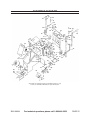
1
CURB MACHINE KIT
WITH FORMS
94634
ASSEMBLY AND OPERATING INSTRUCTIONS
Visit our website at: http://www.harborfreight.com
Read this material before using this product.
Failure to do so can result in serious injury.
Save this manual.
Copyright© 2006 by Harbor Freight Tools®. All rights reserved. No portion of this manual or any artwork
contained herein may be reproduced in any shape or form without the express written consent of Harbor
Freight Tools. Diagrams within this manual may not be drawn proportionally. Due to continuing improvements,
actual product may differ slightly from the product described herein. Tools required for assembly and service
may not be included.
For technical questions or replacement parts, please call 1-800-444-3353.
Revised Manual 09j
PRODUCT SPECIFICATIONS
Electrical Requirements
115 V~ / 60 Hz
Amperage
5.5 (Start-Up) / 3.2 (No Load)
Motor
3/4 HP; 1730 RPM
Power Switch
2-Position (ON/OFF) Slide
Power Cord
5’1” Long / 14 AWG x 3C (SJT)
Power Plug
3-Prong, Grounded
Wheel Type
Pneumatic / 8-1/2” Diameter x 2” Wide / 30 PSI Inflation Rating / 2-Ply
Concrete Opening
17-7/8” Long x 9-3/8” Wide
Overall Dimensions
42” Long x 19” Wide x 34” High
Accessories
4” x 6” Mower’s Edge Slip Form
4” x 6” Slant Style Slip Form
4” x 6” Curb Style Slip Form
Additional Features
Quick Feed Hopper with Hopper Handle
Extended Power Stroke Compaction Ram
Quick Release Slip Forms
Red Powder-Coated Exterior Housing
Unit Weight
168 lb.
SAVE THIS MANUAL
You will need this manual for the safety warnings and precautions, assembly, operating, inspection, maintenance and cleaning procedures, parts list and assembly diagram. Keep your invoice with this manual. Write the invoice number on the
inside of the front cover. Keep this manual and invoice in a safe and dry place for
future reference.
GENERAL SAFETY RULES
WARNING!
READ AND UNDERSTAND ALL INSTRUCTIONS
Failure to follow all instructions listed below may result
in electric shock, fire, and/or serious injury.
SAVE THESE INSTRUCTIONS
WORK AREA
1.
Keep your work area clean and well lit. Cluttered benches and dark areas invite accidents.
2.
Do not operate power tools in explosive atmospheres, such as in the presence of flammable liquids, gases, or dust. Power tools create sparks which may
ignite the dust or fumes.
3.
Keep bystanders, children, and visitors away while operating a power tool.
Distractions can cause you to lose control. Protect others in the work area from
debris such as chips and sparks. Provide barriers or shields as needed.
SKU 94634
For technical questions, please call 1-800-444-3353
PAGE 2
ELECTRICAL SAFETY
1.
Grounded tools must be plugged into an outlet properly installed and grounded
in accordance with all codes and ordinances. Never remove the grounding
prong or modify the plug in any way. Do not use any adapter plugs. Check with
a qualified electrician if you are in doubt as to whether the outlet is properly
grounded. If the tools should electrically malfunction or break down, grounding
provides a low resistance path to carry electricity away from the user.
2.
Double insulated tools are equipped with a polarized plug (one blade is wider
than the other). This plug will fit in a polarized outlet only one way. If the plug
does not fit fully in the outlet, reverse the plug. If it still does not fit, contact
a qualified electrician to install a polarized outlet. Do not change the plug in
any way. Double insulation
eliminates the need for the three wire grounded
power cord and grounded power supply system.
3.
Avoid body contact with grounded surfaces such as pipes, radiators, ranges,
and refrigerators. There is an increased risk of electric shock if your body is
grounded.
4.
Do not expose power tools to rain or wet conditions. Water entering a power
tool will increase the risk of electric shock.
5.
Do not abuse the Power Cord. Never use the Power Cord to carry the tools or
pull the Plug from an outlet. Keep the Power Cord away from heat, oil, sharp
edges, or moving parts. Replace damaged Power Cords immediately. Damaged Power Cords increase the risk of electric shock.
6.
When operating a power tool outside, use an outdoor extension cord marked
“W-A” or “W”. These extension cords are rated for outdoor use, and reduce the
risk of electric shock.
PERSONAL SAFETY
1.
Stay alert. Watch what you are doing, and use common sense when operating a power tool. Do not use a power tool while tired or under the influence
of drugs, alcohol, or medication. A moment of inattention while operating power
tools may result in serious personal injury.
2.
Dress properly. Do not wear loose clothing or jewelry. Contain long hair.
Keep your hair, clothing, and gloves away from moving parts. Loose clothes,
jewelry, or long hair can be caught in moving parts.
3.
Avoid accidental starting. Be sure the Power Switch is off before plugging in.
Plugging in power tools with the Power Switch on, invites accidents.
SKU 94634
For technical questions, please call 1-800-444-3353
PAGE 3
4.
Remove adjusting keys or wrenches before turning the power tool on. A
wrench or a key that is left attached to a rotating part of the power tool may result
in personal injury.
5.
Do not overreach. Keep proper footing and balance at all times. Proper footing
and balance enables better control of the power tool in unexpected situations.
6.
Use safety equipment. Always wear eye protection. Dust mask, non-skid safety
shoes, hard hat, or hearing protection must be used for appropriate conditions.
TOOL USE AND CARE
1.
Do not force the tool. Use the correct tool for your application. The correct
tool will do the job better and safer at the rate for which it is designed.
2.
Do not use the power tool if the Power Switch does not turn it on or off. Any
tool that cannot be controlled with the Power Switch is dangerous and must be
replaced.
3.
Disconnect the Power Cord Plug from the power source before making any
adjustments, changing accessories, or storing the tool. Such preventive safety
measures reduce the risk of starting the tool accidentally.
4.
Store idle tools out of reach of children and other untrained persons. Tools
are dangerous in the hands of untrained users.
5.
Maintain tools with care. Keep this tool clean. Properly maintained tools are
less likely to bind and are easier to control. Do not use a damaged tool. Tag damaged tools “Do not use” until repaired.
6.
Check for misalignment or binding of moving parts, breakage of parts, and any
other condition that may affect the tool’s operation. If damaged, have the tool
serviced before using. Many accidents are caused by poorly maintained tools.
7.
Use only accessories that are recommended by the manufacturer for your model. Accessories that may be suitable for one tool may become hazardous when used on another tool.
SERVICE
1.
Tool service must be performed only by qualified repair personnel. Service or
maintenance performed by unqualified personnel could result in a risk of injury.
2.
When servicing a tool, use only identical replacement parts. Follow instructions in the “Inspection, Maintenance, And Cleaning” section of this manual.
Use of unauthorized parts or failure to follow maintenance instructions may create
a risk of electric shock or injury.
SKU 94634
For technical questions, please call 1-800-444-3353
PAGE 4
SPECIFIC SAFETY RULES
1.
Maintain labels and nameplates on the Curb Machine. These carry important
information. If unreadable or missing, contact Harbor Freight Tools for a replacement.
2.
Always wear safety impact eye goggles, heavy work gloves, a dust mask
or respirator, non-skid shoes or boots, and a hard hat when using the Curb
Machine. Using personal safety devices reduce the risk for injury. Safety impact
eye goggles, heavy work gloves, dust masks and respirators, and hard hats are
available from Harbor Freight Tools.
3.
Maintain a safe working environment. Keep the work area well lit. Make sure
there is adequate surrounding workspace. Always keep the work area free of obstructions, grease, oil, trash, and other debris. Do not use a power tool in areas
near flammable chemicals, dusts, and vapors. Do not use this product in a damp
or wet location.
4.
Avoid unintentional starting. Make sure you are prepared to begin work before
turning on the Curb Machine.
5.
Do not force the Curb Machine. This tool will do the work better and safer at the speed and capacity for which it was designed.
6.
WARNING! Avoid accidental cuts. Keep hands and fingers away from the
Hopper and Chute areas of the Curb Machine.
7.
Never leave the Curb Machine unattended when it is plugged into an electrical
outlet. Turn off the tool, and unplug it from its electrical outlet before leaving.
8.
Make sure the Curb Machine is used on a dry, flat, level, ground surface. Avoid
steep inclines where the Curb Machine could possibly tip over.
9.
Industrial applications must follow OSHA guidelines.
10.
Never stand on the Curb Machine. Serious injury could result if the machine is
tipped over.
11.
Check the Hopper and Chute of the Curb Machine for unwanted debris before each use. Before plugging in, make a visual check to ensure the Hopper and
Chute are empty.
12.
Never attempt to remove material stuck in the moving parts of the Curb Machine when it is plugged into an electrical outlet.
13.
Allow the Motor of the Curb Machine to reach full speed before feeding concrete into the Hopper. When turning off the Curb Machine, allow the Motor to
stop on its own.
SKU 94634
For technical questions, please call 1-800-444-3353
PAGE 5
14.
Inspect the concrete before feeding it into the Hopper of the Curb Machine.
To avoid damaging the machine, make sure the concrete does not contain metal,
large rocks, or any other foreign material.
15.
Avoid accidental electrical shock. Keep all electrical connections dry and
off the ground. Do not handle the Power Switch or Power Cord Plug with
wet hands.
16.
Performance of this Curb Machine (if powered by line voltage) may vary
depending on variations in local line voltage. Extension cord usage may also
affect machine performance.
17.
Always unplug the Curb Machine from its electrical outlet before performing
any inspection, maintenance, or cleaning procedures.
18.
Keep this product and all other tools and equipment away from children and
animals. Do not allow spectators in the work area.
19.
Keep all safety guards in place and in proper working order.
20.
Use the right product for the job. There are certain applications for which this
product was designed. Do not use small equipment or tools to do the work of larger
industrial equipment and tools. Do not use this product for a purpose for which it
was not intended.
21.
WARNING! Some dust created by power sanding, sawing, grinding, drilling,
and other construction activities, contain chemicals known (to the State of California) to cause cancer, birth defects or other reproductive harm. Some examples of
these chemicals are: lead from lead-based paints, crystalline silica from bricks and
cement or other masonry products, arsenic and chromium from chemically treated
lumber. Your risk from these exposures varies, depending on how often you do this
type of work. To reduce your exposure to these chemicals: work in a well ventilated
area, and work with approved safety equipment, such as those dust masks that are
specially designed to filter out microscopic particles.
(California Health & Safety Code § 25249.5, et seq.)
22.
WARNING! People with pacemakers should consult their physician(s) before
using this product. Operation of electrical equipment in close proximity to a heart
pacemaker could cause interference or failure of the pacemaker.
23.
WARNING! The warnings and cautions discussed in this manual cannot cover
all possible conditions and situations that may occur. It must be understood by the
operator that common sense and caution are factors which cannot be built into this
product, but must be supplied by the operator.
SAVE THESE INSTRUCTIONS
SKU 94634
For technical questions, please call 1-800-444-3353
PAGE 6
GROUNDING
WARNING!
Improperly connecting the grounding wire can result in the risk of electric shock.
Check with a qualified electrician if you are in doubt as to whether the outlet is
properly grounded. Do not modify the power cord plug provided with the tool.
Never remove the grounding prong from the plug. Do not use the tool if the
power cord or plug is damaged. If damaged, have it repaired by a service facility before use. If the plug will not fit the outlet, have a proper outlet installed by
a qualified electrician.
Grounded Tools: Tools With Three Prong Plugs
1.
Tools marked with “Grounding Required” have a three wire cord and three prong
grounding plug. The plug must be connected to a properly grounded outlet. If
the tool should electrically malfunction or break down, grounding provides a low
resistance path to carry electricity away from the user, reducing the risk of electric
shock. (See Figure A.)
2.
The grounding prong in the plug is connected through the green wire inside the
cord to the grounding system in the tool. The green wire in the cord must be the
only wire connected to the tool’s grounding system and must never be attached to
an electrically “live” terminal. (See Figure A.)
3.
Your tool must be plugged into an appropriate outlet, properly installed and grounded
in accordance with all codes and ordinances. The plug and outlet should look like
those in the following illustration. (See Figure A.)
FIGURE A
FIGURE B
Double Insulated Tools: Tools With Two Prong Plugs
1.
Tools marked “Double Insulated” do not require grounding. They have a special
double insulation system which satisfies OSHA requirements and complies with
the applicable standards of Underwriters Laboratories, Inc., the Canadian Standard
Association, and the National Electrical Code. (See Figure B.)
SKU 94634
For technical questions, please call 1-800-444-3353
PAGE 7
2.
Double insulated tools may be used in either of the 120 volt outlets shown in the
preceding illustration. (See Figure B.)
Extension Cords
1.
Grounded tools require a three wire extension cord. Double Insulated tools can
use either a two or three wire extension cord.
2.
As the distance from the supply outlet increases, you must use a heavier gauge
extension cord. Using extension cords with inadequately sized wire causes a serious drop in voltage, resulting in loss of power and possible tool damage.
(See Figure C, next page.)
3.
The smaller the gauge number of the wire, the greater the capacity of the cord. For
example, a 14 gauge cord can carry a higher current than a 16 gauge cord.
(See Figure C.)
4.
When using more than one extension cord to make up the total length, make sure
each cord contains at least the minimum wire size required. (See Figure C.)
5.
If you are using one extension cord for more than one tool, add the nameplate amperes and use the sum to determine the required minimum cord size.
(See Figure C.)
6.
If you are using an extension cord outdoors, make sure it is marked with the suffix
“W-A” (“W” in Canada) to indicate it is acceptable for outdoor use.
7.
Make sure your extension cord is properly wired and in good electrical condition.
Always replace a damaged extension cord or have it repaired by a qualified electrician before using it.
8.
Protect your extension cords from sharp objects, excessive heat, and damp or wet
areas.
SKU 94634
For technical questions, please call 1-800-444-3353
PAGE 8
RECOMMENDED MINIMUM WIRE GAUGE FOR EXTENSION CORDS*
(120 or 240 VOLT)
NAMEPLATE
AMPERES
EXTENSION CORD LENGTH
(at full load)
25 Feet
50 Feet
75 Feet
100 Feet
150 Feet
0 – 2.0
18
18
18
18
16
2.1 – 3.4
18
18
18
16
14
3.5 – 5.0
18
18
16
14
12
5.1 – 7.0
18
16
14
12
12
7.1 – 12.0
18
14
12
10
-
12.1 – 16.0
14
12
10
-
-
16.1 – 20.0
12
10
-
-
-
FIGURE C
* Based on limiting the line voltage drop to five volts at 150% of the rated amperes.
Symbology
Double Insulated
Canadian Standards Association
Underwriters Laboratories, Inc.
V~
A
Volts Alternating Current
Amperes
n0 xxxx/min. No Load Revolutions per Minute (RPM)
UNPACKING
When unpacking, check to make sure all the parts shown on the Parts List on page
21 are included. If any parts are missing or broken, please call Harbor Freight Tools at
the number shown on the cover of this manual as soon as possible.
SKU 94634
For technical questions, please call 1-800-444-3353
PAGE 9
PRODUCT OVERVIEW
The Curb Machine is an electrically-driven concrete extruder.
1.
The machine operates on common household current of 115 volts.
2.
The machine produces continuous concrete edging, borders, and mower strips
without the use of form work or guide rails.
3.
The machine can produce in excess of 500 feet per hour under ideal conditions
with constant feeding.
4.
The machine can create circles with a diameter of 36 inches, and will lay the concrete product as close as 1/4 inch from an existing structure.
5.
The machine can also extrude the edging in a trench or above the ground as
needed.
PRODUCT FEATURES
1.
Body Assembly: The Body (13) includes the Hopper, Motor Enclosure, and Chute.
(See Figure E, next page.)
2.
Steering Assembly: The Steering Assembly is located at the rear of the Curb
Machine and includes the Steering Handle (46), Steering Rod (43), Wheel Bracket
(47), and rear Pneumatic Tires (9) for lateral movement of the entire unit.
(See Figure E.)
The Steering Assembly is usually centered if you are working on level ground with
no obstacles. If you are performing landscape curbing with trenches, garden areas,
etc., the Steering Assembly is moved so that the left Pneumatic Tire (9) goes in the
trench and the right Pneumatic Tire goes on the grass side. The Curb Machine can
be operated with the Steering Assembly centered or off to the left or off to the right
depending on the conditions. (See Figure E.)
3.
Front Pneumatic Tire: The Front Pneumatic Tire (9) is located on the right/front of
the Curb Machine and is only used to transport the machine. The front Pneumatic
Tire (9) should be installed upside down while curbing. To do so, loosen the Locking Knob (6). Slide the front Pneumatic Tire with its Front Tire Rod Assembly (7)
out from the Body (13) of the unit. Insert the Front Tire Rod Assembly with its front
Pneumatic Tire upside down into the Body. Then, retighten the Locking Knob.
(See Figure E, and Assy. Diagram.)
4.
Slip Forms: The Slip Forms (1A, 1B, 1C) produce the desired shape of the curb.
They come in 4 inch by 6 inch wide sizes. To install a Slip Form, align the mounting
holes in the Slip Form with the mounting holes located in the front/bottom of the
Body (13). Then secure the Slip Form in place, using the Bolts (5), Spring Washers
(4), Flat Washers (3), and Lock Nuts (2).
(See Figure E, and Assy. Diagram.)
SKU 94634
For technical questions, please call 1-800-444-3353
PAGE 10
5.
Wheel Brackets: The two Wheel Brackets (28) must be adjusted (up or down) so
that the front of the Slip Form (1A, 1B, 1C) is on the ground and the back of the Slip
Form is raised about 1/4 inch above the ground. To adjust the Wheel Brackets, turn
the two Handles (34) clockwise or counterclockwise.
(See Figure E.)
STEERING
HANDLE
(46)
BODY
(13)
HANDLE
(34)
REAR
PNEUMATIC
TIRE
(9)
REAR
PNEUMATIC
TIRE
(9)
HANDLE
(34)
WHEEL
BRACKET
(28)
WHEEL
BRACKET
(28)
POWER
SWITCH
(14)
LEVELER
(42)
FRONT PNEUMATIC TIRE
(9)
LOCKING KNOB
(6)
FRONT TIRE ROD ASSY.
(7)
SLIP FORM
(1A, 1B, 1C)
FIGURE E
6.
Power Switch: The Power Switch (14) turns the Curb Machine on and off.
(See Figure E.)
7.
Compaction Ram: The plunger, or Ram (64), pushes out the concrete product. It
should not rub on either side of the Track (63) when the Curb Machine is running.
If necessary, re-adjust the positioning of the Ram. (See Assy. Diagram.)
8.
Track: The Bearings (58) run on the Push/Pull Assembly (59) back and forth in
the Track (63). The Track should be replaced when a groove gets worn in it. The
Track should be checked and, if necessary, replaced when the Push/Pull Assembly
and/or Bearings are replaced. (See Assy. Diagram.)
9.
Motor: The Curb Machine is powered by a 115 volt, 3/4 Horsepower, electric Motor
(25). (See Assy. Diagram.)
SKU 94634
For technical questions, please call 1-800-444-3353
PAGE 11
10.
Gear Box: The Gear Box (24) is located under the Motor (25) and has a shaft
protruding out the left side. The Gear Box is factory sealed and requires no maintenance. (See Assy. Diagram.)
11.
Crank Arm: The Crank Arm (53) is connected to the Gear Box (24) shaft. The
Crank Arm has two holes in it to adjust the stroke speed and length of the Compaction Ram (64). The Crank Arm is factory preset on the longest and fastest stroke
length. The Crank Arm is attached to the Gear Box shaft with a key and keyway, as
well as set screws. Make sure the set screws remain tight. The adjustment holes
are threaded so that when you remove the nut, the bolt still needs to be threaded
in or out. (See Assy. Diagram.)
ASSEMBLY INSTRUCTIONS
NOTE:
For additional information regarding the parts listed in the following
pages, refer to the Assembly Diagram on page 22.
CAUTION! Always make sure the Power Switch (14) for the Curb Machine is
in its “OFF” position and the machine is unplugged from its electrical outlet prior
to assembling the machine, adding any accessories, or making adjustments to the
machine.
To Fill The Pneumatic Tires With Air:
The three Pneumatic Tires (9) must be properly filled with air prior to using the Curb Machine. Each tire requires 30 PSI of air pressure. Do not overfill.
MOWER’S EDGE (1A)
CURB STYLE (1C)
SLANT STYLE (1B)
FIGURE F
To Install A Slip Form:
The Curb Machine comes with three different styles of Slip Forms: The Mower’s
Edge (1A), the Curb Style (1C), and the Slant Style (1B). To install a Slip Form,
align the mounting holes in the Slip Form with the mounting holes located in the
front/bottom of the Body (13). Then secure the Slip Form in place, using the Bolts
(5), Spring Washers (4), Flat Washers (3), and Lock Nuts (2).
(See Figure F, and Assy. Diagram.)
SKU 94634
For technical questions, please call 1-800-444-3353
PAGE 12
SETTING UP THE CURB MACHINE
1.
It is recommended that you first test the Curb Machine in your driveway or garage.
Experiment by running concrete sand or mortar sand (slightly moist and without
cement) to get an idea of how to run the Curb Machine. This experiment is done
without risk since it will not set up or need to be troweled.
2.
Make sure the following parts are properly attached to the machine and adjusted:
a. The Rear Wheel Brackets (28). (See Figure E.)
b. The desired Slip Form (1A, 1B, 1C). (See Figure F.)
c. The Compaction Ram (64). (See Assy. Diagram.)
3.
Make sure the Power Switch (14) is in its “OFF” position. (See Figure E.)
4.
Plug the Power Cord (19) into a proper extension cord. Then, plug the extension
cord into the nearest 115 volt, grounded, electrical outlet. (See Assy. Diagram.)
5.
Turn the Power Switch (14) to its “ON” position. Then, check to make sure the
Compaction Ram (64) is moving back and forth in the bottom of the Hopper without
scraping or binding on either edge. By pulling the Shield (12) out of the Hopper, you
can observe the inner workings of the machine and make any necessary adjustments. ALWAYS turn the Power Switch (14) to its “OFF” position and unplug
the Curb Machine from its electrical outlet prior to making any adjustments
inside the Motor and Gear Box compartment.
(See Figure E, and Assy. Diagram.)
6.
To produce curbing, the Front Pneumatic Tire (9) should be installed upside down
or removed, leaving the front of the Slip Form (1A, 1B, 1C) on the ground.
(See Figure E.)
7.
Adjust the two Rear Wheel Brackets (28) so that the front of the Slip Form (1A, 1B,
1C) is on the ground and the back of the Slip Form is raised about 1/4 inch above
the ground. (See Figure E.)
8.
As a test, use slightly wet sand and shovel one shovel-full at a time into the Hopper.
When the sand starts to come out of the Slip Form (1A, 1B, 1C), place your foot in
front of the sand to force compaction. The Curb Machine will now start to propel
itself as it compacts the sand and extrudes a temporary curb.
9.
When finished with the experiment, make sure to turn the Power Switch (14) to its “OFF” position and unplug the machine from its electrical outlet.
(See Figure E.)
SKU 94634
For technical questions, please call 1-800-444-3353
PAGE 13
GROUND PREPARATION
1.
Make sure the ground and the trench are firm and compacted.
2.
If you have straight lines, make sure to set a string-line (not included) to keep the
Curb Machine from wandering off line.
Trenching Guide
(New Landscape Before Sod)
Mower Style Without Top Soil
FIGURE G
3.
Trench Depth
Trench Width
On Ground
10”
Mower Style With Top Soil
1”
10”
Curb/Slant Style Without Top Soil
2”
10”
Curb/Slant Style With Top Soil
3-1/2”
10”
Mower Style With Existing Sod
1-1/2”
10”
Curb/Slant Style With Existing Sod
3-1/2”
10”
The trench for the curb should be cut with a good, sharp edging shovel or square
mouth shovel (not included). The ground should be relatively dry. The trench also
needs to be wide enough to accommodate the turns and curves the Curb Machine
will have to make. (See Figure G.)
SKU 94634
For technical questions, please call 1-800-444-3353
PAGE 14
MIXING THE CONCRETE
1.
It is extremely important to have a consistent mix. If it is too wet, it will slump. If it
is too dry, it will crack.
2.
The sand should be “rough sand”, not having gravel much larger than a match head.
The sand should be free of dirt and debris.
3.
Mortar sand is recommended. Do not use silica sand. Crystalline silica contains
chemicals known (to the State of California) to cause cancer, birth defects or other
reproductive harm.
4.
The finished mix should have a consistency similar to wet sand used on the beach
to make sand castles. The following procedure is typically successful when mixing
in a mortar mixer (not included):
a. NOTE: The mix is 5 parts sand to 1 part cement.
b. With the mortar mixer running, dump in 2 five gallon buckets of sand.
c. Dump in 1/2 of a 94 pound bag of portland cement.
d. Add 3 more five gallon buckets of sand.
e. Add water until the mix reaches the proper slump. You should not be able to
squeeze water out of the mix. Do not over-mix.
OPERATING INSTRUCTIONS
Operating The Curb Machine:
1.
Wheel the Curb Machine to the starting point, and install the Front Pneumatic Tire
(9) upside down or remove. (See Figure E.)
2.
Place the front end of the Slip Form (1A, 1B, 1C) on the prepared ground where
you desire the curb to begin. (See Figure E.)
3.
Move the Rear Pneumatic Tires (9) so that the left Tire is in the trench.
(See Figure E.)
4.
Adjust the Wheel Brackets (28) so that the Curb Machine is level and the Slip Form
(1A, 1B, 1C) is at the proper height. The front of the Slip Form should be on the
ground, and the rear approximately 1/4 inch above the ground.
(See Figure E.)
5.
Make sure the Power Switch (14) is in its “OFF” position. (See Figure E.)
6.
Plug the Power Cord (19) into a proper extension cord. Then, plug the extension
cord into the nearest 115 volt, grounded, GFCI-protected electrical outlet.
NOTE: It is recommended to use a 12 or 14 gauge extension cord, as it will carry
the electrical current more efficiently than a 16 gauge extension cord.
(See Figure C, and Assy. Diagram.)
SKU 94634
For technical questions, please call 1-800-444-3353
PAGE 15
7.
Feed the concrete mix shovel by shovel into the Hopper. Do not allow the mix to
stack up in the Hopper. The Curb Machine will propel itself against the concrete
and will stop when the Hopper is empty.
8.
The operator should be aware of the following:
a. That he steers the Curb Machine where it should be going. He can see the
inside of the Slip Form (1A, 1B, 1C) through the small window above the Motor
and Gear Box. Make sure not to get the machine hung up on roots or the sod.
(See Figure E.)
b. That he keeps the Curb Machine level by constant observation of the Leveler
(42). (See Figure E.)
c. That he keeps the Slip Form (1A, 1B, 1C) at the proper height.
(See Figure E.)
Feeding The Hopper:
1.
It is not necessary or advisable to completely fill the Hopper with concrete. It is most
efficient to tap the bottom of the Hopper with a shovel at the end of the Compaction Ram (64) stroke to keep the Curb Machine moving. If the machine extrudes at
every stroke, it can produce over 500 feet per hour.
2.
It is not recommended to use a small mouth shovel to stamp down the concrete,
as it could become jammed by the Compaction Ram (64) resulting in damage to
the Gear Box or Drive Arm.
Hand Troweling:
1.
The concrete finisher should be following the Curb Machine as soon as possible
before the concrete begins to dry or set up.
2.
All of the curbing should be hand troweled. Do not over trowel. But you should go
over each section lightly at least once.
3.
Some areas, especially tight curves and circles will leave cracks in the surface which
can be filled and finished with a finishing hand trowel (not included). On tight circles,
a slightly wetter mix will help alleviate some of the cracking.
4.
When finishing the work, keep firm but light pressure on the rear of the finishing
hand trowel so that it does not gouge the concrete.
Installing Curbing In A Straight Line:
1.
Mark the installation with a string line set 1/4 inch from the desired curb edge.
2.
Run the Curb Machine with the left side (the “straight” side) along the string.
SKU 94634
For technical questions, please call 1-800-444-3353
PAGE 16
3.
After the section has been extruded, remove the string and place it in line directly
over the curb. Portions which are still not straight can be pushed into place with
the back of a shovel.
Installing Curved Curbing:
1.
It is important for the control of the Curb Machine, as well as for the protection of
the landscape, that you do not make curves too tight. Gentle curves look best, and
will allow you to be more efficient with the Curb Machine.
2.
If you have a tight curve or circle, make sure to allow for the Curb Machine to operate properly by digging the trench a little wider. The extra clearance will allow the
Slip Form (1A, 1B, 1C) to make it around the curve. (See Figure G.)
Installing Circles:
1.
The most critical part of a circle is a good radius or trench.
2.
Locate the center point of the circle. Pull a string line, and mark the outside of the
circle with spray paint or chalk. Then, dig the trench.
3.
Place the Curb Machine in the circle and as it extrudes, help pull it around so that
the back of the Slip Form (1A, 1B, 1C) doesn’t catch on the sod. Most circles smaller
than 6 feet in diameter will “break up” as you drive the machine.
4.
As you reach the end of the circle, move the Rear Pneumatic Tires (9) more towards
the middle of the circle and you will be able to extrude the concrete almost on top of
the beginning of the circle. You may wish to cut off and remove the first foot or two
of curbing, as it is likely the machine will move inward as you follow this process. As
you trowel the outside of the circle, use your hand on the inside to keep the concrete
together. Then, finish with an inside trowel (not included).
Finishing Into A Solid Object:
When installing curbing into a wall or other existing structure, the last two or three
feet will need to be finished by hand. To do so, pull the Curb Machine off. Shovel
some concrete onto the ground, hand pack it, and then shape it with a finishing
hand trowel.
Cutting Control Joints:
1.
Control joints should be cut every 3 feet. If you are in an area where there is a lot
of ground movement or freezing in the winter, control joints should be cut every 3
feet for the Mower’s Edge Style Slip Form (1A) and every 4 feet for the Curb Style
Slip Form (1C). This is done with a heavy bladed butcher knife (not included).
2.
With a butcher’s knife, cut about halfway through the concrete before it sets, pulling
the knife carefully out the front or back (usually within 15 to 30 minutes) after the
concrete is poured.
SKU 94634
For technical questions, please call 1-800-444-3353
PAGE 17
3.
It is also recommended that on sharp turns a control joint be cut on the sharpest
portion of the curve to relieve the pressure in case of ground movement. The purpose of this control joint is to allow the concrete to move with the ground rather than
forcing hairline cracks in the concrete.
Sealing:
Once the job is finished, you may wish to use a spraying canister and apply a
concrete sealer (neither included). Sealers aid the concrete in curing and seal out
water and other concrete damaging elements.
When The Job Is Finished:
1.
Make sure to unplug the Curb Machine and remove its Slip Form. Then clean the
Hopper, Chute, Slip Form, and exterior Body of the Curb Machine thoroughly with
water.
2.
Clean excess cement off the front edge of the curb, off the grass and other vegetation. If the concrete is stable, the front and back edges of the curb can be filled in
with soil.
Caring For The New Curbing:
1.
Most cement products require approximately 28 days to totally cure. During the
first 24 hours, take extra precaution to protect the cement from damage by children,
adults, vandals, and animals. During the first 24 hours, the new curbing will be “soft”.
It can be caused to crumble slightly or be scratched if sharp objects come in contact
with it or if someone or something puts excessive weight or pressure on it.
2.
Some fertilizers and chemicals will stain the new curbing. Alert those using fertilizers
and chemicals to avoid spraying on the curbing. If fertilizers and chemicals come
in contact with the new curbing, immediately hose it down thoroughly.
3.
During the first 24 to 48 hours, avoid direct sprinkler impact on the curbing. After
24 hours, a fine mist will not cause any damage.
SKU 94634
For technical questions, please call 1-800-444-3353
PAGE 18
INSPECTION, MAINTENANCE, AND CLEANING
1.
WARNING! Make sure the Power Switch (14) of the Curb Machine is in its “OFF”
position and the machine is unplugged from its electrical outlet before performing
any inspection, maintenance, or cleaning procedures.
2.
Before each use, inspect the general condition of the Curb Machine. Check for
loose screws, misalignment or binding of moving parts, cracked or broken parts,
damaged electrical wiring, and any other condition that may affect its safe operation.
If abnormal noise or vibration occurs, have the problem corrected before further
use. Do not use damaged equipment.
3.
After each use, clean the Hopper, Chute, Slip Form, and exterior Body of the Curb
Machine thoroughly with water. Do not introduce water into the Motor compartment of the machine.
4.
To replace the V-Belt, loosen the four Bolts (48) at the base of the Motor (25). Move
the Motor towards the Gear Box (24). Slip the V-Belt (20) off the two Pulleys (21,
23). Install a new V-Belt (size A500) onto the two Pulleys. Move the Motor back to
its original position. Then, firmly retighten the four Bolts.
(See Assy. Diagram.)
SKU 94634
For technical questions, please call 1-800-444-3353
PAGE 19
TROUBLESHOOTING
Problem
Possible Solution
Curb Machine will not turn on.
1. Make sure the Power Switch is in its “ON” position.
2. Make sure to use the proper size extension cord.
3. Make sure the extension cord is connected to a working, 115
volt, grounded, electrical outlet.
4. Have a qualified service technician examine the machine.
Curb Machine extrudes poorly.
1. Make sure to properly mix the cement, sand, and water.
2. Make sure the Slip Form is properly attached to the machine.
3. Make sure to properly feed the Hopper.
4. Make sure the Compaction Ram is moving freely on its Track.
5. Make sure the Crank Arm has been properly adjusted (length
and stroke of the Compaction Ram) for the job at hand.
6. Have a qualified service technician examine the machine.
SKU 94634
For technical questions, please call 1-800-444-3353
PAGE 20
PLEASE READ THE FOLLOWING CAREFULLY
THE MANUFACTURER AND/OR DISTRIBUTOR HAS PROVIDED THE PARTS LIST
AND ASSEMBLY DIAGRAM IN THIS MANUAL AS A REFERENCE TOOL ONLY. NEITHER THE MANUFACTURER OR DISTRIBUTOR MAKES ANY REPRESENTATION
OR WARRANTY OF ANY KIND TO THE BUYER THAT HE OR SHE IS QUALIFIED TO
REPLACE ANY PARTS OF THE PRODUCT. IN FACT, THE MANUFACTURER AND/
OR DISTRIBUTOR EXPRESSLY STATES THAT ALL REPAIRS AND PARTS REPLACEMENTS SHOULD BE UNDERTAKEN BY CERTIFIED AND LICENSED TECHNICIANS,
AND NOT BY THE BUYER. THE BUYER ASSUMES ALL RISKS AND LIABILITY
ARISING OUT OF HIS OR HER REPAIRS TO THE ORIGINAL PRODUCT OR REPLACEMENT PARTS THERETO, OR ARISING OUT OF HIS OR HER INSTALLATION
OF REPLACEMENT PARTS THERETO.
PARTS LIST
Part
1A
1B
1C
2
3
4
5
6
7
8
9
10
11
12
13
14
15
16
17
18
19
20
21
22
23
24
25
26
27
28
29
30
31
32
Description
4” x 6” Mower’s Edge Slip Form
4” x 6” Slant Style Slip Form
4” x 6” Curb Style Slip Form
Lock Nut (M10)
Flat Washer (#10)
Spring Washer (#10)
Bolt (M10 x 25)
Locking Knob
Front Tire Rod Assy.
Shaft Sleeve
Pneumatic Tire
Open Pin (4 x 30)
Protection Rim
Shield
Body Assy.
Power Switch
Upper Cover Plate
Grommet
Cross Head Twist Bolt (M5 x 10)
Flat Washer (#5)
Power Cord
V-Belt (A500)
Pulley
Concave Head Screw (M8 x 10)
Pulley
Gear Box
Motor
Nut (M5)
Cross Head Twist Bolt (M5 x 16)
Wheel Bracket I
Lock Nut (M6)
Washer
Bolt (M6 x 30)
Handle Pin
SKU 94634
Q’ty
1
1
1
8
10
4
4
5
1
3
3
3
2
1
1
1
1
1
10
8
1
1
1
3
1
1
1
2
2
1
2
2
2
2
Part
33
34
35
36
37
38
39
40
41
42
43
44
45
46
47
48
49
50
51
52
53
54
55
56
57
58
59
60
61
62
63
64
65
66
Description
Plastic Grip
Handle
Bolt Pin 2
Bearing (GE10E)
Turning Ball Head
Oil Cup (M6)
Nut (M10)
Stand Assy.
Cross Head Twist Bolt (M3 x 10)
Leveler
Steering Rod
Square Block
Handrail Sleeve
Steering Handle
Wheel Bracket II
Bolt (M8 x 25)
Flat Washer (#8)
Spring Washer (#8)
Lock Nut (M8)
Bolt (M10 x 35)
Crank Arm
Link Arm
Bearing (61900)
Bolt Pin 1
Bolt Pin 3
Bearing (6001)
Push/Pull Assy.
Inner Hex Screw (M8 x 55)
Lower Cover Plate
Cross Head Concave Bolt (M8 x 20)
Track
Compaction Ram
Carriage Aluminum Rivet
Aluminum Label
For technical questions, please call 1-800-444-3353
Q’ty
2
2
2
2
2
2
2
1
2
1
1
1
1
1
1
4
10
4
6
4
1
1
2
1
1
4
1
1
1
2
1
1
4
1
PAGE 21
ASSEMBLY DIAGRAM
30
31
29
32
33
34
35
28
36
38
37
32 44
43
49 39 40
10
8
27 26 9
1715
14
18
65
17 18
17 19
16
17
41
20
17
18
21
49
22
22
1A,
1B,
1C
60
24
17
6
46
47
9
53
3 2
2
8
54
55
2
58
57
10
56
58
62
59
63
49
64
2
50
51
52
22
61
5
3 4
30
31
6
9
7
37
49
29
48
11 18
8
45
34
17
13 66
11
10
25
23
12
42
39
33
51
3
5
3
4
5
NOTE:
Some parts are listed and shown for illustration purposes only,
and are not available individually as replacement parts.
SKU 94634
For technical questions, please call 1-800-444-3353
PAGE 22
Limited 1 Year warranty
Harbor Freight Tools Co. makes every effort to assure that its products meet high
quality and durability standards, and warrants to the original purchaser that this product is
free from defects in materials and workmanship for the period of one year from the date of
purchase (90 days if used by a professional contractor or if used as rental equipment). This
warranty does not apply to damage due directly or indirectly, to misuse, abuse, negligence
or accidents, repairs or alterations outside our facilities, normal wear and tear, or to lack
of maintenance. We shall in no event be liable for death, injuries to persons or property, or
for incidental, contingent, special or consequential damages arising from the use of our
product. Some states do not allow the exclusion or limitation of incidental or consequential
damages, so the above limitation of exclusion may not apply to you. This warranty is
expressly in lieu of all other warranties, express or implied, including the warranties of merchantability and fitness.
To take advantage of this warranty, the product or part must be returned to us with
transportation charges prepaid. Proof of purchase date and an explanation of the complaint must accompany the merchandise. If our inspection verifies the defect, we will either
repair or replace the product at our election or we may elect to refund the purchase price
if we cannot readily and quickly provide you with a replacement. We will return repaired
products at our expense, but if we determine there is no defect, or that the defect resulted
from causes not within the scope of our warranty, then you must bear the cost of returning
the product.
This warranty gives you specific legal rights and you may also have other rights
which vary from state to state.
3491 Mission Oaks Blvd. • PO Box 6009 • Camarillo, CA 93011 • (800) 444-3353
SKU 94634
For technical questions, please call 1-800-444-3353
PAGE 23