1
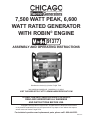
7,500 Watt Peak, 6,600
Watt Rated GENERATOR
WITH ROBIN® ENGINE
91377
ASSEMBLY AND OPERATING INSTRUCTIONS
Distributed exclusively by Harbor Freight Tools.
3491 Mission Oaks Blvd., Camarillo, CA 93011
Visit our Web site at http://www.harborfreight.com
To Help prevent serious injury OR Death,
Read and understand all warnings
and instructions before use.
Copyright © 2004 by Harbor Freight Tools®. All rights reserved. No portion of this manual
or any artwork contained herein may be reproduced in any shape or form without the express
written consent of Harbor Freight Tools.
For technical questions and replacement parts, please call 1-800-444-3353.
REV 07h
Specifications
Generator
Engine
Frame
Estimated Run Time
Overall Dimensions
Suggested Oil
Wattage @ 240V: 6,600 (rated), 7,500 (peak)
Wattage @ 125V: 6,000 (rated),
Alternator: single phase, 6 KVA. Voltage: 240 / 125
VAC, 60Hz; Nominal current: 50 amps at 125 VAC,
25 amps at 240 VAC; Outlets: 120 VAC Standard,
120 VAC twist-lock 3-prong (L530),
240/120 VAC twist-lock (L430)
Triple circuit breaker system, resettable
13.5 HP Robin Subaru®: EH41 with heavy cast
iron sleeve. EPA and Carb. approved; Four cycle
engine, 7.0 gallon gas tank, 404-cc displacement
Fuel: unleaded gasoline. Automatic “Low Oil” shut
off. Dual isolator mounts
Oil capacity: 40.56 fl. oz. Starter: Recoil & electric
Full roll cage
14.5 hours per full tank under ½ load
27-1/2 (L) x 19-3/4 (W) x 28-1/8 (H) inches
Above 32° F-SAE 30; Below 32° F-SAE 5W-30
CAUTION: This generator is not intended to power sensitive electronic equipment
without the addition of an appropriate line conditioner (sold separately).
This product requires oil and fuel to be added before starting.
Attempting to start the engine without oil will ruin the engine and void
the warranty.
Before starting the engine, refer to the engine owner’s manual for engine
maintenance information.
Save This Manual
You will need the manual for the safety warnings and precautions, assembly instructions,
operating and maintenance procedures, parts list and diagram. Keep your invoice with this
manual. Write the invoice number on the inside of the front cover. Keep the manual and
invoice in a safe and dry place for future reference.
General Safety Rules
WARNING!
READ AND UNDERSTAND ALL INSTRUCTIONS
Failure to follow all instructions listed below may result in
electric shock, fire, and/or serious injury.
SAVE THESE INSTRUCTIONS
WARNING: Before using the generator, read and understand the Robin Subaru® Engine
Operation, Maintenance, and Parts Manual. Also read the safety precautions in this
manual which should always be followed to reduce the risk of personal injury and
damage to equipment.
REV 07h
SKU 91377
For technical questions, please call 1-800-444-3353.
Page Read all instructions before installing or using this generator!
1.
Ensure installation meets all applicable safety, and local and national electrical codes.
Have installation performed by a qualified, licensed electrician and building contractor.
2.
Do not operate the generator with protective covers, access covers, or terminal box
covers removed.
3.
Disable engine-starting circuits before carrying out maintenance.
4.
Disable closing circuits and place warning notices on any circuit breakers normally
used for connection to the mains or other generators to avoid accidental closure.
5.
Do not alter or adjust any part of the generator assembled and supplied by the
manufacturer.
6.
Always follow and complete scheduled engine and generator maintenance.
7.
Do not attempt to operate the generator when conditions are unsafe. Disable the
generator until the unsafe condition is corrected.
8.
Before performing any internal generator maintenance, remove the negative lead from
the batteries to prevent accidental starting.
9.
Operate the generator only when in full compliance with relevant local and national
electrical codes and standards.
10.
Check for damaged parts. Before using the generator, any part that appears
damaged should be carefully checked to determine that it will operate properly and
perform its intended function. Check for alignment and binding of moving parts; any
broken parts; and any other condition that may affect proper operation. Any part that
is damaged should be properly repaired or replaced by a qualified technician.
11.
People with pacemakers should consult their physician(s) before using this product.
Electromagnetic fields in close proximity to a heart pacemaker could cause
interference to, or failure of the pacemaker.
12.
Guard against electric shock. Prevent body contact with grounded surfaces such as
pipes, radiators, ranges, and refrigerator enclosures.
13.
Replacement parts and accessories. When servicing, use only identical replacement
parts. Use of any other parts will void the warranty. Only use accessories intended for
use with this tool. Approved accessories are available from Harbor Freight Tools.
14.
Do not operate generator if under the influence of alcohol or drugs. Read warning
labels on prescriptions to determine if your judgment or reflexes are impaired while
taking drugs. If there is any doubt, do not operate the generator.
15.
Maintenance. For your safety, service and maintenance should be performed
regularly by a qualified technician. Never work alone on the generator.
16.
Do not alter or adjust any part of the equipment or its engine that is sealed by
the manufacturer or distributor. Only a qualified service technician may adjust
parts that may increase or decrease governed engine speed.
REV 07l
SKU 91377
For technical questions, please call 1-800-444-3353.
Page Handling and Installation Precautions
1.All electrical work, including earth-ground connection, should be completed by a
licensed electrician.
2.Any separate fuel storage generator supply facility, must be built or installed in full
compliance with relevant local, state, and federal regulations.
3.If the generator is installed indoors, exhaust fumes must be piped out of the building
using leak-free, heat-resistant piping. Pipes and silencer should not use any
flammable materials, nor should they be installed near the same. Generator exhaust
fumes should be within legal limits.
4.If the generator is installed outdoors, it must be weatherproofed and can be
soundproofed. It should not be run outdoors without weather protection to the
generator and wiring conduit.
5.Never lift the generator using the engine or alternator lifting lugs. Connect lifting
equipment to the frame of the generator.
6.
Before lifting the generator, ensure the lift rigging and supporting structure are in good
condition, and are rated to lift such a load.
7.Keep all personnel away from the suspended generator during relocating.
8.
The supporting floor should be level, and strong enough to safely hold the weight of
the generator. If the floor is not level, strong cross members should be placed under
the full length of the generator steel frame at its low side.
9.
Install sound and weather proofing only when it is not raining or snowing to avoid
trapping moisture within the generator.
Fire and Explosion Precautions
1.
Generator fuel and fumes are flammable, and potentially explosive. Use
proper fuel storage and handling procedures. Always have multiple ABC class
fire extinguishers nearby.
2.
The generator room must be adequately ventilated. Exhaust fumes must be
piped to the outdoors.
3.
Keep the generator, surrounding floors, and room clean at all times.
4.
When spills of fuel or oil occur, they must be cleaned up immediately. Dispose of fluids
and cleaning materials as per any local, state, or federal codes and regulations. Store
oil rags in a covered metal container.
5.
Never store fuel or other flammable materials near the generator.
6.
Do not smoke, or allow sparks, flames or other sources of ignition around the engine,
fuel tanks, or batteries. Fuel vapors are explosive.
7.Keep grounded conductive objects, such as tools, away from exposed, live electrical
parts and connections to avoid sparking or arcing. These events could ignite fumes or
vapors.
SKU 91377
For technical questions, please call 1-800-444-3353.
Page 8.
Do not refill the generator fuel tank of the bed frame while the engine is running.
9.
Do not operate the generator with known leaks in the fuel system.
10. Use only engine manufacturer recommended fuel and oil fluids.
Mechanical Precautions
1.
The generator is designed with guards for protection from moving parts. In any case,
care must still be taken to protect personnel and equipment from other mechanical
hazards when working around the generator.
2.
Do not operate the generator with safety guards removed. While the generator is
running, do not attempt to reach around the safety guards for maintenance or any
other reason.
3.Keep hands, arms, long hair, loose clothing, and jewelry away from pulleys, belts, and
other moving parts. Be aware that when engine parts are moving fast they cannot be
seen clearly.
4.
When working in and around the generator always wear protective clothing including
gloves, ANSI approved safety goggles and safety hat.
Noise Precautions
The generator can product high noise levels. Prolonged exposure to noise levels above
85 dBA is hazardous to hearing. Always wear ear protection when operating or working around
the generator when it is running.
Electrical Precautions
1.
All connections and conduit from the generator to the load must only be
installed by trained and licensed electricians, and in compliance with all
relevant local, state, and federal electrical codes and standards, and other
regulations where applicable.
2.
The generator must be earth-grounded in accordance with all relevant electrical codes
and standards before operation.
3.
Before performing any maintenance or connecting or disconnecting any electrical load
connections, the engine must be disabled.
4.
Do not attempt to connect or disconnect load connections while standing in water, or
on wet or soggy ground.
5.
Do not touch electrically energized parts of the generator and interconnecting cables
or conductors with any part of the body, or with any non-insulated conductive object.
6.
Connect the generator only to a load or electrical system that is compatible with the
electrical characteristics and rated capacity of the generator.
7.
Before servicing equipment powered by the generator, disconnect the equipment from
its power input.
SKU 91377
For technical questions, please call 1-800-444-3353.
Page 8.Keep all electrical equipment clean and dry. Replace any wiring where the insulation
is cracked, cut, abraded or otherwise degraded. Replace terminals that are worn,
discolored, or corroded. Keep terminals clean and tight.
9.Insulate all connections and disconnected wires.
10. Use only Class BC or Class ABC fire extinguishers on electrical fires.
Electric Generator Safety Precautions and Warnings
Carbon Monoxide Inhalation Hazard
1.
This engine-run generator must never be used indoors, in a house, or
any other sealed structure. Carbon monoxide is produced during
operation and is deadly in a closed environment. Early signs of carbon
Monoxide poisoning resemble the flu, with headaches, dizziness, or
nausea. If you have these signs get fresh air immediately.
2.
The Generator produces electrical current. Improper use can result in electrocution,
injury or death. Only a qualified technician should service or repair this generator.
3.
The Generator was designed to be used in a dry area. Do not expose to rain, snow,
sleet, or damp conditions. Damage to the Generator could occur. Moisture can carry
electrical current and could cause electrocution.
4.If the Generator is connected to a building, home, business, or any other electrical
circuit normally fed by utility power, steps must be taken to ensure that the Generator
output and the utility power are positively isolated. Failure to isolate the systems will
result in Generator damage. It could also result in personal injury or death to those
working around these circuits. Any connection in this regard must only be done by a
licensed electrician.
5.Avoid damaging the Generator by exceeding its rated capacity. The total electrical
loads at each outlet must be added to determine the total electrical load. If the
electrical appliance does not list the wattage rating, you can calculate it by multiplying
amps times voltage (amps x voltage = watts).
6.
Do not tamper with the engine-governed speed. The Generator operates at a
nominal speed of 3600 RPM. Increases in speed could damage rotating parts of the
Generator. Slower speeds could damage the Generator or appliances connected to
the Generator due to low voltage.
7.Always follow national and local safety codes.
8.
Do not start the Generator with appliances connected and turned on.
9.
Give the Generator at least two feet of space to dissipate heat.
10. Properly ground the Generator. The National Electrical Code requires that the Generator
frame be properly grounded to earth. This should be done by a licensed electrician.
(Refer to Grounding on the next page.)
11.Never handle electrically charged extension cords while standing in water.
SKU 91377
For technical questions, please call 1-800-444-3353.
Page 12.Only use 3-prong (125 VAC) or 4-prong (240 VAC), grounded extension cords.
Warning: The warnings, cautions, and instructions discussed in this instruction
manual cannot cover all possible conditions and situations that may occur. It must be
understood by the operator that common sense and caution are factors which cannot
be built into this product, but must be supplied by the operator.
First Aid for Electric Shock
1.
Do not touch the victim’s skin with bare hands until the source of the electricity has
been turned off.
2.
Turn the generator off.
3.
Pull the plug or hot cable away from the victim using an insulated material.
4.Stand on dry insulating material and pull the victim clear of the conductor, preferably
using insulated material such as dry wood or an insulated hook.
5.Once the victim is free of the electric current, check for breathing. If not breathing,
perform CPR and keep the victim warm. Have someone call the paramedics.
Grounding
Warning: This generator must be grounded to earth ground before using. Refer to the
photo at the top of the next page.
WARNING
Improperly connecting the grounding wire can result in the risk of electric
shock. Check with a qualified electrician if you are in doubt as to whether the outlet is
properly grounded. Do not modify the power cord plug provided with the tool - Never
remove the grounding prong from the plug. Do not use the tool if the power cord or
plug is damaged. If damaged, have it repaired by a service facility before use. If the
plug will not fit the outlet, have a proper outlet installed by a qualified electrician.
Generator Ground
Terminal
Connect a # 6 AWG solid copper wire from the ground terminal to an earth grounding point.
Grounded Tools: Tools with Three Prong Plugs
1.
Tools marked with “Grounding Required” have a three wire cord and three prong
grounding plug. The plug must be connected to a properly grounded outlet. If the tool
SKU 91377
For technical questions, please call 1-800-444-3353.
Page should electrically malfunction or break down, grounding provides a low resistance
path to carry electricity away from the user, reducing the risk of electric shock. (See
Figure A.)
2.
The grounding prong in the plug is connected through the green wire inside the cord
to the grounding system in the tool. The green wire in the cord must be the only
wire connected to the tool’s grounding system and must never be attached to an
electrically “live” terminal. (See Figure A.)
3.
Your tool must be plugged into an appropriate outlet, properly installed and grounded
in accordance with all codes and ordinances. The plug and outlet should look like
those in the following illustration. (See Figure A.)
Figure A
Figure B
Double Insulated Tools: Tools with Two Prong Plugs
4.
Tools marked “Double Insulated” do not require grounding. They have a special
double insulation system which satisfies OSHA requirements and complies with the
applicable standards of Underwriters Laboratories, Inc., the Canadian Standard
Association, and the National Electrical Code. (See Figure B above.)
5.
Double insulated tools may be used in either of the 120 volt outlets shown in the
following illustration. (See Figure B above.)
Extension Cords
1.
Grounded tools require a three wire extension cord. Double Insulated tools can use
either a two or three wire extension cord.
2.As the distance from the supply outlet increases, you must use a heavier gauge
extension cord. Using extension cords with inadequately sized wire causes a serious
drop in voltage, resulting in loss of power and possible tool damage. (See Table A.)
3.
The smaller the gauge number of the wire, the greater the capacity of the cord. For
example, a 14 gauge cord can carry a higher current than a 16 gauge cord. (See
Table A.)
4.
When using more than one extension cord to make up the total length, make sure
each cord contains at least the minimum wire size required. (See Table A.)
5.If you are using one extension cord for more than one tool, add the nameplate
amperes and use the sum to determine the required minimum cord size. (See Table
A.)
SKU 91377
For technical questions, please call 1-800-444-3353.
Page 6.
If you are using an extension cord outdoors, make sure it is marked with the suffix “WA” (“W” in Canada) to indicate it is acceptable for outdoor use.
7.
Make sure your extension cord is properly wired and in good electrical condition.
Always replace a damaged extension cord or have it repaired by a qualified electrician
before using it.
8.
Protect your extension cords from sharp objects, excessive heat, and damp or wet
areas.
RECOMMENDED MINIMUM WIRE GAUGE FOR EXTENSION CORDS* (120/240 VOLT)
NAMEPLATE
AMPERES
EXTENSION CORD LENGTH
(at full load)
25 Feet
50 Feet
75 Feet
100 Feet
150 Feet
0 – 2.0
18
18
18
18
16
2.1 – 3.4
18
18
18
16
14
3.5 – 5.0
18
18
16
14
12
5.1 – 7.0
18
16
14
12
12
7.1 – 12.0
18
14
12
10
-
12.1 – 16.0
14
12
10
-
-
16.1 – 20.0
12
10
-
-
-
TABLE A
* Based on limiting the line voltage drop to five volts at 150% of the rated amperes.
Symbology
Double Insulated
Canadian Standards Association
Underwriters Laboratories, Inc.
SKU 91377
V~
A
Volts Alternating Current
Amperes
No Load Revolutions per Minute
n0 xxxx/min. (RPM)
For technical questions, please call 1-800-444-3353.
Page Unpacking
When unpacking, check to make sure that all the parts are included. Refer to the Assembly
section, and the Assembly Drawing and Parts List at the end of this manual.
If any parts are missing or broken, please call Harbor Freight Tools at the number on the
cover of this manual as soon as possible.
Operating Instructions
Generator Engine Controls
Gas Valve
Engine On/Off Switch
Choke
Starter Pull Cord
Generator Electrical Controls and Outlets
30A Circuit Breaker
Reset Button
30A Circuit Breaker
Reset Button
20A Circuit Breaker
Reset Button
240/120 VAC Outlet
Twist Lock
NEMA # L430
120 VAC Outlet
3-Prong Standard
120 VAC Outlet
3-Prong Locking NEMA # 530
REV 07h
SKU 91377
For technical questions, please call 1-800-444-3353.
Page 10
Generator Setup and Cable Connections
1.
Place the Generator outdoors where it will be used.
This should be on a flat surface and away from flammable materials. Do not allow
the Generator to get wet. If used indoors, the area must be well ventilated to allow
dissipation of exhaust fumes.
2.
Fill the Gas Tank (outdoors) with up to seven gallons of unleaded gasoline. Do not
top-off tank.
3.Add 40 oz. of oil to the Engine by removing either Dip Stick, and adding through its
hole.
If the area temperature is above freezing, use F-SAE 30 weight oil. If below freezing,
use F-SAE 5W-30 weight oil. Use a siphon to avoid spilling the oil. Check the oil level
with the Dip Stick. It should be up to the “Full” mark. Carefully screw the plastic Dip
Stick back into the metal Engine crankcase to avoid stripping the plastic threads on
the Dip Stick.
4.
Plug in the extension cords or appliances, making sure that the appliance (loads) are
turned off.
Refer to the section on Extension Cords on page 9. Do not overload the Generator.
Calculate the total wattage of the appliances. The Generator has a maximum power
output of 6,600 watts (total from all outlets being used).
Warning: If the Generator will be used to replace facility power in times of outages, the
facility power input must be isolated. Refer to the Electric Generator Safety Precautions
on page 6. These connections must only be made by a licensed electrician.
Starting the Generator
This product contains or, when used, produces a chemical known to
the State of California to cause cancer and birth defects or other reproductive harm.
(California Health & Safety Code § 25249.5, et seq.)
1.Open the Gas Valve by turning it counterclockwise until it stops. Refer to the
Generator Engine Controls photo on page 10.
2.
Turn the Engine On/Off Switch to the On position.
3.Verify all connected appliances are turned off.
4.If the Engine is cold, pull the Choke Button out. Otherwise, continue with the next
step.
5.
NOTE: DO NOT ATTEMPT TO ADJUST THE ENGINE’S THROTTLE! This engine
uses a governor device to automatically control the engine’s speed. If the
throttle is adjusted, it may result in decreased efficiency and/or damage to the
unit.
6.
Gently pull the Start Pull Cord until it engages. Then pull it hard and all the way out.
SKU 91377
REV 07h
For technical questions, please call 1-800-444-3353.
Page 11
The Engine should start. Try again if it does not start. Refer to the Robin Subaru®
Operator’s Manual under Troubleshooting if problems persist. Let the engine run for
five minutes to warm up.
7.
Push in the Choke Button.
8.
Begin to turn on the connected appliances.
The Engine governor will regulate the throttle automatically depending on the
electrical load applied to the generator. If electricity to one of the outlets stops, it could
be that the circuit was overloaded. Check the appliance(s) wattage, then push in on
the corresponding Circuit Breaker Reset Button to resume power.
9.
When you are finished using the Generator:
- Turn off, then unplug all appliances.
- Stop the motor driver by turning the Engine On/Off switch to the Off position.
-Turn the Gas Valve clockwise and close it completely.
INSPECTION, MAINTENANCE, AND CLEANING
Disconnect the wire to the Spark Plug of the Engine before performing
any inspection, maintenance, or cleaning procedures.
1.
Before each use, inspect the general condition of the Generator. Check for loose
screws, misalignment or binding of moving parts, cracked or broken parts, damaged
electrical wiring, and any other condition that may affect its safe operation. If
abnormal noise or vibration occurs, have the problem corrected before further use. Do
not use damaged equipment.
2.
Periodically recheck all nuts, bolts, and screws for tightness.
3.Store in a clean and dry location.
4.
For Engine maintenance and troubleshooting, refer to the Robin Subaru® Engine
Operator’s Manual.
5.After the Engine has cooled down, remove the remaining gasoline into a gasoline
container before storing the unit.
6.
After the first five hours of use, drain and replace the Engine oil. After that, replace the
oil after every 25 hours of use.
REV 04k
SKU 91377
For technical questions, please call 1-800-444-3353.
Page 12
Parts List
Part
1
2
3
5
6
7
10
11
12
13
14
15
16
17
18
19
22
23
24
25
26
27
Code #
EH410GE
31227
30010102
30060802
15051079
30050202
15190240
45040103
15170101
30070102
15050104
15050101
10160102
70130202
60130703
60020206
60020304
60160703
60150718
60150713
60150725
60030109
Description
GA ENGINE, 13.5 HP, ROBIN
SINGLE PHASE ALTERNATOR, 6 KVA
MOUNTING FLANGE
END COVER
TUBE FRAME
FUEL TANK, 7 GAL
CONTROL PANEL
CONTACT BOX
HEAT SHIELD
FUEL CAP
BRACKET
BRACKET
RUBBER SUPPORT
5/16”, BIG BUMPERS
1/4” X 1” HEX HEAD TAPPING SCREW
5/16” SEQUENCE With PLAIN WASHER
5/16” HELICAL SPRING LOCK WASHER
5/16” HEX NUT
5/16” X 1 1/2” HEX BOLT
5/16” X 1/2” HEX BOLT
3/8” X 1” NC HEX BOLT
GALVANIZED TIE ROD
Qty.
1
1
1
1
1
1
1
1
1
1
1
2
3
4
6
6
8
5
2
2
4
1
NOTE: Some parts are listed and shown for illustration purposes only
and are not available individually as replacement parts.
SKU 91377
For technical questions, please call 1-800-444-3353.
Page 13
Assembly Drawing
PLEASE READ THE FOLLOWING CAREFULLY
THE MANUFACTURER AND/OR DISTRIBUTOR HAS PROVIDED THE PARTS DIAGRAM IN THIS
MANUAL AS A REFERENCE TOOL ONLY. NEITHER THE MANUFACTURER NOR DISTRIBUTOR MAKES
ANY REPRESENTATION OR WARRANTY OF ANY KIND TO THE BUYER THAT HE OR SHE IS QUALIFIED
TO MAKE ANY REPAIRS TO THE PRODUCT OR THAT HE OR SHE IS QUALIFIED TO REPLACE ANY PARTS
OF THE PRODUCT. IN FACT, THE MANUFACTURER AND/OR DISTRIBUTOR EXPRESSLY STATES THAT
ALL REPAIRS AND PARTS REPLACEMENTS SHOULD BE UNDERTAKEN BY CERTIFIED AND LICENSED
TECHNICIANS AND NOT BY THE BUYER. THE BUYER ASSUMES ALL RISK AND LIABILITY ARISING
OUT OF HIS OR HER REPAIRS TO THE ORIGINAL PRODUCT OR REPLACEMENT PARTS THERETO, OR
ARISING OUT OF HIS OR HER INSTALLATION OF REPLACEMENT PARTS THERETO.
SKU 91377
For technical questions, please call 1-800-444-3353.
Page 14
Wiring Diagram
Note: Only a licensed electrician should perform electrical repairs
on this generator.
Black
White
Black
Green
SKU 91377
For technical questions, please call 1-800-444-3353.
Page 15
SCHEMATIC DRAWING
RE-STARTER SWITCH WITH GFCI
E
D
5
7
D
6
4
9
3
F
1
B
2
A
B
11
12
C
G
10
Parts List
Item
QTYDescription
A
1Inlet 20A
B
1Inlet 30A 125/250V
C
1Inlet 30A 129
Blue
D
2Re-starter 20A
Red
E
1Re-starter 25A 125/250V
F
1
Wiring Harness
Black
G
1
Wiring Type
125
Cable of Caliber 12 White
200
Cable of Caliber 12 Black
105
Cable of Caliber 12 Green
Black
65
Cable of Caliber 12 Red
Black
55
Cable of Caliber 12 Blue
4
Plug In Terminal
Black
1
Plug Out Terminal 12-10
1
Terminal 3/10 cal 14
1
Terminal 1/4 cal 12
1Adapter Terminal
SKU 91377
Assembly of Cable & Terminals
White
Black
Black
White
White
Green
Green
For technical questions, please call 1-800-444-3353.
Page 16