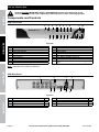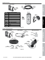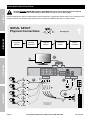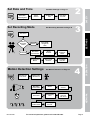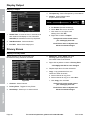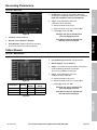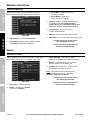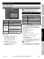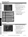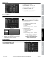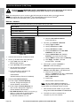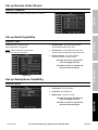
1
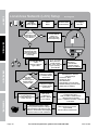
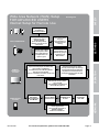
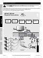
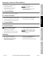
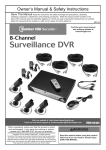
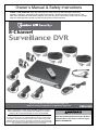
Owner’s Manual & Safety Instructions
Save This Manual Keep this manual for the safety warnings and precautions, assembly,
operating, inspection, maintenance and cleaning procedures. Write the product’s serial number in the
back of the manual near the assembly diagram (or month and year of purchase if product has no number).
Keep this manual and the receipt in a safe and dry place for future reference.
8-Channel
Surveillance DVR
Visit our website at: http://www.harborfreight.com
Email our technical support at: [email protected]
ITEM 61229
When unpacking, make sure that the product is intact
and undamaged. If any parts are missing or broken,
please call 1-800-444-3353 as soon as possible.
Copyright© 2013 by Harbor Freight Tools®. All rights reserved.
No portion of this manual or any artwork contained herein may be reproduced in
any shape or form without the express written consent of Harbor Freight Tools.
Diagrams within this manual may not be drawn proportionally. Due to continuing
improvements, actual product may differ slightly from the product described herein.
Tools required for assembly and service may not be included.
Read this material before using this product.
Failure to do so can result in serious injury.
Save this manual.
Table of Contents
Safetye��������������������������������������������������������� 3
DVR Operating Instructions..................... 2
Specifications............................................ 5
Search Recordings................................... 25
Set up - Before Use................................... 6
Backup Recordings.................................. 26
Quick Start Guide Flow Charts................. 8
Format Drives........................................... 27
DVR Equipment Connections.................. 12
PTZ Camera............................................. 27
DVR Settings............................................. 15
Local Area Network Setup....................... 28
Pop-Up Menu........................................... 15
Set up Remote Video Stream................... 29
Main Menu................................................ 15
Set up Email Capability............................ 29
Main Menu Map........................................ 16
Set up Smartphone Capability.................. 29
Main Settings............................................ 17
Wide Area Network Setup........................ 30
Recording Schedule................................. 18
Software.................................................... 31
Motion Detection...................................... 19
DVR Client................................................ 31
Users........................................................ 20
Video Player............................................. 32
System Information.................................. 21
MAC Record Player.................................. 32
Display Settings........................................ 21
AVI Generator........................................... 32
Display Output.......................................... 22
Smartphone.............................................. 32
Privacy Zones........................................... 22
Maintenance Instructions........................ 33
Recording Parameters............................. 23
Troubleshooting....................................... 34
Video Stream............................................ 23
Parts List................................................... 35
Maintain Hard Drive.................................. 24
Warranty.................................................... 36
Alerts........................................................ 24
WARNING SYMBOLS AND DEFINITIONS
This is the safety alert symbol. It is used to alert you to potential
personal injury hazards. Obey all safety messages that follow
this symbol to avoid possible injury or death.
Indicates a hazardous situation which, if not avoided,
will result in death or serious injury.
Indicates a hazardous situation which, if not avoided,
could result in death or serious injury.
Indicates a hazardous situation which, if not avoided,
could result in minor or moderate injury.
Addresses practices not related to personal injury.
Important Safety Information
Read all safety warnings and instructions.
Failure to follow the warnings and instructions may result in electric shock, fire and/or serious injury.
Save all warnings and instructions for future reference.
Page 2
For technical questions, please call 1-800-444-3353.
Item 61229
Installation Precautions
2. Install only according to these instructions.
Improper installation can create hazards.
3. Do not overreach when installing this product.
Keep proper footing and balance at all times.
This enables better control in unexpected situations.
4. Wear ANSI-approved safety goggles
during installation.
5. Keep installation area clean and well lit.
Safety
1. Check federal, state and local surveillance laws
before installing video
and/or audio surveillance equipment.
6. Keep children and bystanders out of
the area during installation.
7. Do not install when tired or when under the
influence of alcohol, drugs or medication.
Use Precautions
2. Use as intended only.
4. Maintain product labels and nameplates.
These carry important safety information.
If unreadable or missing, contact
Harbor Freight Tools for a replacement.
3. Do not modify.
Electrical Safety
1. Power Adapter plugs must match
the outlet. Never modify the plug in
any way. Unmodified plugs and matching
outlets will reduce risk of electric shock.
2. Do not expose DVR unit to rain or wet
conditions. Water entering the DVR will
increase the risk of electric shock.
3. Do not abuse the cord. Never use the cord
for carrying, pulling or unplugging the
power tool. Keep cord away from heat, oil,
sharp edges or moving parts. Damaged or
entangled cords increase the risk of electric shock.
Settings
1. This product is not a toy. Do not allow
children to play with or near this item.
Have your DVR equipment serviced by a qualified repair person using only identical replacement parts.
This will ensure that the safety of the equipment is maintained.
Camera Safety Warnings
1. To prevent electric shock, do not attempt
to disassemble Camera. There are
no serviceable parts inside.
2. Use supplied Power Adapter only.
5. Handle Camera with care. Camera could be
damaged by improper handling or storage.
Network
3. Do not expose the Power Adapter to rain
or wet conditions. Water entering the Power
Adapter will increase the risk of electric shock.
4. Do not abuse the Power Adapter cord. Never
use the cord for unplugging the plug from the
outlet. Keep cord away from heat, oil, sharp
edges or moving parts. Damaged or entangled
cords increase the risk of electric shock.
Operation
Service
Item 61229
For technical questions, please call 1-800-444-3353.
Page 3
DVR Safety Warnings
1. Maintain adequate airflow around DVR.
2. Use supplied Power Adapter only.
Safety
3. Do not expose the Power Adapter or DVR
console to rain or wet conditions. Water
entering the Power Adapter or DVR console
will increase the risk of electric shock.
4. Do not abuse the Power Adapter cord. Never
use the cord for unplugging the plug from the
outlet. Keep cord away from heat, oil, sharp
edges or moving parts. Damaged or entangled
cords increase the risk of electric shock.
5. Maintain labels and nameplates on the unit.
These carry important safety information. If
unreadable or missing, contact Harbor
Freight Tools for a replacement.
6. WARNING: Handling the cord on this product will
expose you to lead, a chemical known to the State
of California to cause cancer, and birth defects or
other reproductive harm. Wash hands after handling.
(California Health & Safety Code § 25249.5, et seq.)
7. The warnings, precautions, and instructions
discussed in this instruction manual cannot
cover all possible conditions and situations
that may occur. It must be understood by the
operator that common sense and caution are
factors which cannot be built into this product,
but must be supplied by the operator.
Settings
Save these instructions.
Grounding
Operation
To prevent electric shock and death from
incorrect grounding wire connection:
Check with a qualified electrician if you are in doubt as to whether the outlet is properly
grounded. Do not modify the power cord plug provided with the tool. Never remove the
grounding prong from the plug. Do not use the tool if the power cord or plug is damaged. If damaged, have
it repaired by a service facility before use. If the plug will not fit the outlet, have a proper outlet installed by
a qualified electrician.
1. The included Power Adapters do
not require grounding.
2. The Power Adapters may be used in
either of the 120 volt outlets shown in the
preceding illustration. (See Figure A.)
Figure A: Outlets for 2-Prong Plug
Extension Cords
Note: Do not use an extension cord with the Power Adapters.
Network
Symbology
Double Insulated
Canadian Standards Association
Underwriters Laboratories, Inc.
Page 4
V
~
A
Volts
Alternating Current
Amperes
For technical questions, please call 1-800-444-3353.
Item 61229
Specifications
Hard Drive
500 GB
Video Standard
NTSC / PAL
Video Codec
H.264
Video I/O
Audio Codec
Audio I/O
Recording
Safety
DVR
Input: 8 BNC
Output: 2 BNC / 1 VGA
G.711
Input: 1 RCA
Output: 1 RCA
Resolution
CIF: 352 x 240;
HD1: 704 x 240;
D1: 704 x 480
Manual / Schedule / Motion Detection / Remote
Motion Detection
Selectable Area and Sensitivity Detection
PTZ Interface
RS485 - Supports Pelco-D/P camera (sold separately)
Network Interface
RJ-45 10m/100m Ethernet Interface
USB Interface
USB 2.0
DVR Input Rating
12VDC / 2A
Operating Temperature
32º - 131ºF
SETtings
Frame Rate Up to 30 fps each channel
Recording Mode
2 Cameras with fixed 6 mm lenses
2 Cameras with fixed 3.6 mm lenses
Horizontal Resolution
400 TVL
Effective Pixels
648H x 488V
Night Vision Type
Infrared LEDs with Low Light Sensor
Image Type
Daylight: Color
Infrared: Black & White
Infrared Wavelength
850nm
Infrared Distance
30 ft. (indoors)
Ingress Protection Rating
IP65 - Protected from low pressure water jets
Video Connector
BNC
Camera Input Rating
12VDC / 500 mA
Cable Length
60 ft.
Operating Temperature
14° - 122°F
Network
Lens Types
Operation
Cameras
Item 61229
For technical questions, please call 1-800-444-3353.
Page 5
Set up - Before Use:
Read the entire Important Safety Information section at the beginning of this
manual including all text under subheadings therein before set up or use of this product.
Safety
Components and Controls
DVR Front Panel
1
4
3
2
5
6
7
8
9
11 12 13 14 15 16
10
17 18 19
SETtings
Figure B
1
2
3
4
5
6
7
8
9
10
Green Power Indicator
Remote Control IR Receiver
Red Hard Disk Drive Activity Indicator
Search Recordings
Mute
Previous Channel
Next Channel
Toggle 4 and 9 Screen Displays
Menu Up / PTZ Up
PTZ Control Mode
11
12
13
14
15
16
17
18
19
Rewind / Activate Controls
Pause
Play
Fast Forward
Stop
Start Manual Recording
Open Menu / Escape / PTZ Left
Menu Down / PTZ Down
Confirm Selection / Edit Selected Setting / PTZ
Right
Note: Controls for PTZ mode are italicized.
Operation
DVR Back Panel
3
2
1
6
5
7
8
4
9
Figure C
Network
1
2
3
4
5
BNC Video Input
RCA Audio Input
RJ45 LAN Ethernet Port
12VDC Power Input
BNC Video Output
Page 6
8
1
1
1
2
6
7
8
9
RCA Audio Output
VGA Port
USB 2.0 Port
RS485 PTZ Connector
For technical questions, please call 1-800-444-3353.
1
1
2
1
Item 61229
DVR Accessories
Power Adapter
BNC to RCA Cable
RCA (to
Monitor)
BNC
(to DVR)
Safety
Power
(to DVR)
Remote
Mouse
Note:
2 AAA
batteries
included.
SETtings
Remote Control Functions
1-8
Select Channel
ALL
Toggle 4 and 9 Screen Displays
MENU
Open Menu
MUTE
Mute
SUBMENU Open Pop-Up Menu
▲
Menu Up
▼
Menu Down
◄
Menu Left
►
Menu Right
SEL
Confirm Selected Operation
◄◄
Rewind
►
Play / Search Records
►►
Fast Forward
●
Record
ll
Pause
Stop
■
Figure D
Camera and Accessories
Power Splitter
Power
(to Splitter)
Mounting Hardware
Power
(from Adapter)
Operation
Power Adapter
Screws
Power
(to Cables)
Anchors
Camera
Cable - 60 ft.
Hood
Video
(to Cable)
Lens
Power
(from Cable)
Item 61229
Power
(to Camera)
Video
(to DVR)
Power
(from Splitter)
Network
Video
(from Camera)
Figure E
For technical questions, please call 1-800-444-3353.
Page 7
Quick Start Guide Flow Charts
Read the entire Important Safety Information section at the beginning of this manual
including all text under subheadings therein before set up or use of this product.
Safety
Use the following flow charts to help make the cable connections, navigate the system and set up or change the unit
settings. Refer to the individual setup sections in this manual for detailed instructions on specific tasks.
INITIAL SETUP
Physical Connections
SETtings
A
B
D
C
Connect
Cameras
Connect
Monitor
1
See Page 12
E
Connect
Mouse
Connect
Power
Mount
Cameras
A
D1
Video Output
Operation
BNC/RCA
VGA
Video Input
B1
B
USB Port Power Input
B3
C
D2
B2
B1
B4
D5
B2
B1
Network
D
D3
B2
B1
B2
Page 8
B5
D4
Note: Monitor and
Surge Protector
sold separately.
For technical questions, please call 1-800-444-3353.
Item 61229
Set Date and
Time
Set Recording Mode
Click Apply
then OK
See Recording Schedule on Page 18
Press REC on
front of DVR red light will
flash
Which
Recording
mode?
Manual
Scheduled
In DVR
Main Menu
select Record
Select
Schedule
Select Channel
and Day of
Week
Select boxes
for Normal and
Motion
Repeat for all
Days and all
Channels
Click Apply
then OK
Motion Detection Settings
Set Date and
Time above
Item 61229
3
SETtings
Set Date and
Time above
2
Safety
Select
General
See Motion Detection on Page 19
Set Recording
Mode above
In DVR
Main Menu
Select Alarm
Select
Motion
Select
Channel
Select Area
Set Sensitivity
Level
Select which
Channels
will record
Set Buzzer for
audible alarm
Click Apply
then OK
For technical questions, please call 1-800-444-3353.
4
Network
In DVR
Main Menu
Select System
See Main Settings on Page 17
Operation
Set Date and Time
Page 9
Safety
Local Area Network (LAN) Setup
In DVR
Main Menu
Select System
Do you have a
Windows® PC with
Internet Explorer®
and a Router?
Select
Users
YES
See Page 28
Set User Name
and Password
Click Apply
then OK
Connect DVR to
Router via
Ethernet Cable
(Sold Separately)
SETtings
NO
STOP
Ensure you have a
Windows® PC with
Internet Explorer®
and a Router before
proceeding.
Ethernet
Connection
From DVR Main Menu
select
Network > Network
Type = Static
Operation
NO
Create New IP
Address:
Are last 3 digits of
Default Gateway
between 0-99?
YES
Click Apply then OK
to save changes.
Click Exit, DVR will prompt
restart. Click OK.
Network
@
Page 10
On PC, go to Start
Menu, click Run.
In DOS window
type “cmd”, click OK.
type “ipconfig”
press ENTER
Change last 3 digits
to a number between
200 and 255
Change last 3 digits
to a number between
100 and 255
After restart,
on DVR go to
Network > Network
to view settings.
Allow ActiveX Control to install.
You may need to adjust the settings in
Internet Explorer® by adding the http
address to Trusted Sites and modifying
ActiveX controls to allow installation.
Find the Router’s LAN
Write down:
1. Subnet Mask
2. Default Gateway
(Router’s IP Address)
In DVR Network > Network
change settings:
1. Client Port: 3000
2. HTTP Port: 3001
3. New IP Address
4. Subnet Mask you wrote down
5. Default Gateway you wrote down
6. DNS1 same as Gateway
Open Internet Explorer®.
In address bar, type in
DVR’s IP Address and HTTP Port:
http://xxx.xxx.xxx.xxx:3001
(where x = IP Address and 3001 = HTTP Port)
Press Enter.
After ActiveX Control installs,
Log in to DVR
with User Name and Password.
For technical questions, please call 1-800-444-3353.
Item 61229
Wide Area Network (WAN) Setup
FOR ADVANCED USERS
Internet Setup for Remote Use
Safety
See Page 30
Set up LAN
according to
instructions above.
REMOTE
COMPUTER
ACCESS
Set start port to 3000
and end port to 3002.
Set up both UDP and
TCP protocols if the
option is given.
SETtings
@
Log in to the Router
and go to
Port Forwarding or
Applications and
Gaming.
Find the Router’s IP
Address by going to
whatsmyip.com.
Write it down.
On remote computer,
Open Internet Explorer®. In address bar,
type in Router’s IP Address
and HTTP Port (from LAN Setup above):
http://xx.xxx.xxx.xxx:3001
(where x = IP Address and 3001 = HTTP Port)
Press Enter.
Allow ActiveX Control to install.
You may need to adjust the settings
in Internet Explorer® by adding the
http address to Trusted Sites and
modifying ActiveX controls to allow
installation.
Operation
PORT FORWARDING
Open Internet Explorer®.
In address bar, type in
Default Gateway
(from LAN Setup above).
Example: xxx.xxx.xxx.xxx
Press Enter.
After ActiveX Control installs,
Log in to DVR
with User Name and Password
(from LAN Setup above).
Set User Name
and Password
Set Mobile Port
to 3002
Click Apply
then OK
Network
SMARTPHONE
ACCESS
In DVR
Main Menu
Select Network
then Mobile
Insert supplied CD
into computer and look in
Mobile Software
folder for instructions.
Item 61229
For technical questions, please call 1-800-444-3353.
Page 11
DVR Equipment Connections
Read the entire Important Safety Information section at the beginning of this manual
including all text under subheadings therein before set up or use of this product.
Safety
Check federal, state and local surveillance laws before installing video and/or audio surveillance equipment.
Connect and test all equipment and camera locations before installing cameras.
Use a surge protector (sold separately) to protect equipment.
1
INITIAL SETUP
Physical Connections
SETtings
A
B
Connect
Cameras
Connect
Monitor
D
C
E
Connect
Mouse
Connect
Power
Mount
Cameras
A
D1
Video Output
Operation
BNC/RCA
VGA
Video Input
B1
B
USB Port Power Input
B3
C
D2
B2
B1
B4
D5
B2
B1
Network
D
D3
B2
B1
B2
Page 12
B5
D4
Note: Monitor and
Surge Protector
sold separately.
For technical questions, please call 1-800-444-3353.
Item 61229
Designate Location for DVR and Monitor
1. Choose a clean, dry location indoors
with a 120V outlet nearby.
2. For network viewing, make sure the
DVR is located close to a router.
3. Take into consideration the length
of the Camera Cables.
CAUTION! Route the Cables so as
to avoid a tripping hazard.
Safety
When planning location for DVR and Monitor:
4. Make sure location will remain within
Operating Temperature.
A. Connect Monitor
Connect TV or PC monitor (sold separately) to DVR using BNC to RCA
cable (included) or VGA cable (sold separately).
1. Connect Video (Yellow) from Cameras to Cables.
4. Connect Power from Cables to Splitter.
2. Connect Power (Red) from Cameras to Cables.
5. Connect Splitter to Camera Adapter.
SETtings
B. Connect Cameras
3. Connect Video (Yellow) from Cables to DVR.
C. Connect Mouse
Plug the Mouse in one of the USB ports.
D. Connect Power
1. Plug Monitor into surge protector.
4. Plug Camera Splitter plug into surge protector.
5. Plug surge protector into 120V outlet.
2. Plug DVR Adapter into Power Input on DVR.
CAUTION! The Power Adapters MUST be
plugged in indoors in a clean, dry location.
3. Plug DVR Adapter plug into surge protector.
6. System will boot up.
Operation
Note: Only use supplied Power Adapters
and a surge protector (sold separately).
Initializing
1. After boot up, system will initialize.
4. Make sure that all cameras are operating.
Network
2. After initialization is complete, system
will beep, then display Main Interface
with live images from cameras.
3. Press and hold the REW button until
it beeps to activate the controls.
Item 61229
For technical questions, please call 1-800-444-3353.
Page 13
Cameras - Before Mounting
1. Place Cameras in intended locations. When
planning mounting locations and angles:
a. Take into consideration the length of the Cables.
Safety
CAUTION! Route the Cables so as
to avoid a tripping hazard.
b. Choose locations high enough so that
they are out of reach of children, but still
cover the desired viewing areas.
c. Verify that installation surfaces have no hidden
utility lines before drilling or driving screws.
d. To avoid mounting the Cameras upside down,
make sure the Hood is above the Lens.
e. Make sure no strong light will shine
directly into Camera Lenses.
E. Mount Cameras
Using the Base as a template, mark locations
of mounting holes on mounting surface.
Cable
Slot
Mounting
Holes
Note: Route Cable through slot on Base to keep Base
flush with mounting surface while marking holes.
SETtings
Base
Figure F
Solid Surface
1. Using a drill bit slightly smaller than the Screws,
drill pilot holes into the marked locations.
Note: Route Cable through slot on Base to
keep Base flush with mounting surface.
2. Position Camera so that mounting
holes align with pilot holes.
3. Drive Screws through mounting holes in
Base and into pilot holes until the Camera is
securely attached to the mounting surface.
Operation
Hollow Surface
1. Using a drill bit slightly smaller than the
Anchors, drill holes in the marked locations.
Note: Route Cable through slot on Base to
keep Base flush with mounting surface.
2. Tap Anchors into the holes until they are
almost flush with mounting surface.
4. Drive Screws through mounting holes in
Base and into anchors until the Camera is
securely attached to the mounting surface.
3. Position Camera so that mounting
holes align with anchors.
Camera Adjustment
1. Loosen Adjustment Wheel, rotate Camera as
needed, then tighten Adjustment Wheel.
Adjustment
Wheel
Network
2. Loosen Adjustment Screw, tilt Camera as
needed, then tighten Adjustment Screw.
Note: Only loosen Adjustment Screw
slightly, do not remove it.
Adjustment
Screw
Figure G
Page 14
For technical questions, please call 1-800-444-3353.
Item 61229
DVR Settings
Read the entire Important Safety Information section at the beginning of this
manual including all text under subheadings therein before set up or use of this product.
Safety
Note: In all of the following instructions, the Mouse will be used for navigating all system menus.
Pop-Up Menu
To access Pop-Up Menu, right-click anywhere on screen or hover over bottom of screen.
Main
Menu
9-way
Split
Screen
PTZ
Record/
Stop
Zoom Record
Start
PTZ
Cruise
Record
Search
PIP
x1
Start
SEQ
Volume
SETtings
4-way
Split
Screen
PIP
x2
Figure H
Shortcut To Main Menu
Display Up To 4 Live Images
Display Up To 8 Live Images
Go To PTZ Controls
Start programmed PTZ Cruise
Zoom PTZ Camera
Go To Record Search
Record/Stop Record Start Recording/
Stop Recording
Start SEQ/Stop SEQ Rotate Through Live
Images/Stop Rotation
PIPx1
Picture In Picture
PIPx2
Two Pictures In Picture
Volume
Sound Level
Operation
Main Menu
4-way Split Screen
9-way Split Screen
PTZ
Start Cruise
Zoom
Record Search
Main Menu
Network
To access Main Menu, bring up Pop-up menu then click on Main Menu icon.
Figure I
Item 61229
For technical questions, please call 1-800-444-3353.
Page 15
Main Menu Map
Display
Safety
Record
SETtings
Live
p. 21
Output
p. 22
Privacy Zone
p. 22
Rec Para
p. 23
Schedule
p. 18
MainStream
p. 23
Record Search
p. 26
Event Search
p. 26
Backup
p. 26
Log
p. 26
Network
p. 28
SubStream
p. 29
DDNS
p. 30
Email
p. 29
Mobile
p. 29
Motion
p. 19
HDD
p. 27
PTZ
p. 27
General
p. 17
Users
p. 20
Version
p. 21
Maintain
p. 24
Events
p. 24
Search
Main Menu
Network
Operation
Alarm
Device
System
Network
Advanced
Figure J
Page 16
For technical questions, please call 1-800-444-3353.
Item 61229
Safety
2
Set Date and Time
Main Settings
System > General
Set Date and Time, Daylight Saving Time, Network
Time Protocol, Language, and Video Format
Changes will not be saved unless
you click Apply then OK!
Click Exit to return to System and
discard unsaved changes.
Note: This feature sets the internal clock from an
Internet server. The DVR must be connected to
the Internet for this feature to work. (See Local
Area Network (LAN) Setup on page 28.)
Figure K
SETtings
7. NTP (Network Time Protocol) Setup:
Click to open set up window.
1. Date: Set current date.
2. System Time: Set current time.
3. Date Format: Select date format.
4. Time Format: Select time format.
5. DST Setup: Click to open setup window.
Operation
Figure M
a. Server Address: Select server.
b. Time Zone: Select time zone.
c. Click Update Now.
Changes will not be saved unless
you click Apply then OK!
Click Exit to return to System and
discard unsaved changes.
6. Daylight Saving Time: Select Enable or Disable.
a. Time Offset: Select 1Hour or 2Hour.
b. Daylight Saving Time Mode:
• Week: Set month, week, day of week
and time for change to occur.
• Date: Set date and time for change to occur.
8. Language: Select preferred language.
9. Video Format: Default is NTSC, which is the
standard in the United States. Leave it set to NTSC.
10. Menu Time Out: Select how long menu will display.
Network
Figure L
Changes will not be saved unless
you click Apply then OK!
Click Exit to return to System and
discard unsaved changes.
Item 61229
For technical questions, please call 1-800-444-3353.
Page 17
3
Set Recording Mode
Safety
Recording Schedule
Record > Schedule
• Bottom row: When selected, boxes
will turn yellow to indicate recording will
be triggered by Motion Detection.
c. Copy (Date): Copy parameters
from one Day to other Days.
d. Select Day to copy from.
SETtings
e. Select Day to copy to or select ALL.
f. Click Copy, then click OK.
Figure N
1. Channel: Select Channel.
2. Week: Select day of week.
3. Schedule Table:
4. Copy (Channel): Copy parameters from
one Channel to other Channels.
a. Select Channel to copy from.
b. Select Channel to copy to or select ALL.
c. Click Copy, then click OK.
a. 00 - 23 represent 24 hours of the day.
Changes will not be saved unless
you click Apply then OK!
b. Two rows of boxes below represent
corresponding hours.
Click Exit to return to System and
discard unsaved changes.
Operation
• Top row: When selected, boxes will
turn green to indicate Normal continuous
recording. This is the Default setting.
Network
Page 18
For technical questions, please call 1-800-444-3353.
Item 61229
4
Motion Detection
Alarm > Motion
Set up parameters for triggering
recordings by Motion Detection.
Safety
Motion Detection Settings
7. Send Email: Check box to have email sent
when Motion Detection is triggered.
8. Full Screen: Check box so that when
Motion Detection is triggered, the Camera’s
view will display in full screen mode.
9. Record Channel: Check box to Enable/Disable
motion recording. Highlight Channels to link
recording to this Channel's motion alarm.
1. Channel: Select Channel.
2. Enable: Select Enable or Disable.
10. Post Recording: Select how long recording will
continue after motion is no longer detected.
11. Copy: Copy parameters from one
Channel to other Channels.
3. Area: Click to set area where motion is detected.
a. Select Channel to copy from.
4. Sensitivity: Set sensitivity level.
b. Select Channel to copy to or select ALL.
5. Show Message: Check box to show message
on screen when Motion Detection is triggered.
Changes will not be saved unless
you click Apply then OK!
Click Exit to return to System and
discard unsaved changes.
Network
6. Buzzer: Check box to hear audible alarm
when Motion Detection is triggered.
c. Click Copy, then click OK.
Operation
Figure O
SETtings
Note: The DVR must be connected to the
Internet for this function to work. (See Wide
Area Network (WAN) Setup on page 30).
Item 61229
For technical questions, please call 1-800-444-3353.
Page 19
Users
System > Users
Safety
The system supports one administrator and
six users. The administrator has permission
to perform all activities and is authorized to
set up permissions for all other users.
8. Select User that was just named
and click Permission.
a. Click in boxes to select specific permissions.
b. Click All to select all permissions.
c. Click Clear to remove all permissions.
SETtings
Figure P
Set up Administrator
Figure Q
1. Select admin and click Edit.
2. User Name: Set User Name (up to 8 characters).
3. Password Enable: Select Enable or Disable.
Note: When Password is Enabled, a key
icon will appear on Pop-Up Menu. Click
on key to enable Menu Lock.
a. Password: Enter Password
(must be 6 numbers).
Operation
b. Confirm: Enter Password again to confirm.
Changes will not be saved unless
you click Apply then OK!
Click Exit to return to System and
discard unsaved changes.
Set up additional Users
4. Select user1 then click Edit.
5. User Enable: Select Enable.
6. User Name: Enter User Name (up to 8 characters).
7. Password Enable: Select Enable or Disable.
a. Password: Enter Password
(must be 6 numbers).
Network
b. Confirm: Enter Password again to confirm.
Changes will not be saved unless
you click Apply then OK!
Click Exit to return to System and
discard unsaved changes.
Page 20
Log Search
Parameter
Check entire system log
Set all parameters
Update version, recover factory
Maintain
presets, reboot and shut down
Manage Hard Drives,
Disk Manage
including deleting data
Remote Login Log in remotely
Rotate Control Manage Sequence
Manual
Manually start and stop recording
Record
Backup recordings of
Backup
selected channels
View live images of
Live
selected channels
Playback recordings of
Playback
select channels
Perform PTZ operation
PTZ Control
(PTZ camera sold separately)
Figure R
Changes will not be saved unless
you click Apply then OK!
Click Exit to return to System and
discard unsaved changes.
9. Repeat steps above for other Users.
Changes will not be saved unless
you click Apply then OK!
Click Exit to return to System and
discard unsaved changes.
For technical questions, please call 1-800-444-3353.
Item 61229
System Information
System > Version
1. Device Name: Set Device Name
(up to 21 characters).
2. Device ID: Set Device ID number (up to 6 numbers
3. Device Type: Cannot modify.
4. Hardware Ver: Cannot modify.
Safety
View and Set Device Information.
5. Software Ver: Cannot modify.
6. IE Client Ver: Cannot modify.
Figure S
7. MAC Add: Media Access Control address.
MAC Address needs to be changed when
multiple DVRs are on the same network.
SETtings
Changes will not be saved unless
you click Apply then OK!
Click Exit to return to System and
discard unsaved changes.
Display Settings
Display > Live
Set how Camera information will display.
Changes will not be saved unless
you click Apply then OK!
5. Covert: Enable to conceal live image.
6. Show Time: Toggles date and time display.
7. Record Time: Enable to record date and time.
Figure T
1. Channel: Select Channel.
2. Name: Set Channel name (up to 8 characters).
3. Position: Select position where Channel
Name will appear on the screen.
a. U-L: Upper Left
Changes will not be saved unless
you click Apply then OK!
Click Exit to return to System and
discard unsaved changes.
8. Copy: Copy parameters from one
Channel to other Channels.
a. Select Channel to copy from.
b. Select Channel to copy to or select ALL.
b. D-L: Lower Left.
d. D-R: Lower Right.
e. Close: No name will appear.
Changes will not be saved unless
you click Apply then OK!
4. Color: Click Setup to adjust Hue,
Brightness, Contrast, and Saturation.
Click Exit to return to System and
discard unsaved changes.
For technical questions, please call 1-800-444-3353.
Network
c. Click Copy, then click OK.
c. U-R: Upper Right.
Item 61229
Operation
Click Exit to return to System and
discard unsaved changes.
Page 21
Display Output
Display > Output
4. Transparency: Select Transparency of the Menus.
Safety
5. Volume: Press Volume button
to open Volume Control.
Figure V
Volume
a. Set Volume (if audio hooked up).
b. Check Mute box to turn off sound.
Figure U
SETtings
1. Rotate Time: Amount of time, in seconds, that
each Channel will display in Live View when
Start SEQ is activated from the Pop-Up Menu.
2. VGA Resolution: Select resolution.
3. Init. DEV: Select Video Output port.
c. Click save icon on right to save
settings, then click OK.
d. Right click to return to Output.
Changes will not be saved unless
you click Apply then OK!
Click Exit to return to System and
discard unsaved changes.
Privacy Zones
Display > Privacy Zone
Allows selection of up to four areas to be
blocked from being viewed or recorded.
4. Mask Area: Select Setup, then click
and drag green square(s) to move
and resize areas to be blocked.
5. Right click anywhere to return to Privacy Zone.
Operation
Click Apply then OK to save changes!
6. Repeat steps above for other Channels.
7. Copy: Copy parameters from one
Channel to other Channels.
a. Select Channel to copy from.
b. Select Channel to copy to or select ALL.
Figure W
1. Channel: Select Channel.
2. Privacy Zone: Toggles Privacy Zones.
3. Area Setup: Select up to 4 areas to block.
c. Click Copy, then click OK.
Changes will not be saved unless
you click Apply then OK!
Click Exit to return to System and
discard unsaved changes.
Network
Page 22
For technical questions, please call 1-800-444-3353.
Item 61229
Recording Parameters
4. PreRecord: Enable to start Motion Detection
recordings immediately before motion is detected.
Keep this enabled in most circumstances.
5. Copy: Copy parameters from one
Channel to other Channels.
a. Select Channel to copy from.
Safety
Record > Rec Para
b. Select Channel to copy to or select ALL.
c. Click Copy, then click OK.
Figure X
Changes will not be saved unless
you click Apply then OK!
1. Channel: Select Channel.
SETtings
Click Exit to return to System and
discard unsaved changes.
2. Record: Select Enable or Disable.
3. Pack Duration: Select continuous recording
time for each pack (recording segment).
Video Stream
Record > MainStream
Set Resolution, Frames Per Second, Bitrate, Audio.
1. Resolution: Select CIF, D1 or HD1.
2. Fps (Frames per second): Set as desired.
4. Audio - Check box to record audio if microphone
(sold separately) has been connected.
This is only available on Channel 1.
5. Copy: Copy parameters from one
Channel to other Channels.
a. Select Channel to copy from.
Figure Y
Resolution
Quality
CIF - 352X240
HDI - 704x240
D1 - 704x480
Low
Better
Best
Fps
Range
1 - 30
1 - 15
1- 7
b. Select Channel to copy to or select ALL.
Bitrate
Range
224 - 768
80 - 448
80 - 448
c. Click Copy, then click OK.
Operation
3. Bitrate (Kbps): Set as desired.
Changes will not be saved unless
you click Apply then OK!
Click Exit to return to System and
discard unsaved changes.
Network
Figure Z
Item 61229
For technical questions, please call 1-800-444-3353.
Page 23
Maintain Hard Drive
Advanced> Maintain
Set up Reboot Cycle, Update Software, Manually
Restore Default Settings, Reboot And Shut Down.
b. Every Week: Enter day of week
and time for reboot.
Safety
c. Every Month: Enter day of
month and time for reboot.
Auto Maintain
3. Update: Used for updating firmware using
a USB drive. Do not update firmware
unless device is not working properly and
Customer Service instructs you to do so.
Auto Reboot
4. Load Default: Click to restore all
system default settings.
Figure AA
1. Auto Maintain: Enables Auto Reboot.
SETtings
2. Auto Reboot: Select when to Reboot system.
a. Everyday: Enter time for Reboot.
5. Reboot: Click to manually reboot system.
6. Shut Down: Click to manually shut down system.
Changes will not be saved unless
you click Apply then OK!
Click Exit to return to System and
discard unsaved changes.
Alerts
Advanced > Events
Set up alerts for when the hard drive has no disk space,
when there is a disk error or a camera loses video.
3. Show Message: Check box to show a
message or uncheck to not show a message.
Operation
4. Buzzer: Click drop-down box to choose
Buzzer duration or turn Buzzer off.
5. Send Email: Check box to send an email
or uncheck to not send an email.
Note: The DVR must be connected to the
Internet for email function to work. (See
Network > Network on page 22.)
Figure AB
1. Event Type: Select Event type.
Changes will not be saved unless
you click Apply then OK!
Click Exit to return to System and
discard unsaved changes.
2. Enable: Check box to Enable
or uncheck to Disable.
Network
Page 24
For technical questions, please call 1-800-444-3353.
Item 61229
DVR Operating Instructions
Search > Record Search
Note: The Playback Control Bar will automatically
disappear when the mouse stops moving. To
recall Playback Control Bar, move the mouse.
Safety
Search Recordings
CH
Search Date
Search
Replay Time
Play
Select channel
Select date
Click to populate Record State table
Select time of day
Click to play selected recording
(Month) shows all days in selected
month where there are recordings
Record State Green = Normal recording
table
Red = Motion Detection recording
(Date) Shows all hours in selected
day where there are recordings
Go to Event Search (See
Event Search
Backup Recordings section)
Figure AD
Search by Date
1. Search Date: Enter desired search date
and click Search to populate table.
Rewind 2X, 4X, 8X, 16X
Play 1/2, 1/4, 1/8 speed
Play normal speed
Pause
Fast Forward 2X, 4X, 8X, 16X
Turn off sound (if audio hooked up)
Control volume (if audio hooked up)
Exit recording
Figure AF
To exit recording, click X on Playback Control
Bar, then click Exit to return to Record Search.
Search by Time
To find a specific event when the date
and time of event are known:
1. Search Date:
Enter the date of the recording.
2. Replay Time: Enter the time of the recording.
3. Click Play to bring up the channel list.
a. Click on box for date to search.
4. Select Channel(s): Click on channel
boxes, then click Play.
b. Click on box for hour to search. This
will bring up the channel list.
5. The Playback Control Bar will pop-up on bottom of
screen. (See Figure AE and Figure AF above.)
2. Select Channel(s): Click on box(es) for
channel(s) to view, then click Play.
Note: To recall Playback Control
Bar, move the mouse.
To exit recording, click X on Playback Control
Bar, then click Exit to return to Record Search.
Network
3. The Playback Control Bar will popup on bottom of screen.
Operation
Figure AC
◄◄
►│
►
│►
►►
MUTE
Volume
Control
X
Settings
Figure AE
Item 61229
For technical questions, please call 1-800-444-3353.
Page 25
Backup Recordings
Search > Event Search
Playback and Back up recordings.
1. Search Date: Set date to search.
Safety
2. CH: Select Channel.
3. Search Time: Enter beginning search time in
first box and ending search time in second box.
4. TYPE: Select All, Normal, or Alarm recordings.
a. Normal recordings are scheduled
or manual recordings.
b. Alarm recordings are recordings started
automatically by motion detection.
Figure AG
Settings
Search Date
CH
Search Time
TYPE
BAK
│◄
◄
►
►│
All
Inverse
Operation
Search
Backup
Exit
Enter date
Select Channel
Set start and stop times
Select type of event
Check box for each
recording to back up
Go to first set of recordings
Go to previous set of recordings
Go to next set of recordings
Go to last set of recordings
Select all recordings in current set
Deselect selected recordings
and select opposite recordings
Search for selected recordings
Perform Back up
Go back to Record Search
5. Click Search to populate table.
6. Select recordings to backup:
a. To mark all recordings for backup, click ALL.
b. To mark recordings for backup, click
on BAK box for each selection.
c. Click Backup and click OK to
backup selected recordings.
Figure AH
Search > Backup
3. Search Time: Enter beginning search time in
first box and ending search time in second box.
Back up recordings.
4. TYPE: Select All, Normal, or Alarm recordings.
a. Normal recordings are scheduled
or manual recordings.
b. Alarm recordings are recordings started
automatically by motion detection.
Network
5. Click Search to populate table.
6. Select recordings to backup:
Figure AI
1. Search Date: Set date to search.
2. CH: Select Channel.
Page 26
a. To mark all recordings for backup, click ALL.
b. To mark recordings for backup, click
on BAK box for each selection.
c. Click Backup and click OK to
backup selected recordings.
For technical questions, please call 1-800-444-3353.
Item 61229
Search > Log
1. Log Type: Select Log type.
2. Start Time (Date): Enter start date.
Safety
3. End Time (Date): Enter end date.
4. Click Search to populate table.
5. Click Backup to backup log file, then
click OK when backup finished.
Figure AJ
Format Drives
Note: The drive will save recordings as long as
possible before overwriting while in Auto mode. If
Close is selected, the drive will not be overwritten.
2. Format Hard Drive:
a. Click Select box for drive to format.
b. Click Format HDD.
Settings
Device > HDD
c. Click OK.
d. When formatting is finished, click OK.
No.
State
Free/total
Free Time
ID number of drives
OK - Hard drive installed
No disk - No hard drive installed
Free Space/Total Space
Recording time available
Figure AL
1. Overwrite: Select how long to save recordings
on Hard Disk Drive before overwriting.
3. Format USB Drive:
a. Install drive into USB port.
b. Click Format USB.
c. Click OK.
Operation
Figure AK
d. When formatting is finished, click OK.
Changes will not be saved unless
you click Apply then OK!
Click Exit to return to System and
discard unsaved changes.
PTZ Camera
Device > PTZSetings for PTZ (Pan, Tilt, Zoom) camera (sold separately).
Network
Input information according to PTZ
camera manufacturer instructions.
Figure AM
Item 61229
For technical questions, please call 1-800-444-3353.
Page 27
Local Area Network (LAN) Setup
Read the entire Important Safety Information section at the beginning of this manual
including all text under subheadings therein before set up or use of this product.
Safety
Note: This setup allows you to connect to the DVR through the Internet within your home network.
This setup requires the use of a Windows® PC (sold separately) with Internet Explorer®,
an Ethernet Cable (sold separately) and a Router (sold separately).
Network > Network
Use the chart below to record the information you will need to set up your LAN.
Subnet Mask
Default Gateway (Router’s IP Address)
New DVR IP Address
DVR’s LAN Address
Settings
Figure AN
d. Write the New DVR IP Address
in the chart above.
4. On DVR, go to Network > Network:
a. Change Type to Static.
b. Change Client Port to 3000.
c. Change HTTP Port to 3001.
d. Change IP Address to the New DVR
IP Address from the chart.
Figure AO
Operation
1. Connect DVR to Router via Ethernet Cable.
2. On PC, go to Start menu, then click Run.
a. Type “cmd” then click OK. A
DOS window will open.
b. Type “ipconfig” then press Enter.
c. You will see the Local Area
Connection of the Router.
d. In the chart above, write down the
numbers corresponding to:
• Subnet Mask
• Default Gateway (Router’s IP Address).
3. Create a New DVR IP Address:
Network
a. If last 3 digits of Default Gateway
are 0-99, change last 3 digits to a
number between 100 and 255.
b. If last 3 digits of Default Gateway are
100 or more, change last 3 digits to a
number between 200 and 255.
c. New DVR IP Address will be xxx.xxx.xxx.yyy
where x = first 3 sets of current Default
Gateway (Router’s IP Address) and
y = new set created in 3.a. or b.
Page 28
e. Change Subnet Mask and (Default)
Gateway to the ones from the chart.
f. Change DNS1 to be the same as Gateway.
g. Click Apply, then Exit. DVR will
prompt restart. Click OK.
5. After restart, go back to Network >
Network to view the settings.
6. Open Internet Explorer® and type in the IP
Address and HTTP Port in the address bar:
a. http://xxx.xxx.xxx.xxx:3001
where x = IP Address and 3001 = HTTP Port.
Write this address on chart under
DVR’s LAN Address.
b. Press Enter.
c. Allow ActiveX control to install.
Note: You my need to adjust the settings in
Internet Explorer® by adding the http address to
Trusted Sites and modifying ActiveX controls.
7. After ActiveX Control installs, Log in to DVR
using User DVR’s User Name and Password.
8. The DVR can now be controlled by a
computer in your home network.
For technical questions, please call 1-800-444-3353.
Item 61229
Set up Remote Video Stream
Network > SubStream
Safety
Select channels to export through network connection.
Figure AP
Network > Email
Enables email to be sent when
Motion Detection is triggered.
1. Sender Email: The email address that
the notification will be sent from.
Note: Follow instructions from email
provider to set up this feature.
2. Sender Pwd: The password for the email
account that the notification will be sent from.
settings
Set up Email Capability
3. Receiver Email: The email address
that the notification will be sent to.
Changes will not be saved unless
you click Apply then OK!
Operation
Click Exit to return to System and
discard unsaved changes.
Figure AQ
Set up Smartphone Capability
Network > Mobile
1. User Name: Set User Name.
2. Password: Set Password.
3. Mobile Port: Set Port to 3002.
NETWORK
Changes will not be saved unless
you click Apply then OK!
Click Exit to return to System and
discard unsaved changes.
Figure AR
Item 61229
For technical questions, please call 1-800-444-3353.
Page 29
Wide Area Network (WAN) Setup
Read the entire Important Safety Information section at the beginning of this manual
including all text under subheadings therein before set up or use of this product.
Safety
This setup allows you to connect to the DVR from a remote computer or smartphone.
This is an advanced setup. You may need to consult your Router’s Manual and/or call the
manufacturer or Internet Service Provider for instructions on Port Forwarding.
1. Set up Local Area Network first.
2. Open Internet Explorer® and type the
Default Gateway (Router’s IP Address)
in the address bar and press Enter. This
will bring up your Router’s Log in.
3. Login to your Router and check
your connection type.
Settings
a. If Static, the IP Address will not change
and your connection will remain stable.
Proceed to Port Forwarding.
b. If DHCP, the IP Address will change at
some point in time. When it changes you
will then need to use the new IP Address to
connect to the DVR. Other options are:
• Contact your ISP and request a Static IP
Address, for which there may be a charge.
• Set up a Dynamic Domain Naming
System. This is outside the scope of
this manual. Settings can be accessed
on the Network > DDNS tab.
4. Go to Port Forwarding or
Applications and Gaming.
5. Set start port to 3000 and end port to 3002. Set up
both UDP and TCP protocols if the option is given.
6. Open Internet Explorer® and type in the
Router’s IP Address and HTTP Port:
a. http://xx.xxx.xxx.xxx:yyyy
where x = IP Address and y = HTTP Port.
This is the DVR’s Public IP Address, write it
below:
_________________________________
b. Press Enter.
c. Allow ActiveX control to install.
Note: You my need to adjust the settings in
Internet Explorer® by adding the http address to
Trusted Sites and modifying ActiveX controls.
7. After ActiveX Control installs, Log in to
DVR using User Name and Password.
8. The DVR can now be controlled by a
remote computer or smartphone.
Operation
Network
Page 30
For technical questions, please call 1-800-444-3353.
Item 61229
Software
Safety
Read the entire Important Safety Information section at the beginning of this manual
including all text under subheadings therein before set up or use of this product.
The supplied CD contains the software needed to connect to the DVR
and play back recordings on a computer or smartphone.
DVR Client
For use with a local or remote PC to set up connection to the DVR.
For local computer, the LAN needs to be set up first.
For remote computer, both the LAN and WAN need to be set up first.
System Requirements
Intel Pentium 4 or higher, 3GHz
Min. 2GB
Windows XP Professional®, Windows
Vista®, Windows 7®, Windows 8®
Min. 10GB
settings
CPU
RAM
Operating
System
Disk Space
Installation
1. Insert supplied CD into computer, open
Video_Client and follow instructions
to install the program.
2. Create Administrator User Name and Password.
Operation
3. Video surveillance client will open.
Figure AS
Add DVR
1. Click Config to open Local parameter
configuration window.
c. Client Port. Enter Client Port from
Network > Network settings on DVR.
2. Click on Device manage.
d. Channels: Enter how many Cameras to view.
3. Right click on Device List, then click Add Device.
This will open Manually add the device window.
e. User Name: Enter User Name for DVR.
f. Password Enter Password for DVR.
g. Auto Login: Enable automatic log in to
the DVR when DVR Client is launched.
4. Exit out of Local parameter configuration window.
Area Name
Figure AT
a. Device: Assign name to DVR.
b. Device IP:
• LAN computer - use DVR’s LAN
Address from chart on page 28.
• Remote computer - use DVR’s Public
IP Address from page 28.
Item 61229
5. On Device List, right click on the DVR icon (the
name you assigned to DVR) and click Login, then
right click again and click Open All channels.
6. The DVR can now be controlled
through the software.
Note: For more instructions, refer to DvrClient
User Manual included on the supplied CD.
For technical questions, please call 1-800-444-3353.
Page 31
NETWORK
h. Click OK, the device will appear
on the Device info list.
Client Port
Video Player
For playing back recordings on a Windows® PC in H.264 format.
Insert supplied CD into computer, open
Video_Client and follow instructions.
Safety
MAC Record Player
For playing back recordings on a MAC in H.264 format.
Insert supplied CD into computer, open
MAC_Record Player and follow instructions.
AVI Generator
For converting recordings from H.264 to AVI format.
Insert supplied CD into computer, open
AVIGenerator and follow instructions.
Settings
Smartphone
For connecting to the DVR from a smartphone. To use this feature, the WAN needs to be set up first.
1. Insert supplied CD into computer
and open Mobile Software folder for
instructions according to phone type.
Note: The phone's Unknown Sources setting
MUST be enabled to allow installation. Depending
on Android version, installed software and
settings, additional software may be required
to allow installation of viewing software.
2. Go to Network > Mobile to view the
Mobile Port settings you will need.
Operation
Network
Page 32
For technical questions, please call 1-800-444-3353.
Item 61229
Maintenance Instructions
Procedures not specifically explained in this manual must be performed only by a qualified
technician.
Camera Maintenance
To prevent serious injury from Electric Shock:
Unplug the Power Adapter from its electrical outlet
before inspection, maintenance, or cleaning.
1. Periodically, inspect the general
condition of the Camera. Check for:
• loose hardware,
• damaged cord/electrical wiring,
• cracked or broken parts, and
2. Periodically, wipe external surfaces
of Camera with clean cloth.
3. Maintain area surrounding Camera,
making sure obstacles don’t interfere with
visibility, such as overgrown bushes.
• any other condition that may
affect its safe operation.
Item 61229
For technical questions, please call 1-800-444-3353.
Page 33
Troubleshooting
Problem
Controls stop
working on DVR
Monitor does not
display image
Poor quality images
Error codes when
trying to install
DvrClient software
Password not
working
Page 34
Possible Causes
Likely Solutions
Lost connection
with DVR.
1. Loose or incorrect
connections.
2. Monitor needs
adjustment.
Setting(s) are incorrect.
Press REW button on front of DVR until beep sounds.
Incompatibility with
Operating System.
Check System Requirements on page Video Client (DvrClient)
on page 32 to make sure your Operating System is supported.
Incorrect password.
Contact Customer service (1-800-444-3353)
for instructions on resetting password.
1. Check that all connections are secure
and in the correct location.
2. Adjust the image settings on the monitor.
Adjust settings for Video Stream on page 23.
For technical questions, please call 1-800-444-3353.
Item 61229
Parts List
Part
1
2
3
4
Description
DVR Console
Power Adapter
Input: 100-240V~, 1.5A Max., 50/60 Hz
Output: 12VDC, 2A
BNC to RCA Cable
Remote Control
Qty.
1
2
1
1
Part
5
6
7
8
9
10
Description
Mouse
Power Splitter
Camera Mounting Hardware
3.6 mm Lens Camera
6.0 mm Lens Camera
Cable - 60 ft.
Qty.
1
1
1
2
2
4
Record Serial Number Here:
Note: If product has no serial number, record
month and year of purchase instead.
Item 61229
Note: Some parts are listed and shown for
illustration purposes only, and are not available
individually as replacement parts.
For technical questions, please call 1-800-444-3353.
Page 35
Limited 90 Day Warranty
Harbor Freight Tools Co. makes every effort to assure that its products meet high quality and durability
standards, and warrants to the original purchaser that this product is free from defects in materials and
workmanship for the period of 90 days from the date of purchase. This warranty does not apply to damage
due directly or indirectly, to misuse, abuse, negligence or accidents, repairs or alterations outside our facilities,
criminal activity, improper installation, normal wear and tear, or to lack of maintenance. We shall in no event
be liable for death, injuries to persons or property, or for incidental, contingent, special or consequential
damages arising from the use of our product. To the extent that this product is used with software other than
what is provided, we shall in no event be liable for any damage to your computer or loss of data. Some states
do not allow the exclusion or limitation of incidental or consequential damages, so the above limitation of
exclusion may not apply to you. This warranty is expressly in lieu of all other warranties,
express or implied, including the warranties of merchantability and fitness.
To take advantage of this warranty, the product or part must be returned to us with transportation charges
prepaid. Proof of purchase date and an explanation of the complaint must accompany the merchandise.
If our inspection verifies the defect, we will either repair or replace the product at our election or we may
elect to refund the purchase price if we cannot readily and quickly provide you with a replacement. We will
return repaired products at our expense, but if we determine there is no defect, or that the defect resulted
from causes not within the scope of our warranty, then you must bear the cost of returning the product.
This warranty gives you specific legal rights and you may also have other rights which vary from state to state.
FCC STATEMENT
This device complies with part 15 of the FCC Rules. Operation is subject to the following two
conditions: (1) This device may not cause harmful interference, and (2) this device must accept
any interference received, including interference that may cause undesired operation.
3491 Mission Oaks Blvd. • PO Box 6009 • Camarillo, CA 93011 • (800) 444-3353