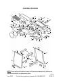
1
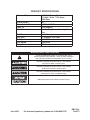
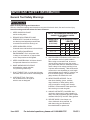
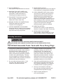
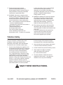
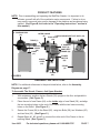
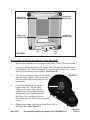
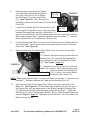
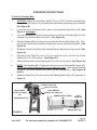
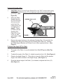
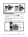
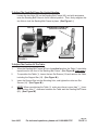
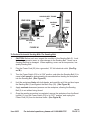
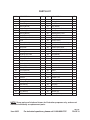
PRODUCT SPECIFICATIONS
Electrical Requirements
Overall Height
Table Surface Dimensions
Table Tilt
Work Table Options
Belt Size
Disc Size
Belt Speed
Disk Speed
Weight
1 HP, Ball Bearing Motor
110 Volt / 60 Hz / 12.8 Amps
3450 Rpm
40"
6-1/2" x 12-3/4"
0-50 Degrees
For Sanding Disc or Sanding Belt
Use
6" x 48"
9" Diameter, PSA Type
1400 FPM
1800 RPM
121 lb.
WARNING SYMBOLS AND DEFINITIONS
This is the safety alert symbol. It is used to alert you to
potential personal injury hazards. Obey all safety messages
that follow this symbol to avoid possible injury or death.
Indicates a hazardous situation which, if not avoided,
will result in death or serious injury.
Indicates a hazardous situation which, if not avoided,
could result in death or serious injury.
Indicates a hazardous situation which, if not avoided,
could result in minor or moderate injury.
Addresses practices not related to personal injury.
Item 6852
For technical questions, please call 1-888-866-5797.
REV 07g
PAGE 2
IMPORTANT SAFETY INFORMATION
General Tool Safety Warnings
Read all safety warnings and instructions.
Failure to follow the warnings and instructions may result in electric shock, fire and/or serious injury.
Save all warnings and instructions for future reference.
1. KEEP GUARDS IN PLACE
and in working order.
2. REMOVE ADJUSTING KEYS AND
WRENCHES. Form habit of checking to
see that keys and adjusting wrenches are
removed from tool before turning it on.
3. KEEP WORK AREA CLEAN.
Cluttered areas and benches invite accidents.
4. DON’T USE IN DANGEROUS
ENVIRONMENT. Don’t use power tools
in damp or wet locations, or expose them
to rain. Keep work area well lighted.
5. KEEP CHILDREN AWAY. All visitors should
be kept safe distance from work area.
6. MAKE WORKSHOP KID PROOF
with padlocks, master switches,
or by removing starter keys.
7. DON’T FORCE TOOL. It will do the job better
and safer at the rate for which it was designed.
8. USE RIGHT TOOL. Don’t force
tool or attachment to do a job for
which it was not designed.
Table A: RECOMMENDED MINIMUM WIRE
GAUGE FOR EXTENSION CORDS
(120 VOLT)
NAMEPLATE
AMPERES
(at full load)
EXTENSION CORD
LENGTH
25′ 50′ 100′ 150′
0–6
18
16
16
14
6.1 – 10
18
16
14
12
10.1 – 12
16
16
14
12
12.1 – 16
14
12
Do not use.
9. USE PROPER EXTENSION CORD. Make sure
your extension cord is in good condition.
When using an extension cord, be sure to
use one heavy enough to carry the current
your product will draw. An undersized cord will
cause a drop in line voltage resulting in loss
of power and overheating. Table A shows the
correct size to use depending on cord length
and nameplate ampere rating. If in doubt, use
the next heavier gauge. The smaller the
gauge number, the heavier the cord.
10. WEAR PROPER APPAREL. Do not
wear loose clothing, gloves, neckties,
rings, bracelets, or other jewelry which
may get caught in moving parts. Nonslip
footwear is recommended. Wear protective
hair covering to contain long hair.
11. ALWAYS USE SAFETY GLASSES. Also
use face or dust mask if cutting operation is
dusty. Everyday eyeglasses only have impact
resistant lenses, they are NOT safety glasses.
12. SECURE WORK. Use clamps or a
vise to hold work when practical. It’s
safer than using your hand and it
frees both hands to operate tool.
Item 6852
For technical questions, please call 1-888-866-5797.
PAGE 3
13. DON’T OVERREACH.
Keep proper footing and balance at all times.
14. MAINTAIN TOOLS WITH CARE. Keep
tools sharp and clean for best and safest
performance. Follow instructions for
lubricating and changing accessories.
15. DISCONNECT TOOLS before servicing;
when changing accessories, such as
blades, bits, cutters, and the like.
16. REDUCE THE RISK OF UNINTENTIONAL
STARTING. Make sure switch is in
off position before plugging in.
17. USE RECOMMENDED ACCESSORIES.
Consult the owner’s manual for recommended
accessories. The use of improper accessories
may cause risk of injury to persons.
18. NEVER STAND ON TOOL.
Serious injury could occur if the tool is tipped or
if the cutting tool is unintentionally contacted.
19. CHECK DAMAGED PARTS. Before further
use of the tool, a guard or other part that is
damaged should be carefully checked to
determine that it will operate properly and
perform its intended function – check for
alignment of moving parts, binding of moving
parts, breakage of parts, mounting, and any
other conditions that may affect its operation.
A guard or other part that is damaged
should be properly repaired or replaced.
20. DIRECTION OF FEED.
Feed work into a blade or cutter against the
direction of rotation of the blade or cutter only.
21. NEVER LEAVE TOOL RUNNING
UNATTENDED. TURN POWER OFF. Don’t
leave tool until it comes to a complete stop.
Grounding Instructions
TO PREVENT ELECTRIC SHOCK AND DEATH FROM INCORRECT
GROUNDING WIRE CONNECTION READ AND FOLLOW THESE INSTRUCTIONS:
110-120 VAC Grounded Tools: Tools with Three Prong Plugs
1. In the event of a malfunction or breakdown,
grounding provides a path of least resistance
for electric current to reduce the risk of
electric shock. This tool is equipped with an
electric cord having an equipment-grounding
conductor and a grounding plug. The plug
must be plugged into a matching outlet that is
properly installed and grounded in accordance
with all local codes and ordinances.
3. Improper connection of the equipmentgrounding conductor can result in a risk
of electric shock. The conductor with
insulation having an outer surface that is
green with or without yellow stripes is the
equipment-grounding conductor. If repair or
replacement of the electric cord or plug is
necessary, do not connect the equipmentgrounding conductor to a live terminal.
2. Do not modify the plug provided – if it will
not fit the outlet, have the proper outlet
installed by a qualified electrician.
4. Check with a qualified electrician or service
personnel if the grounding instructions are
not completely understood, or if in doubt as
to whether the tool is properly grounded.
5. Use only 3-wire extension cords that
have 3-prong grounding plugs and 3-pole
receptacles that accept the tool’s plug.
6. Repair or replace damaged or
worn cord immediately.
Item 6852
For technical questions, please call 1-888-866-5797.
PAGE 4
Grounding
Pin
125 VAC 3-Prong Plug and Outlet
(for up to 125 VAC and up to 15 A)
7. This tool is intended for use on a circuit that
has an outlet that looks like the one illustrated
above in “125 VAC 3-Prong Plug and Outlet”.
The tool has a grounding plug that
looks like the plug illustrated above in
“125 VAC 3-Prong Plug and Outlet”.
8. The outlet must be properly installed
and grounded in accordance with
all codes and ordinances.
9. Do not use an adapter to connect
this tool to a different outlet.
Sander Tool Safety Warnings
For Your Own Safety Read Instruction
Manual Before Operating Tool Sander
1. Wear eye protection.
2. Support workpiece with miter
gauge, backstop, or worktable.
3. Maintain 1/16 inch maximum clearance
between table and sanding belt or disc.
4. Avoid kickback by sanding in accordance
with the directional arrows.
5. The backstop is a fence near the surface
that helps the operator maintain control
of the workpiece and prevents the
workpiece from being pulled into the
machine. For safety, it must be adjusted
very close to the sanding surface.
6. The worktable is the surface mounted
close to the sanding surface that the
operator rests the workpiece against to
prevent it from being pulled by the sanding
surface. For safety, it must be adjusted
very close to the sanding surface.
7. The sanding belt is designed to rotate down
towards the table while the disc rotates
both up from the table and down towards
the table. Sand only on the downward moving
surface of the disc - sanding on the upward
moving surface may result in the workpiece
being thrown up and towards the operator.
8. DO NOT OPERATE WITH ANY
GUARD DISABLED, DAMAGED, OR
REMOVED. Moving guards must
move freely and close instantly.
Item 6852
9. The use of accessories or attachments
not recommended by the manufacturer
may result in a risk of injury to persons.
10. When servicing use only identical
replacement parts.
11. Do not depress the spindle lock when
starting or during operation.
12. Only use safety equipment that has been
approved by an appropriate standards
agency. Unapproved safety equipment
may not provide adequate protection. Eye
protection must be ANSI-approved and
breathing protection must be NIOSH-approved
for the specific hazards in the work area.
13. Stay alert, watch what you are doing and
use common sense when operating a
power tool. Do not use a power tool while
you are tired or under the influence of
drugs, alcohol or medication. A moment
of inattention while operating power tools
may result in serious personal injury.
14. Industrial applications must
follow OSHA guidelines.
15. Maintain labels and nameplates on the tool.
These carry important safety information.
If unreadable or missing, contact
Harbor Freight Tools for a replacement.
16. Avoid unintentional starting.
Prepare to begin work before
turning on the tool.
For technical questions, please call 1-888-866-5797.
PAGE 5
17. People with pacemakers should
consult their physician(s) before use.
Electromagnetic fields in close proximity to
heart pacemaker could cause pacemaker
interference or pacemaker failure.
18. WARNING: Some dust created by power
sanding, sawing, grinding, drilling, and other
construction activities, contains chemicals
known [to the State of California] to cause
cancer, birth defects or other reproductive
harm. Some examples of these chemicals are:
• Lead from lead-based paints
• Crystalline silica from bricks and cement or
other masonry products
• Arsenic and chromium from
chemically treated lumber
Your risk from these exposures
varies, depending on how often you
do this type of work. To reduce your exposure
to these chemicals: work in a well ventilated
area, and work with approved safety
equipment, such as those dust masks that
are specially designed to filter out microscopic
particles. (California Health & Safety
Code § 25249.5, et seq.)
19. WARNING: Handling the cord on this product
will expose you to lead, a chemical known
to the State of California to cause cancer,
and birth defects or other reproductive harm.
Wash hands after handling. (California
Health & Safety Code § 25249.5, et seq.)
20. The warnings, precautions, and instructions
discussed in this instruction manual cannot
cover all possible conditions and situations that
may occur.
It must be understood by the operator that
common sense and caution are factors
which cannot be built into this product,
but must be supplied by the operator.
Vibration Safety
This tool vibrates during use. Repeated or
long-term exposure to vibration may cause
temporary or permanent physical injury,
particularly to the hands, arms and shoulders.
To reduce the risk of vibration-related injury:
1. Anyone using vibrating tools regularly or for
an extended period should first be examined
by a doctor and then have regular medical
check-ups to ensure medical problems
are not being caused or worsened from
use. Pregnant women or people who have
impaired blood circulation to the hand, past
hand injuries, nervous system disorders,
diabetes, or Raynaud’s Disease should not use
this tool. If you feel any medical or physical
symptoms related to vibration (such as
tingling, numbness, and white or blue fingers),
seek medical advice as soon as possible.
2. Do not smoke during use. Nicotine reduces
the blood supply to the hands and fingers,
increasing the risk of vibration-related injury.
3. Use tools with the lowest vibration when there
is a choice between different processes.
4. Include vibration-free periods each day of work.
5. Grip workpiece as lightly as possible
(while still keeping safe control of
it). Let the tool do the work.
6. To reduce vibration, maintain the tool as
explained in this manual. If any abnormal
vibration occurs, stop use immediately.
SAVE THESE INSTRUCTIONS.
Item 6852
For technical questions, please call 1-888-866-5797.
PAGE 6
PRODUCT FEATURES
NOTE: Prior to assembling and operating the Belt/Disc Sander, it is important to familiarize yourself with all of the machine’s major components. Failure to do so
may result in personal injury and/or damage to the machine and workpiece being
sanded. (See Figure B, and refer to the “Operating Instructions” section in
this manual.)
9” SANDING DISC
(15)
MITER GAUGE
(3)
LOCK KNOB/ADJUST NUT ASSY. (44)
BACK STOP
(39)
TABLE (1)
6” SANDING
BELT (2)
PULLEY
COVER
(22)
BASE
(51)
SAND BELT
FRAME (40)
POWER
SWITCH
(53)
POWER
CORD
(55)
FIGURE B
STAND
(56
FRAME
(64)
ASSEMBLY INSTRUCTIONS
NOTE: For additional references to the parts listed below, refer to the Assembly
Diagram on page 17.
To Assemble The Stands, Frames, And Upper Bracket:
1.
With assistance,positionthetwoStands(56)uprightonthefloorandparallelto
one another. (See Figure C.)
2.
Place the end of one Frame (64) on the inside edge of one Stand (56), and align
the two mounting holes on the end of the Frame with the two lower mounting
holes on the Stand. (See Figure C.)
3.
Secure the Frame (64) to the Stand (56), using two Bolts (58), two Washers (60),
and two Nuts (63). (See Figure C.)
4.
Repeat Steps #1, #2, and #3 to connect the other end of the Frame to the remaining Stand. (See Figure C.)
Item 6852
For technical questions, please call 1-888-866-5797.
PAGE 7
5.
To connect the remaining Frame (64) to the two Stands (56), follow Steps #1, #2,
#3, and #4). (See Figure C.)
UPPER BRACKET (57)
BOLT (58)
WASHER (60)
NUT (63)
STAND
(56)
FRAME
(64)
UPPER
BRACKET
(57)
(mostly hidden)
STAND
(56)
BOLT (58)
WASHER (60)
NUT (63)
FRAME
(64)
FIGURE C
6.
Place both Upper Brackets (57) on the top edges of the two Stands (56), and
align the eight mounting holes (two on each end) of the Brackets with the eight
mounting holes (two on each end) of the Stands. (See Figure C.)
7.
Secure both Upper Brackets (57) to the two Stands (56), using eight Bolts (58),
Washers (60), and Nuts (63). (See Figure C.)
8.
With assistance, carefully tip the assembled Stand on its side. Attach a Rubber
Foot (59) to each of the Stand’s four corners, using four Rubber Feet, four Washers (60), and four Screws (61). Then, place the Stand back in its upright position.
(See Figure D.)
To Attach The Base To The Upper Bracket:
1.
With assistance, place the Base (51) of the Belt/Disc Sander on top of the Upper
Brackets (57). Align the four threaded mounting holes on the Base with the four
mounting holes on the Upper Brackets. (See Figures B, and D.)
2.
From underneath the Stand, secure the Base (51) to the Upper Brackets (57) by
inserting four Screws (66), with four Washers (65), upward through the Stand’s
fourmountingholes.Then,firmlytightenthefourScrewsintothefourthreaded
mounting holes on the Base. (See Figure D.)
Item 6852
For technical questions, please call 1-888-866-5797.
REV 05b
PAGE 8
SCREW (66)
WASHER (65)
SCREW (66)
WASHER (65)
SCREW (66)
WASHER (65)
SCREW (66)
WASHER (65)
FIGURE D
SCREW
(61)
WASHER
(60)
RUBBER
FOOT
(59)
Figure A:
To Assemble the Pulleys, Sanding Disc Plate, and Table:
1.
Remove the 4 screws from the cover on the Pulley Cover (22) and set aside.
2.
Line up the three bolt holes on the Pulley Cover (22) with the threaded holes
in the Bracket (26). Place a Washer (21) over each of 3 Screws (20). Insert a
Screw (20) into each hole and tighten. (See Figure E.)
3.
This item is packed with tape on the shafts to
keep the keys in place. Remove the tape
from the upper shaft, being careful to not
lose the key.
4.
Screw (20)
Loosen the Set Screw (14) on the
Large Pulley (19). Put the Large
Pulley on the upper shaft, with the
smaller step on the pulley inside and
with the key lined up with the slot on
the Pulley. Be sure the key stays in
the correct position, all the way through the
pulley.
5.
Repeat steps 3 and 4 putting the Small Pulley (52) on
the lower shaft. (See Figure F.)
Item 6852
For technical questions, please call 1-888-866-5797.
FIGURE E
REV04h;05b
PAGE 9
6.
7.
Carefully align both pulleys and tighten.
Large PulFIGURE F
Useaflatheadscrewdriverthroughthe
ley
(19)
slot in the Pulley Cover (22) to tighten
the Set Screw (14) on the Large Pulley
(19). (See Figure G.) Use a hex key (not
included) to tighten the Set Screw (14) on the Small
Pulley (52).
Small PulLoosen the 4 Screws (48) that hold the Motor (30)
ley (52)
just enough to let the Motor move. Move the Motor
towards the Large Pulley enough to let the Belt (17)
slip on over both Pulleys. Move the Motor away from the Large Pulley until the
Belt is tight enough so that, if pushed, it doesn’t move more than 1/2”. Hold the
Motor in place while you retighten the 4 Screws (48).
8.
PuttheSandingDiscPlate(16)ontheendoftheshaftsothatit’sflushwiththe
end of the shaft. Tighten its set screw, once again using the slot in the Pulley
Cover (22). (See Figure G.)
9.
Check to make sure the Sanding Disc Plate (16) is free of dirt, oil, and other
debris.
FIGURE G
10. Remove the paper backing on the adhesive
Sanding Disc (15), and stick the Sanding Disc
firmlyandevenlyontotheSandingDiscPlate
(16). (See Figure I, page 11.)
11. Replace cover of the Pulley Cover (22) and
tighten the 4 screws. Verify that the pulley cover
does not contact the Sanding Disc
Hole for Support Bar (18) (15). If it does, you need to adjust
the Sanding Disc Plate (16).
NOTE: When positioning the Table (1), make sure there is more than 1/16” clearance but
less than 1/8” clearance between the Table and the Sanding Disc (15).
12.
Insert the round end of the Support Bar (18) into the hole on the side of the
Base (18). (See Figure G.) Put the Table Support Bracket (9) over the end of
the Support Bar, with the tapered side of the Bracket facing the Sanding Disc
(15)andalsotheflatsideoftheBarlinedupwiththeSetScrew.Tightenthe
Set Screw (14) on the Table Support Bracket. Set the Table Support Bracket as
shown in Figure J, page 12. Tighten the two Set Screws (14) on the side of the
Base to secure the bar.
Item 6852
For technical questions, please call 1-888-866-5797.
REV 04b
PAGE 10
OPERATING INSTRUCTIONS
To Install A Sanding Belt:
1.
CAUTION: Always turn the Power Switch (53) to its “OFF” position and unplug the
Power Cord (55) from its 110 volt electrical outlet before performing this procedure.
(See Figure B.)
2.
Loosen the two Lock Knobs (44) in order to unlock the two Adjust Nuts (44). (See
Figure H, next page.)
3.
Turn the two Adjust Nuts (44) counterclockwise to allow the Sanding Belt (2) to be
inserted onto the Sand Belt Frame (40). (See Figure H.)
4.
Slide the Sanding Belt (2) fully and evenly onto the Sanding Belt Frame (40). Then,
turn the two Adjust Nuts clockwise to tighten the tension on the Sanding Belt. (See
Figure H.)
5.
Retighten the two Lock Knobs (44), and lock the two Adjust Nuts (44) in place. (See
Figure H.)
6.
Plug the Power Cord (55) into a 110 volt electrical outlet, and turn the Power
Switch (53) to its “ON” position. (See Figure B.)
7.
AllowsufficienttimefortheSandingBelt(2)toturnatfullspeed.(See Figure H.)
8.
NOTE: If the Sanding Belt (2) appears to be too loose on the Sand Belt Frame (40),
turn off the machine and unplug it from its electrical outlet. Then repeat Steps #2
through #7 to further increase the tension on the Sanding Belt. (See Figures B
and H.)
9.
Attach the Back Stop (39) to the side of the Sanding Belt Frame (40), as shown in
Figure H.
BACK STOP (39)
Sand in this area.
LOCK KNOB &
ADJUST NUT ASSY.
(44)
SANDING BELT (2)
FIGURE H
Item 6852
LOCK KNOB &
ADJUST NUT ASSY (44)
SANDING BELT FRAME
(40)
LOCK
KNOB (44)
ADJUST NUT (44)
For technical questions, please call 1-888-866-5797.
REV 04b
PAGE 11
To Install A Sanding Disc:
1.
CAUTION: Always turn the Power Switch (53) to its “OFF” position and unplug
the Power Cord (55) from its 110 volt electrical outlet before performing this
procedure. (See
SANDING DISC
Figure B.)
(15)
2.
Swing the Table
Support Bracket
(9) out of the way
and remove the
cover from the
Pulley Cover ( 22)
as explained on
page 9. Check
to make sure the
Sanding Disc
Plate (16) is free
of dirt, oil, and
other debris. (See
Figure I.)
3.
SANDING DISC PLATE
(16)
FIGURE I
Remove the paper backing on the adhesive Sanding Disc (15), and stick the
SandingDiscfirmlyandevenlyontotheSandingDiscPlate(16).Restore
the Table Support Bracket and Pulley Cover to their original positions. (See
Figure I.)
To Adjust The Angle Of The Table:
1.
The angle of the Table (1) may be adjusted from 0 to 45 Degrees. (See Figure J.)
2.
To adjust the angle of the Table (1), slightly loosen the Knob (10). (See Figure J.)
3.
Observe the Angle Gauge (5). Then raise or lower the Table until the desired
angle of the Table is shown on the Angle Gauge. (See Figure J.)
4.
Once the desired angle of the Table (1) is obtained, retighten the Knob (10).
(See Figure J.)
Item 6852
For technical questions, please call 1-888-866-5797.
REV 04b
PAGE 12
TABLE (1)
TABLE (1)
ANGLE
GAUGE
(5)
KNOB
(10)
ANGLE
GAUGE
(5)
FIGURE J
KNOB
(10)
To Adjust The Angle Of The Miter Gauge:
1.
The angle of the Miter Gauge (3) may be adjusted to the right 0 to 45 Degrees
and to the left 0 to 45 Degrees. (See Figure K, next page.)
2.
To adjust the angle of the Miter Gauge (3), slightly loosen the Miter Gauge Knob.
(See Figure K.)
3.
Observe the Angle Scale on the Miter Gauge (3). Then move the Miter Gauge
Body to the right or left until the desired angle of the Miter Gauge is shown on the
Angle Scale. (See Figure K.)
4.
Once the desired angle of the Miter Gauge (3) is obtained, retighten the Miter
Gauge Knob. (See Figure K.)
MITER GAUGE
(3)
MITER GAUGE KNOB
ANGLE SCALE
FIGURE K
Item 6852
For technical questions, please call 1-888-866-5797.
REV 04b
PAGE 13
To Adjust The Sand Belt Frame For Vertical Sanding:
Loosen the two Nuts (36) on the Sanding Belt Frame (40), and with assistance
raise the Sanding Belt Frame to its full verticalposition.Then,firmlyretightenthe
two Nuts to lock the Sanding Belt Frame in place. (See Figure L.)
NUT (36)
SANDING BELT FRAME (40)
(VERTICAL POSITION)
FIGURE L
To Adjust The Position Of The Table:
1.
When the Sanding Belt Frame (40) is in its vertical position, the Table (1) should be
repositioned to the front of the Sanding Belt Frame. (See Figure M, next page.)
2.
To reposition the Table (1), loosen the two Set Screws (14) and remove the Table,
including the Support Bar (18). (See Figure M.)
3.
Insert the Support Bar into the Mounting Hole, and tighten the other two Set
Screws (14). (See Figure M.)
4.
NOTE: When repositioning the Table (1), make sure there is more than 1/16” clearance but less than 1/8” clearance between the Table and the Sanding Belt Frame
(40). (See Figure M.)
Item 6852
For technical questions, please call 1-888-866-5797.
REV 04b
PAGE 14
END VIEW
SANDING BELT FRAME
(40)
TABLE (1)
SANDING
BELT
(2)
SUPPORT BAR
(18)
SET SCREW
(14)
FIGURE M
SIDE
VIEW
TABLE
(1)
SUPPORT
BAR
(18)
SET SCREW
(14)
To Perform Horizontal Sanding With The Sanding Belt:
1.
CAUTION: Before each use, inspect the condition of the Sanding Belt (2). Look
for tearing, excessive wear, or other damage to the Sanding Belt. Never use a
Sanding Belt that is damaged. When replacing, never use an inexpensive, low
quality Sanding Belt.
2.
Plug the Power Cord (55) into a grounded, 110 Volt electrical outlet. (See Figure B.)
3.
Turn the Power Switch (53) to its “ON” position, and allow the Sanding Belt (2) to
come to full speed for approximately ten seconds before feeding the workpiece
into the Sanding Belt. (See Figure B.)
4.
Hold the workpiece firmlywithbothhands,andcarefullysetitflatandlevelupon
the Sanding Belt (2) and against the Back Stop (39). (See Figure B.)
5.
Apply moderate downward pressure on the workpiece, allowing the Sanding
Belt (2) to cut without being forced.
6.
Once the sanding procedure is completed, remove the workpiece from the Sanding Belt (2), turn the Power Switch (53) to its “OFF” position, and unplug the
Power Cord (55) from its electrical outlet. (See Figure B.)
Item 6852
For technical questions, please call 1-888-866-5797.
REV 04b
PAGE 15
To Perform Horizontal Sanding With The Sanding Disc:
1.
CAUTION: Before each use, inspect the condition of the Sanding Disc (15).
Look for tearing, excessive wear, or other damage to the Sanding Disc. Never
use a Sanding Disc that is damaged. When replacing, never use an inexpensive,
low quality Sanding Disc.
2.
NOTE: The Sanding Disc (15) is typically used for smaller workpieces.
3.
Plug the Power Cord (55) into a grounded, 110 Volt electrical outlet. (See Figure B.)
4.
Turn the Power Switch (53) to its “ON” position, and allow the Sanding Disc (15)
to come to full speed for approximately ten seconds before feeding the workpiece into the Sanding Disc. (See Figure B.)
5.
Hold the workpiece firmlywithbothhands,andcarefullysetitflatandlevelupon
the Table (1). (See Figure B.)
6.
Apply moderate inward pressure on the workpiece, allowing the Sanding
Disc (15) to cut without being forced.
7.
Once the sanding procedure is completed, remove the workpiece from the Sanding Disc (15), turn the Power Switch (53) to its “OFF” position, and unplug the
Power Cord (55) from its electrical outlet. (See Figure B.)
To Perform Vertical Sanding With The Sanding Belt:
1.
Adjust the Sand Belt Frame (40) and Table (1) for a vertical sanding procedure.
(See Figures L, and M.)
2.
Plug the Power Cord (55) into a grounded, 110 Volt electrical outlet. (See Figure B.)
3.
Turn the Power Switch (53) to its “ON” position, and allow the Sanding Belt (2) to
come to full speed for approximately ten seconds before feeding the workpiece
into the Sanding Belt. (See Figure M.)
4.
Hold the workpiece firmlywithbothhands,andcarefullysetitflatandlevelupon
the Table (1). (See Figure M.)
5.
Apply moderate inward pressure on the workpiece, allowing the Sanding Belt (2)
to cut without being forced. (See Figure M.)
6.
Once the sanding procedure is completed, remove the workpiece from the Sanding Belt (2), turn the Power Switch (53) to its “OFF” position, and unplug the
Power Cord (55) from its electrical outlet. (See Figure B.)
Item 6852
For technical questions, please call 1-888-866-5797.
REV 04b
PAGE 16
INSPECTION, MAINTENANCE, AND CLEANING
1.
CAUTION: Always turn the Power Switch (53) to its “OFF” position and unplug the Power Cord (55) from its 110 volt electrical outlet before performing any inspection, adjustments, maintenance, or cleaning.
2.
BEFORE EACH USE, inspect the general condition of the Belt/Disc Sander.
Check for loose screws, misalignment or binding of moving parts, cracked or
broken parts, damaged electrical wiring, excessively loose Sanding Belt (2) and
Sanding Disc (15), and any other condition that may affect its safe operation. If
abnormal noise or vibration occurs, have the problem corrected before further
use. Do not use damaged equipment.
3.
DAILY: Sanding Belts (2) and Sanding Discs (15) must be sharp and clean to
perform properly. Depending on materials sanded and frequency of tool use,
Sanding Belts and Sanding Discs become clogged with wood particles and dull.
Dull Sanding Belts and Sanding Discs rub the workpiece rather than cut, which
results in increased friction, higher temperatures, and a burned workpiece. As
often as possible, check the condition of the Sanding Belt and Sanding Disc and,
if necessary, replace a worn Sanding Belt and Sanding Disc with a new, 6” wide
by 48” Sanding Belt and 9” diameter Sanding Disc.
4.
DAILY: With a soft brush, cloth, or vacuum, remove all sawdust and debris from
the Belt/Disc Sander. Then, use a premium quality, lightweight machine oil to
lubricate all moving parts.
PLEASE READ THE FOLLOWING CAREFULLY
THE MANUFACTURER AND/OR DISTRIBUTOR HAS PROVIDED THE PARTS LIST AND
ASSEMBLY DIAGRAM IN THIS MANUAL AS A REFERENCE TOOL ONLY. NEITHER THE
MANUFACTURER OR DISTRIBUTOR MAKES ANY REPRESENTATION OR WARRANTY OF
ANY KIND TO THE BUYER THAT HE OR SHE IS QUALIFIED TO MAKE ANY REPAIRS TO
THE PRODUCT, OR THAT HE OR SHE IS QUALIFIED TO REPLACE ANY PARTS OF THE
PRODUCT. IN FACT, THE MANUFACTURER AND/OR DISTRIBUTOR EXPRESSLY STATES
THAT ALL REPAIRS AND PARTS REPLACEMENTS SHOULD BE UNDERTAKEN BY CERTIFIED AND LICENSED TECHNICIANS, AND NOT BY THE BUYER. THE BUYER ASSUMES ALL
RISK AND LIABILITY ARISING OUT OF HIS OR HER REPAIRS TO THE ORIGINAL PRODUCT
OR REPLACEMENT PARTS THERETO, OR ARISING OUT OF HIS OR HER INSTALLATION
OF REPLACEMENT PARTS THERETO.
Item 6852
For technical questions, please call 1-888-866-5797.
PAGE 17
PARTS LIST
PART # DESCRIPTION
QTY PART # DESCRIPTION
QTY
1
Table
1
34
Set Screw
2
2
Sanding Belt
1
35
Driving Roller
1
3
Miter Gauge
1
36
Nut (M8)
6
4
Screw (M5x30)
2
37
Key (B5x50)
1
5
Angle Gauge
1
38
Driving Roller Shaft
1
6
Washer (8)
6
39
Back Stop
1
7
Screw (M8x12)
1
40
Sanding Belt Frame
1
8
Nut (M5)
2
41
Roller Adjust Bar
2
9
Table Support Bracket
1
42
Spring Pin (5)
2
10
Knob
1
43
Leader Roller
1
11
Screw (M5x10)
1
44
Lock Knob/Adjust Nut Assy
2
12
Pointer
1
45
Spring
2
13
Set Screw
1
46
Leader Roller Shaft
1
14
Set Screw
7
47
Support Bolt (M16x240)
1
15
Sanding Disc
1
48
Screw (M8x30)
4
16
Sanding Disc Plate
1
49
Nut (M8x30)
1
17
V-Belt (A-710)
1
50
Cord Clamp
1
18
Support Bar
1
51
Base
1
19
Large Pulley
1
52
Small Pulley
1
20
Screw (M8x10)
3
53
Switch
1
21
Washer (8)
6
54
Cord Clamp
1
22
Pulley Cover
1
55
Power Cord
1
23
Screw (M8x35)
2
56
Stand
2
24
Washer (4)
1
57
Upper Bracket
2
25
Knob
1
58
Bolt (M8x10)
16
26
Bracket
1
59
Rubber Foot
4
27
Retaining Ring
4
60
Washer (8)
8
28
C-Snap Ring
1
61
Screw (M5x12)
8
29
Ball Bearing
4
62
Nut (M5)
4
30
Motor
1
63
Nut (M8)
4
31
Screw (M8x25)
5
64
Frame
2
32
Key (B5x20)
1
65
Washer (8)
4
33
Tube
2
66
Screw (M8x10)
4
NOTE: Some parts are listed and shown for illustration purposes only, and are not
available individually as replacement parts.
Item 6852
For technical questions, please call 1-888-866-5797.
REV 05b
PAGE 18
ASSEMBLY DIAGRAM
2
1
6
7
5
10
11
35 33
34
6
12
13
3
9
14
8
4
18
19
20
21
22
23 6
26
29
28
27
3121
16
32
52
17
36
29
27
6
40 31
30
48
6
14
45
45
44
47 29
50
51
53
44
41
42
27
6
36
39
41 42
49
14
15
14
21
38
37
54
43
27
29
46
55
56
56
65
57
58
65
66
64
59
60
61
58
66
58
63
63
64
62
60
58
59
60
61
NOTE: Some parts are listed and shown for illustration purposes only, and are not
available individually as replacement parts.
Item 6852
For technical questions, please call 1-888-866-5797.
REV 05b
PAGE 19
Limited 90 Day Warranty
Harbor Freight Tools Co. makes every effort to assure that its products meet high quality and durability
standards, and warrants to the original purchaser that this product is free from defects in materials
and workmanship for the period of 90 days from the date of purchase. This warranty does not apply to
damage due directly or indirectly, to misuse, abuse, negligence or accidents, repairs or alterations outside
our facilities, criminal activity, improper installation, normal wear and tear, or to lack of maintenance.
We shall in no event be liable for death, injuries to persons or property, or for incidental, contingent,
special or consequential damages arising from the use of our product. Some states do not allow the
exclusion or limitation of incidental or consequential damages, so the above limitation of exclusion
may not apply to you. THIS WARRANTY IS EXPRESSLY IN LIEU OF ALL OTHER WARRANTIES,
EXPRESS OR IMPLIED, INCLUDING THE WARRANTIES OF MERCHANTABILITY AND FITNESS.
To take advantage of this warranty, the product or part must be returned to us with transportation charges
prepaid. Proof of purchase date and an explanation of the complaint must accompany the merchandise.
If our inspection verifies the defect, we will either repair or replace the product at our election or we may
elect to refund the purchase price if we cannot readily and quickly provide you with a replacement. We will
return repaired products at our expense, but if we determine there is no defect, or that the defect resulted
from causes not within the scope of our warranty, then you must bear the cost of returning the product.
This warranty gives you specific legal rights and you may also
have other rights which vary from state to state.
3491 Mission Oaks Blvd. • PO Box 6009 • Camarillo, CA 93011 • 1-888-866-5797
Item 6852
For technical questions, please call 1-888-866-5797.
PAGE 20