1
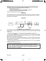
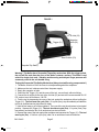
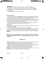
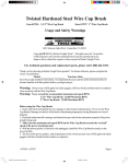
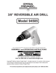
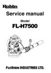
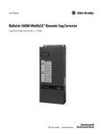
18 GUAGE, 5/8”-2”
AIR BRAD NAILER
Model 54461
ASSEMBLY and OPERATING
INSTRUCTIONS
®
3491 Mission Oaks Blvd., Camarillo, CA 93011
Visit our Web site at http://www.harborfreight.com
Copyright c 2003 by Harbor Freight Tools® . All rights reserved. No portion of this
manual or any artwork contained herein may be reproduced in any shape or form
without the express written consent of Harbor Freight Tools.
For technical questions and replacement parts, please call 1-800-444-3353
54461.p65
1
10/10/03, 2:29 PM
Specifications
Air Inlet
Recommended Air Pressure
Maximum Air Pressure
Nail Type
Safety Feature
Magazine Capacity
Air Consumption
Overall Dimensions
1/4”- 18 NPT
60-115 PSI
130 PSI
5/8” to 2” 18 Gauge Brads
Sequential Trip Safety Trigger
110 - Side Loading Magazine
4 CFM @ 90 PSI
10” x 9-3/8” x 2-1/4”
Save This Manual
You will need the manual for the safety warnings and precautions, assembly instructions,
operating and maintenance procedures, parts list and diagram. Keep your invoice with this
manual. Write the invoice number on the inside of the front cover. Keep the manual and
invoice in a safe and dry place for future reference.
Safety Warnings and Precautions
WARNING: When using tool, basic safety precautions should always be followed to
reduce the risk of personal injury and damage to equipment.
Read all instructions before using this tool!
1.
Keep work area clean. Cluttered areas invite injuries.
2.
Observe work area conditions. Do not use machines or power tools in damp or wet
locations. Don’t expose to rain. Keep work area well lighted. Do not use electrically
powered tools in the presence of flammable gases or liquids.
3.
Keep children away. Children must never be allowed in the work area. Do not let
them handle machines, tools, extension cords, or air hoses.
4.
Store idle equipment. When not in use, tools must be stored in a dry location to
inhibit rust. Always lock up tools and keep out of reach of children.
5.
Use the right tool for the job. Do not attempt to force a small tool or
attachment to do the work of a larger industrial tool. There are certain applications for
which this tool was designed. It will do the job better and more safely at the rate for
which it was intended. Do not modify this tool and do not use this tool for a purpose for
which it was not intended.
6.
Dress properly. Do not wear loose clothing or jewelry as they can be caught in
moving parts. Protective, electrically non-conductive clothes and non-skid footwear
are recommended when working. Wear restrictive hair covering to contain long hair.
7.
Use eye and ear protection. Always wear ANSI approved impact safety goggles.
8.
Do not overreach. Keep proper footing and balance at all times. Do not reach over
or across running machines or air hoses.
Page 2
SKU 54461
54461.p65
2
10/10/03, 2:29 PM
9.
Maintain tools with care. Keep tools clean for better and safer performance. Follow
instructions for lubricating and changing accessories. Inspect tool cords and air hoses
periodically and, if damaged, have them repaired by an authorized technician. The
handles must be kept clean, dry, and free from oil and grease at all times.
10. Disconnect air supply. Disconnect air hose when not in use.
11. Remove adjusting keys and wrenches. Check that keys and adjusting wrenches
are removed from the tool or machine work surface before plugging it in.
12. Avoid unintentional starting. Be sure your finger is off the trigger when not in use
and before plugging in. Do not carry any tool with your finger on the trigger, whether it
is plugged in or not.
13. Stay alert. Watch what you are doing, use common sense. Do not operate any tool
when you are tired.
14. Check for damaged parts. Before using any tool, any part that appears damaged
should be carefully checked to determine that it will operate properly and perform its
intended function. Check for alignment and binding of moving parts; any broken parts
or mounting fixtures; and any other condition that may affect proper operation. Any
part that is damaged should be properly repaired or replaced by a qualified technician.
Do not use the tool if the trigger does function properly.
15. Guard against electric shock. Prevent body contact with grounded surfaces such as
pipes, radiators, ranges, and refrigerator enclosures.
16. Replacement parts and accessories. When servicing, use only identical
replacement parts. Use of any other parts will void the warranty.
17. Do not operate tool if under the influence of alcohol or drugs. Read warning
labels if taking prescription medicine to determine if your judgement or reflexes are
impaired while taking drugs. If there is any doubt, do not operate the Nailer.
18. Use proper size and type extension cord. If an extension cord is required, it must
be of the proper size and type to supply the correct current to the tool without heating
up. Otherwise, the extension cord could melt and catch fire, or cause electrical
damage to the tool. Check your air compressor’s manual for the appropriate size cord.
19. Maintenance. For your safety, maintenance should be performed regularly by a
qualified technician.
20. Compressed air only. Never use combustible gases as a power source.
Note: Performance of the air compressor (if powered by line voltage) may vary depending on variations in local line voltage. Extension cord usage may also affect tool performance.
Warning: The warnings, cautions, and instructions discussed in this instruction manual
cannot cover all possible conditions and situations that may occur. It must be understood by the operator that common sense and caution are factors which cannot be
built into this product, but must be supplied by the operator.
Page 3
SKU 54461
54461.p65
3
10/10/03, 2:29 PM
WARNING: Some dust created by power sanding, sawing, grinding, drilling, and other construction activites, contain chemicals known [to the State of California] to cause cancer, birth defects
or other reproductive harm. some examples of these chemicals are:
Lead from lead-based paints
Crystalline cilica from bricks and cement or other masonry products
Arsenic and chromium from chemically treated lumber
(California Health & Safety Code 25249.5, et seq. )
Unpacking
When unpacking, check to make sure the parts listed on page 8 are included. If any parts
are missing or broken, please call Harbor Freight Tools at the number on the cover of this
manual as soon as possible
Operation
1/4” -18 NPT
Nailer
For best service you should incorporate an oiler, regulator, and inline filter, as shown in the
diagram above. Hoses, couplers, oilers, regulators, and filters are all available at Harbor
Freight Tools.
1. You will need to prepare a 1/4” air connector (sold separately) to connect to the
Air Inlet (33) (See FIGURE 1) on the Nailer. First, wrap the 1/4” air connector (not included)
with pipe thread seal tape before connecting to the Air Inlet (33). Connect the Air Source
Hose to the Air Connector (not included).
Note: If you are not using an automatic oiler system on your air compressor, before operation, add a few drops of Pneumatic Tool Oil to the airline connection. Add a few drops more
after each hour of continual use.
2. Set the air pressure on your compressor to between 60 and 115 PSI. Do not exceed the
maximum air pressure of 130 PSI.
3. Check the air connection for leaks.
Warning! Disconnect the Nailer from the air compressor whenever loading or
servicing. After disconnecting the Nailer from the air compressor, there could still
be enough air pressure to fire the Nailer. Always fire the trigger repeatedly to
make sure all of the air is expended.
Page 4
SKU 54461
54461.p65
4
10/10/03, 2:29 PM
FIGURE 1
1/4” Air Inlet (33)
Trigger (31)
Magazine
Latch (39)
Heel Cushion (79)
Seqential Trip Safety
Warning! This Nailer has a Sequential Trip safety mechanism. With the trigger pulled,
the unit will fire each time the nose of the Nailer contacts a surface. This Nailer is not
suited for single shot work. Vibration and bouncing and delayed finger pressure will
commonly result in the unit double firing.
Testing the Sequential Trip Safety Mechanism (Always test while using scrap material.)
1. The Nailer should not fire if the nose is not depressed against the workpiece.
2. Make sure the tool is disconnected from the power supply.
3. Empty the magazine of nails.
4. Check that the Trigger (31) and the nose of the tool, moves freely, without sticking.
5. Connect the air supply to the tool at the Air Inlet (33) and set at the recommended 60-115
PSI, and not over the maximum 130 PSI.
6. Test the tool by depressing the nose of the tool against the workpiece without pulling the
Trigger (31). The tool must not cycle (fire). If it cycles (fires), stop immediately and take the
tool to an qualified service technician for repair.
7. Hold the tool away or off of the workpiece. The nose of the tool should return to its original
position. Squeeze the Trigger (31). The tool should not cycle (fire). If it cycles (fires), stop
immediately and take the tool to an authorized service technician.
8. Depress the nose of the tool against the workpiece and squeeze the Trigger (31). The tool
must cycle (fire). If it fails to cycle (fire), take it to an authorized service technician.
Page 5
SKU 54461
54461.p65
5
10/10/03, 2:29 PM
Loading Nails
Always disconnect the Brad Nailer from the air source before loading nails.
1. While pushing on the Magazine Latch (39) with your right thumb, push on the Heel
Cushion (79) with your left thumb, and pull back to open the magazine. See FIGURE 1.
2. Insert the brads.
3. Snap the Heel Cushion (79) back into position.
Operating the Nailer
1. Attach the Nailer to the air supply at the Air Connector (not included) which is already
connected to the Air Inlet (33). See FIGURE 1. Start your compressor and make sure it is set
to between the recommended 60-115 PSI and not over the maximum 130 PSI.
2. To fire, place the nose of the Nailer on the workpiece. The Nailer should not fire if the nose
is not depressed. Once depressed, gently squeeze the Trigger (31) once. Do not fire repeatedly; nails could bounce off of one another causing injury.
3. To adjust the driven depth of the brads, use the pressure regulator on the compressor.
4. When finished with nailing, disconnect the tool from the air hose.
Clearing Jams
1. Disconnect tool from air hose. Always fire the trigger repeatedly to make sure all of the air
is expended from the Nailer.
2. If a nail is jammed in the discharge area, simply remove it with pliers.
3. If a nail is jammed in the magazine, while pushing on the Magazine Latch (39) with your
right thumb, push on the Heel Cushion (79) with your left thumb, and pull back to open the
magazine. Remove all of the Brads. Snap the Heel Cushion (79) back into place. See
FIGURE 1.
Warning! After disconnecting the Nailer from the compressor, there could still be enough
air pressure to fire the Nailer. Always fire the trigger repeatedly to make sure all the air
is expended.
Maintenance
Warning! Always disconnect the tool from the air compressor and then empty the magazine
of nails before attempting to inspect or perform maintenance to the Nailer.
1. Inspect all of the nuts and screws and make sure they are securely fastened.
2. Periodically lubricate the driving mechanism and magazine with a light oil. Wipe down with
a clean cloth. Never use gasoline or flammable solvents to clean the tool.
3. Inspect your air compressor according to manufacturer’s instructions.
Warning! If you detect any air leaks, power loss, the Nailer skips driving, drives too deep, or
not deep enough, take the Nailer to a qualified service technician.
Page 6
SKU 54461
54461.p65
6
10/10/03, 2:29 PM
Troubleshooting
Warning! If you detect any air leaks, power loss, the Nailer skips driving, drives too deep, or
not deep enough, take the Nailer to a qualified service technician for repair.
Note: Have the following problems repaired by a qualified service technician.
1. Problem: Air leaking at trigger valve area.
Probable Cause: Damaged 0-rings in trigger valve housing.
Solution: Replace 0-rings. Then re-check contact safety trip mechanism.
2. Problem: Air leaking between housing and nose.
Probable Cause: Loose screws in housing, damaged 0-rings or bumper.
Solution: Tighten screws or replace 0-rings or bumper.
3. Problem: Air leaking between housing and cap.
Probable Cause: Loose screws or damaged gasket.
Solution: Tighten Screws or replace gasket.
4. Problem: Runs slowly or has power loss.
Probable Cause: Nailer insufficiently oiled, broken spring in cylinder cap, exhaust part in cap
is blocked.
Solution: Lubricate moving parts (Magazine, Nose, and Trigger assemblies), install new
spring, Replace damaged internal parts.
5. Problem: Nailer skips driving nails.
Probable Cause: Worn or dirty bumper, damaged pusher spring, inadequate air flow, worn
or dry 0-ring on piston, damaged 0-ring on trigger valve, cap gasket leaking.
Solution: Replace bumper or pusher spring, clean bumper and drive channel, check fittings,
replace or lubricate 0-rings, replace gasket.
6. Problem: Nails are jammed in Nailer nose.
Probable Cause: Guide on driver is worn. Wrong size or damaged Brads, loose magazine
or nose screws, damaged driver.
Solution: Replace guide, use recommended, undamaged Brads, tighten screws, replace
driver.
7. Problem: Nail will not drive down tight.
Probable Cause: Insufficient air pressure, rounded driver blade causing slippage, power
loss, slow cycling and power loss.
Solution: Adjust air pressure, replace blade, check spring under cap for broken coils or
reduce length, check if cap in exhaust port is restricted.
8. Problem: Driving Brad too deeply.
Probable Cause: Worn bumper or piston spacer.
Solution: Replace either or both parts.
Warning! Disconnect the Nailer from the air compressor whenever loading or
servicing. After disconnecting the Nailer from the air compressor, there could still be
enough air pressure to fire the Nailer. Always fire the trigger repeatedly to make sure
all of the air is expended.
Page 7
SKU 54461
54461.p65
7
10/10/03, 2:29 PM
Parts List
Part No.
1
2*
3*
4*
5*
6*
7*
8*
9*
10*
11*
12
13*
14
15
16
17
18
19
20
21*
22*
23*
24*
25*
26*
27*
28*
29*
30*
31*
32*
33
34
35
36
Description
Cylinder Cap Cover
Screw
Exhaust Deflector
Air Seal
Spring
Cylinder Cap
0-ring
0-ring
0-ring
Firing Valve Piston
0-ring
Sleeve Retainer
Cylinder Sleeve
Piston Stop
0-ring
Trigger Pin
Main Body
Driver Bushing
Handle
0-ring
0-ring
Rubber Remote Hsng.
Conical Spring
0-ring
Remote Core
Remote Housing
0-ring
Extension Spring Set
Trigger Guide
Pin Bushing
Trigger
Pin
Air Inlet 1/4”
Pin Retainer
Screw
Serial Label
Part No.
37
38
39
40
41
42
43
44*
45*
46*
47*
48*
49*
50*
51*
52*
53*
54*
55*
56*
57*
58*
59*
60*
61*
62*
63*
64*
65*
66*
67*
68*
69*
70*
Description
Exhaust Cover
Muffler
Magazine Latch
Latch Spring
Latch Pin
Pin Retaner
Safety Pin
Safety Guide Plate
Safety Pin
Safety Spring
E-ring
Safety Adjs. Wheel
Upper Safety Element
0-ring
Safety Contact Pin
0-ring
Main Piston
Piston Drv. Coupling
Inner Spring Pin
Outer Spring Pin
Driver Blade
Screw
Washer
Safety Cover
Lower Safety Element
Front Plate
Spring Pin
Screw
Fixed Backplate
Screw
Screw
Washer
Moving Backplate
Feeder Shoe
Part No.
71*
72*
73*
74*
75*
76*
77*
78*
79
80*
81*
82*
83*
84*
85
86
87*
88*
89*
90*
91*
92*
93*
94*
95*
96*
97*
98*
99*
100*
101
Description
Spring Holder
Screw
Magazine Support
Nylok Screw
Magazine Stop
Fixed Rail
Wear Strip
Feeder Spring
Mag. Heel Cushion
Screw
Latch Plate
Moving Rail
Spacer
Stopper
Grip
Warning Decal
Screw
Logo Plate
Cylinder Cap Assy.
Head Vlv. Piston Set
Cylinder Set
Trigger Valve Set
Trigger Set
Release Catch Assy.
Piston Set
Screw
Set Screw
Screw
Screw
Cylinder Cap Assy.
Duster
B0300-070 Cylinder Set
B11001221 Magazine Set
* The parts with asterisks cannot be purchased separately. They may be purchased as part of a set as denoted
below:
Set # B0300-070 includes 2,3,4,5,87,89,6,100,7,8,9,10,90,11/ Set #91 includes 9,11,13/ Set #92 includes
21,22,23,24,25,26,27 / Set #93 includes 28,29,30,31,32 / Set #94 includes 44,45,46,47,48,49,50,51 / Set #95
includes 52,53,54,55,56,57/ Set #96 includes 58,59/ Set #97 includes 66,68/ Set #98 includes 67,68/ Set#99
includes 72,59/
Set B11001-221 includes 73,65,64,63,62,61,60,97,66,68,98,63,64,69,84,70,71,74,75,76,77,78,80,81,82
PLEASE READ THE FOLLOWING CAREFULLY
THE MANUFACTURER AND/OR DISTRIBUTOR HAS PROVIDED THE PARTS DIAGRAM IN THIS MANUAL AS A REFERENCE TOOL
ONLY. NEITHER THE MANUFACTURER NOR DISTRIBUTOR MAKES ANY REPRESENTATION OR WARRANTY OF ANY KIND TO THE
BUYER THAT HE OR SHE IS QUALIFIED TO MAKE ANY REPAIRS TO THE PRODUCT OR THAT HE OR SHE IS QUALIFIED TO
REPLACE ANY PARTS OF THE PRODUCT. IN FACT, THE MANUFACTURER AND/OR DISTRIBUTOR EXPRESSLY STATES THAT ALL
REPAIRS AND PARTS REPLACEMENTS SHOULD BE UNDERTAKEN BY CERTIFIED AND LICENSED TECHNICIANS AND NOT BY
THE BUYER. THE BUYER ASSUMES ALL RISK AND LIABILITY ARISING OUT OF HIS OR HER REPAIRS TO THE ORIGINAL PRODUCT
OR REPLACEMENT PARTS THERETO, OR ARISING OUT OF HIS OR HER INSTALLATION OF REPLACEMENT PARTS THERETO.
NOTE: Some parts are listed and shown for illustration purposes only and are not available
individually as replacement parts.
Page 8
SKU 54461
54461.p65
8
10/10/03, 2:29 PM
Assembly Drawing
100
90
91
14
11
13
12
9
93
11
10
B0300-070
89
8
9
7
4
87 5
6
3
1
2
92
32 31 30 29 28 27 26 24 25 24 23 22 21 20 19
18
36
16
17
15
97
66
68
58
59
43
42
33
94
101
67
60
51 50 49 48 47 46 45 44
68
98
34
96
61
41
38
62
63
63
64
37
95
64
85
83
69
57 56 55
65
52
54 53
35
84
70
40
71
39
86
99
59 72
73
B1100-1221
82 81
79
78
77
76
75
74
Page 9
SKU 54461
54461.p65
80
9
10/10/03, 2:30 PM