1
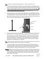
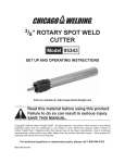
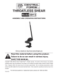
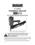
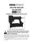
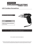
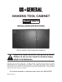
Hanging tool cabinet
Model 39213
Installation Instructions
Visit our website at: http://www.harborfreight.com
Read this material before using this product.
Failure to do so can result in serious injury.
Save this manual.
Copyright© 2001 by Harbor Freight Tools®. All rights reserved. No portion of this manual or any artwork
contained herein may be reproduced in any shape or form without the express written consent of
Harbor Freight Tools. Diagrams within this manual may not be drawn proportionally. Due to continuing
improvements, actual product may differ slightly from the product described herein. Tools required for
assembly and service may not be included.
For technical questions or replacement parts, please call 1-800-444-3353.
Manual Revised 10e
Save This Manual
Keep this manual for the safety
warnings and precautions, assembly,
operating, inspection, maintenance and
cleaning procedures. Write the product’s
serial number in the back of the manual
near the assembly diagram (or month and
year of purchase if product has no number).
Keep this manual and the receipt in a safe
and dry place for future reference.
4.
Store idle equipment. When not
in use, tools must be stored in a dry
location to inhibit rust. Always lock up
tools and keep out of reach of children.
5.
Stay alert. Watch what you are doing,
use common sense. Do not operate
any tool when you are tired.
6.
Check for damaged parts. Before
using any product, any part that
appears damaged should be carefully
checked to determine that it will
operate properly and perform its
intended function. Any part that is
damaged should be properly repaired
or replaced by a qualified technician.
7.
Replacement parts and accessories.
When servicing, use only identical
replacement parts. Use of any other
parts will void the warranty. Only use
accessories intended for use with this
product.
8.
Do not excessively overload the
shelves.
9.
Never use the Hanging Cabinet as a
seat, a stool or a ladder.
Specifications
Overall Dimensions
14-1/4” x 23-5/8” x
7-7/8”
Metal Thickness
19 Gauge
Compartment Dimensions
23-3/4” x 15-3/4”
Shelf Dimensions
15-3/8” x 15-1/2”
Door Dimensions
14-15/16” x 22-1/16”
Max. Weight Capacity
20 lb. per shelf
Number of Shelves
6
Number of Compartments
3
Keys
6
Number of 3” Peg Hooks
6
Safety Warnings and
Precautions
10. Use eye protection. Wear ANSIapproved impact safety goggles when
assembling.
WARNING: When using this product, basic safety precautions should Warning: The warnings, cautions, and
instructions discussed in this instruction
always be followed to reduce
manual cannot cover all possible
the risk of personal injury and
conditions and situations that may
damage to equipment.
occur. It must be understood by the
Read all instructions before using this
operator that common sense and
product!
caution are factors which cannot be
built into this product, but must be
1. Avoid working alone. If an accident
supplied by the operator.
happens, an assistant can bring help.
2.
Keep work area clean. Cluttered
areas invite injuries.
3.
Keep children away. Children must
never be allowed in the work area. Do
not let them handle machines, tools, or
extension cords.
SKU 39213
For technical questions, please call 1-800-444-3353.
REV 01i, 04c
Page 2
Assembly
Your Hanging Tool Cabinet, will require complete assembly as described in the
following steps. To assist you with assembly and operation, please refer to the Operational
Figures as well as the Parts List and Assembly Diagram located on the last pages of this
manual.
Right Side Panel (#7)
Bolts (#6)
Bottom Panel (#12)
Lip
Figure 1-Attaching Bottom Panel to Right Side Panel
1.
Lay out the Bottom Panel (part #12) on your work area with the Lip facing toward what
will be the front of the Hanging Tool Cabinet. Attach the Right Side Panel (#7) to the
Bottom Panel (#12) making certain that the lip faces the front of the Hanging Cabinet.
The lip should line up with the lip of the Bottom Panel (#12)-see Figure 1. Insert two
(2) Bolts (#6) up through the Bottom Panel (#12) then thread the Nut (#5) onto the Bolt
(#6). Repeat for the Left Side Panel (#16).
2.
Set the Hanging Tool Cabinet so that the Back Panel (#8) will be supported against a
workbench, wall or floor. Lay the edge of one (1) Back Panel
(#8) inside and at the rear of the Bottom Panel (#12)-see
Figure 2. Repeat for the remaining two (2) Back Panels (#8).
3.
The Center Panel 2 (#3) has a split/double lipBack
see Figure 3, next page. Set Center Panel 2 (#3) Panel
(#8)
so that the split lip faces the front of the Hanging
Cabinet. The back edge of Center Panel 2 (#3)
will lay on the edge of the rear right Back Panel (#8).
4.
Insert one Bolt (#6) through each hole in the edge of the right
Back Panel (#8), through the holes in the Center Panel 2 (#3)
and through the holes in the middle Back Panel (#8). Thread
Nut (#5) onto Bolt (#6).
Figure 2
Note: Back Panels (8) do not bolt to Side Panels (7 & 16) directly,
Back Panels (8) only bolt together and to the Top and Bottom Panels (1 & 12).
5.
Set the Center Panel 1 (#2) so that the lip faces front and the rear edge sits against
the back of the Bottom Panel (#12). Insert one Bolt (#6) through each hole in the
edge of the left Back Panel, through the holes in the Center Panel 1 (#2) and through
the holes in the middle Back Panel (#8). Thread Nut (#5) onto Bolt (#6).
REV 01i
SKU 39213
For technical questions, please call 1-800-444-3353.
Page 3
Note: Each Door is labeled indicating Right Door, Left Door, and Center Door.
6.
Loosely set the Top Panel (#1) in place on top of the assembly you finished in steps
one (1) through five (5) above. Make certain that the lip faces the front of the Hanging
Cabinet. Insert the Right Door (#11) into the holes in the Top and Bottom Panel. The
Doors are attached with pins which set into holes; make certain to lay the Washer
(hardware bag) over the pin prior to insertion. Insert the Center Door (#13) into the
holes in the Top and Bottom Panel. Repeat for the Left Door (#15).
7.
Once the Doors are in place, attach the Top Panel (#1) to the assembly by inserting
two (2) Bolts (#6) down into the Right Side Panel (#7) and two Bolts (#6) down into the
Left Side Panel (#16). Secure in place with Nuts (#5). Thread in remaining three (3)
Bolts (#6) through the Top Panel (#1) and into Center Panel 1(#2) and Center Panel 2
(#3), and into center Back Panel (#8). Secure with Nuts (#5).
Large Nut
Washers
Screw
Key
Lever
Figure 3-Center Panel
Figure 4-Inserting Lock
8.
Remove the large Nut off of the Lock (#14). Force the Lock (#14) into the hole in the
Right Door (#11). Thread the large Nut back onto the Lock until it rests against the
Door, securing the Lock (#14) in place-see Figure 4. Remove the washer and starshaped lock washer from the Lock by loosening the screw on the end-see Figure 4.
Slip on the locking lever so that when the key is turned the lever is horizontal, and
then replace the washer and lock washer onto the Lock (#14)-see Figure 4 above.
Repeat for the remaining two (2) Locks (#14).
Note: Each Lock (#14) comes with two (2) keys. Turning the key should move the lever to
a horizontal position which will keep the Door from opening.
9.
To hang the Cabinet, attach the two (2) Hangers (#4) to the right and left sides of
the Back Panel (#8) with two (2) Bolts (#6). The Hangers (#4) should be attached to
the Back Panel (#8) at different ends of the Cabinet so that when hung the weight is
evenly distributed. Hang the Cabinet with the one (1) hole in each Hanger.
Warning: Make certain that the Bolt you use (not included) is sufficiently strong enough to
hold the weight of the Hanging Cabinet and all contents of the cabinet. Make certain
that the surface to which the Cabinet will be mounted will support the full weight of
the Hanging Cabinet along with the weight of all tools and accessories which will be
placed inside of the Cabinet.
REV 01i, 03j
SKU 39213
For technical questions, please call 1-800-444-3353.
Page 4
Note: Make sure that the rear
lip of each Shelf can slip into the
tabs located on the sides of the
Back Panel (8).
Rear lip of Shelf
Figure 5
10. Each Shelf (#10) sits in the tabs on the Back Panel (8) and the tabs on the Side
Panels (7, 16) - see Figure 5.
Assembly Diagram
17
REV 01i, 02j, 04c, 07e
SKU 39213
For technical questions, please call 1-800-444-3353.
Page 5
Unpacking
When unpacking your Hanging Tool Cabinet, check to make sure the following parts are included. If any parts
are missing or broken, please call HARBOR FREIGHT TOOLS at 1-800-444-3353.
Parts Listing (Assembly Diagram located on page 5)
Part
Description
Q’ty
Part
Description
Q’ty
1
Top Panel
1
10
Shelf
6
2
Center Panel 1
1
11
Right Door
1
3
Center Panel 2
1
12
Bottom Panel
1
4
Hanger
2
13
Center Door
1
5
Nut
22
14
Lock
3
6
Bolt
22
15
Left Door
1
7
Right Side Panel
1
16
Left Side Panel
1
8
Back Panel
3
17
Peg Hook, 3”
6
Note: Some parts are listed and shown for illustration purposes only and are not available
individually as replacement parts.
PLEASE READ THE FOLLOWING CAREFULLY
THE MANUFACTURER AND/OR DISTRIBUTOR HAS PROVIDED THE PARTS DIAGRAM IN THIS MANUAL
AS A REFERENCE TOOL ONLY. NEITHER THE MANUFACTURER NOR DISTRIBUTOR MAKES ANY
REPRESENTATION OR WARRANTY OF ANY KIND TO THE BUYER THAT HE OR SHE IS QUALIFIED TO
MAKE ANY REPAIRS TO THE PRODUCT OR THAT HE OR SHE IS QUALIFIED TO REPLACE ANY PARTS
OF THE PRODUCT. IN FACT, THE MANUFACTURER AND/OR DISTRIBUTOR EXPRESSLY STATES
That ALL REPAIRS AND PARTS REPLACEMENTS SHOULD BE UNDERTAKEN BY CERTIFIED AND
LICENSED TECHNICIANS AND NOT BY THE BUYER. THE BUYER ASSUMES ALL RISK AND LIABILITY
ARISING OUT OF HIS OR HER REPAIRS TO THE ORIGINAL PRODUCT OR REPLACEMENT PARTS
THERETO, OR ARISING OUT OF HIS OR HER INSTALLATION OF REPLACEMENT PARTS THERETO.
REV 01i, 02j, 04c, 07e
SKU 39213
For technical questions, please call 1-800-444-3353.
Page 6