1
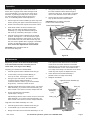
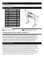
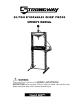
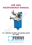
Owner’s Manual & Safety Instructions
Save This Manual Keep this manual for the safety warnings and precautions, assembly,
operating, inspection, maintenance and cleaning procedures. Write the product’s serial number in the
back of the manual near the assembly diagram (or month and year of purchase if product has no number).
Keep this manual and the receipt in a safe and dry place for future reference.
Visit our website at: http://www.harborfreight.com
Email our technical support at: [email protected]
REV 14i
When unpacking, make sure that the product is intact
and undamaged. If any parts are missing or broken,
please call 1-888-866-5797 as soon as possible.
Copyright© 2009 by Harbor Freight Tools®. All rights reserved.
No portion of this manual or any artwork contained herein may be reproduced in
any shape or form without the express written consent of Harbor Freight Tools.
Diagrams within this manual may not be drawn proportionally. Due to continuing
improvements, actual product may differ slightly from the product described herein.
Tools required for assembly and service may not be included.
Read this material before using this product.
Failure to do so can result in serious injury.
SAVE THIS MANUAL.
Specifications
Up to 12 Gauge Sheet Metal at 18″
Up to 16 Gauge Sheet Metal at 36″
Bending Capacity
Up to 16 Gauge Mild Steel at 18″
(Gauge x Width)
Up to 20 Gauge Mild Steel at 36″
Up to 22 Gauge Stainless Steel
Bend Angles
0 to 120°
Max. Box Depth
3″
Max. Beam Lift
7/8″
IMPORTANT SAFETY INFORMATION
1. Do not exceed the maximum bending capacities
of 18” wide stock (for 12 gauge steel) or
36” wide stock (for 16 gauge steel.)
2. Wear ANSI-approved safety goggles and
heavy-duty work gloves during assembly.
3. Keep fingers clear of Press Plate (14) and
Press Plate Assembly (17) during use.
4. Assemble only according to these instructions.
Improper assembly can create hazards.
5. Place only on a flat, stable surface able
to support weight of Metal Brake, item
being bent, and the bending force.
6. Verify that installation surface has no hidden
utility lines before drilling the holes.
7. Keep assembly and work area clean and well lit.
8. Keep bystanders out of the area
during assembly and use.
9. Do not assemble when tired or when under the
influence of drugs, alcohol or medication.
10. This product is not a toy. Do not allow
children to play with or near this item.
11. Use as intended only.
12. Inspect before every use; do not use
if parts are loose or damaged.
13. Maintain product labels and nameplates. These carry
important safety information. If unreadable or missing,
contact Harbor Freight Tools for a replacement.
Assembly and Installation Instructions
WARNING! The weight of the Brake and Stand requires
that two people assist in the assembly and installation.
1. Place the Metal Brake (back side) on the floor
with the mounting feet facing forward.
2. Place the Left Brake Stand (20) mounting pad
against the left mounting foot of the Brake.
Bolt (12)
Nut (10)
and Washer
(11)
Left and Right
Brake Stands
(19, 20)
3. Assemble with Bolt (12), Washer (11), and Nut (10)
as shown in Figure A. Securely tighten.
4. Mount the Right Brake Stand (19)
as described in Step 2.
5. Using two people, carefully lift the
Brake and Stand it upright.
6. Place the Brake and Stand in the location where it will
be mounted to the floor, then mark through the 1/2 inch
holes in the Left and Right Brake Stands (20 and 19).
CAUTION! Before drilling the mounting holes, verify that you
will not be drilling through any utility lines or water pipes.
7. Drill four mounting holes into the floor
and secure the Brake with four bolts*,
lock washers, and nuts (not supplied).
Body (18)
Figure A
*Use expansion anchor bolts for concrete floors.
For wooden floors, use lag bolts.
Page 2
For technical questions, please call 1-888-866-5797.
Item 91012
Operation
CAUTION! Do not attempt to bend stock which is
thicker than 12 gauge sheet metal. Damage could
occur to the Brake. If you are not sure of the stock
thickness, try bending a small piece of scrap stock.
If it does not easily bend, either the stock is too
thick, or the Bending Brake needs adjustment.
5. Using both hands, lift up on the Body using
its Lower Handles until the desired angle is
reached on the stock. Once bend is complete,
return Lower Handles to their down position.
1. Pull the upper Eccentric Handles (2) all the way down
before opening the upper Press Plate Assembly (17).
CAUTION! During bending, keep both
hands on the Lower Handles.
2. Scribe a line with pencil at point where stock is bent.
6. Lift the upper Eccentric Handles all the
way up and remove the sheet metal.
Press Plate Assembly (17)
3. Slide sheet metal to be bent in between the
Body (18) and under the Upper Press Plate
Assembly (17). Align the scribed bending line
with inner lip of the Body. See Figure 2, below.
4. Lift both Upper Eccentric Handles into the locked
position. See Figure 2. This will cause the upper
Press Plate Assembly to clamp down on the stock.
If the Handle does not come down all the way and
lock, the stock is greater than 12 gauge or the Brake
needs to be adjusted to allow for a thicker stock.
If so, refer to the Adjustments section below.
Body (18)
CAUTION! Keep spectators clear of
the work area during use.
Sheet
Metal
Upper
Eccentric
Handles
(2)
Lower Handles (1)
Figure B
Adjustments
Adjust the position of the Press Plate Assembly
to accommodate a thicker or thinner piece of
sheet metal, or to align it to the Body.
Adjusting for Thickness of Sheet Metal
1. Lift both Upper Eccentric Handles all the way up.
2. Loosen Nuts (7 and 5) to enable Bolt (6) to
move up or down. See Figure 3, above.
3. Using an open end wrench, turn Bolt clockwise
to lower the Press Plate Assembly, or
counterclockwise to raise it up (to accommodate
larger stock). Count the number of turns.
4. Adjust the Bolts with equal number of turns. The Press
Plate Assembly (17) must be flush with the Body (18)
when closed. If one side is not flush, readjust the side.
5. On the opposite side of the Brake,
repeat steps 1 through 4.
Adjust Bolt (6) with the same number of turns. The Press
Plate Assembly (17) must be flush with the Body (18)
when closed. If one side is not flush, readjust that side.
This adjustment will determine the roundness
of the bend. The farther back the Press Plate
Assembly, the rounder the bend. A typical setting
should be between 1/16 to 1/8 inch behind the
inner edge of the Body. The thickness of the sheet
metal may also require an adjustment here.
4. Check that the Press Plate Assembly is
parallel to the inner edge of the Body.
5. Retighten both Bolts.
Upper Eccentric Handles (2)
Bolt (16)
Press Plate
Assembly
(17)
Nut (5)
Body (18)
Bolt (6)
Left Turn
Nut (7)
Align the Press Plate Assembly In or Out
1. Lift both Upper Eccentric Handles all the way up.
2. Loosen Bolts (16) on each side of the Brake.
3. Nudge each side of the Press Plate Assembly in or out.
Item 91012
Figure C
For technical questions, please call 1-888-866-5797.
Page 3
Maintenance
1. Periodically lubricate all moving parts
and surface with a light oil.
2. Cover the Metal Brake when not in use.
Parts List and Diagram
Part
1
2
3
4
5
6
7
8
9
10
11
12
13
14
15
16
17
18
19
20
Description
Handle
Eccentric Handle
Slide Bearing
Cover
Nut (M14 x 1.5)
Bolt
Left Turn Nut (M14 x 1.5)
Lock Nut (M12)
Square Steel Holder
Nut (M10)
Washer (M10)
Bolt (M10 x 30mm)
Copper Cover
Press Plate Bracket
Washer
Bolt (M12 x 40 / GB5783)
Press Plate Assembly
Body
Right Brake Stand
Left Brake Stand
Qty
4
2
2
2
2
2
4
4
2
6
6
6
2
2
2
2
1
1
1
1
Record Serial Number Here:
Note: If product has no serial number, record
month and year of purchase instead.
Note: Some parts are listed and shown for
illustration purposes only, and are not available
individually as replacement parts.
PLEASE READ THE FOLLOWING CAREFULLY
THE MANUFACTURER AND/OR DISTRIBUTOR HAS PROVIDED THE PARTS LIST AND ASSEMBLY DIAGRAM
IN THIS DOCUMENT AS A REFERENCE TOOL ONLY. NEITHER THE MANUFACTURER OR DISTRIBUTOR
MAKES ANY REPRESENTATION OR WARRANTY OF ANY KIND TO THE BUYER THAT HE OR SHE IS
QUALIFIED TO MAKE ANY REPAIRS TO THE PRODUCT, OR THAT HE OR SHE IS QUALIFIED TO REPLACE
ANY PARTS OF THE PRODUCT. IN FACT, THE MANUFACTURER AND/OR DISTRIBUTOR EXPRESSLY
STATES THAT ALL REPAIRS AND PARTS REPLACEMENTS SHOULD BE UNDERTAKEN BY CERTIFIED AND
LICENSED TECHNICIANS, AND NOT BY THE BUYER. THE BUYER ASSUMES ALL RISK AND LIABILITY
ARISING OUT OF HIS OR HER REPAIRS TO THE ORIGINAL PRODUCT OR REPLACEMENT PARTS
THERETO, OR ARISING OUT OF HIS OR HER INSTALLATION OF REPLACEMENT PARTS THERETO.
Limited 90 Day Warranty
Harbor Freight Tools Co. makes every effort to assure that its products meet high quality and durability standards, and warrants
to the original purchaser that this product is free from defects in materials and workmanship for the period of 90 days from the
date of purchase. This warranty does not apply to damage due directly or indirectly, to misuse, abuse, negligence or accidents,
repairs or alterations outside our facilities, criminal activity, improper installation, normal wear and tear, or to lack of maintenance.
We shall in no event be liable for death, injuries to persons or property, or for incidental, contingent, special or consequential
damages arising from the use of our product. Some states do not allow the exclusion or limitation of incidental or consequential
damages, so the above limitation of exclusion may not apply to you. THIS WARRANTY IS EXPRESSLY IN LIEU OF ALL OTHER
WARRANTIES, EXPRESS OR IMPLIED, INCLUDING THE WARRANTIES OF MERCHANTABILITY AND FITNESS.
To take advantage of this warranty, the product or part must be returned to us with transportation charges prepaid. Proof of
purchase date and an explanation of the complaint must accompany the merchandise. If our inspection verifies the defect, we will
either repair or replace the product at our election or we may elect to refund the purchase price if we cannot readily and quickly
provide you with a replacement. We will return repaired products at our expense, but if we determine there is no defect, or that
the defect resulted from causes not within the scope of our warranty, then you must bear the cost of returning the product.
This warranty gives you specific legal rights and you may also have other rights which vary from state to state.