1
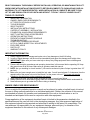
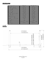
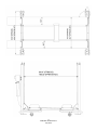
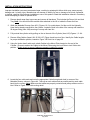
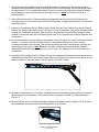
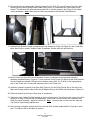
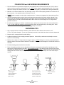
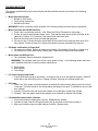
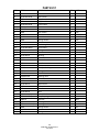
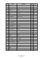
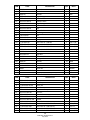
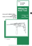
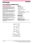
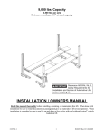
FP8K-DS & FP8K-DS-XLT
Four Post Parking Lifts
8,000 lbs. Capacity
(4,000 lbs. per axle)
INSTALLATION / OWNERS MANUAL
July 2015
READ THIS MANUAL THOROUGHLY BEFORE INSTALLING, OPERATING, OR MAINTAINING THIS LIFT.
WHEN DONE WITH INSTALLATION BE SURE TO RETURN DOCUMENTS TO PACKAGE AND GIVE ALL
MATERIALS TO LIFT OWNER/OPERATOR. WHEN INSTALLATION IS COMPLETE BE SURE TO RUN
LIFT UP AND DOWN A FEW CYCLES WITH AND WITHOUT “TYPICAL” VEHICLE LOADED ON LIFT.
TABLE OF CONTENTS
•
•
•
•
•
•
•
•
•
•
•
•
•
•
•
•
•
IMPORTANT INFORMATION
OWNER / EMPLOYER RESPONSIBILITY
LIFT SPECIFICATIONS & LAYOUT
TOOLS REQUIRED
SELECTING SITE
INSTALLATION INSTRUCTIONS
CASTER KIT ASSEMBLY / INSTALLATION
FOUNDATION & ANCHORING REQUIREMENTS
SAFETY INSTRUCTIONS & PROCEDURES
OPERATION INSTRUCTIONS
PREVENTIVE MAINTENANCE SCHEDULE
TROUBLESHOOTING
POWER UNIT PRIMING PROCEDURE
LATCH & CABLE INSPECTION / ADJUSTMENTS
EXPLODED VIEWS
PARTS LIST
WARRANTY POLICY
IMPORTANT INFORMATION
1. Always inspect the lift for damage and make note of any damage on the bill of lading.
2. In case of freight damage, call the truck line immediately and report the damage as a freight claim.
3. IMPORTANT! Make sure you have extra help or heavy duty lifting equipment when unloading and
assembling the lift.
4. Please read the safety procedures and operating instructions in this manual before operating lift. Keep
this manual near lift at all times. Make sure all operators read this manual.
5. NOTE: Are you installing in a level location? (Lift must be anchored in place if slope is greater than 1/8”
per foot.)
6. Make sure you have enough room to install the lock rods. You will need at least 6’ of clearance from the
opposite end of the power unit end of the lift and 6’ at the power unit end. The power unit may be
installed on the driver front or the passenger rear corner.
7. Never raise a car until you have double checked all bolts, nuts and hose fittings.
8. Always lower the lift to locks before going under the vehicle or storing another vehicle underneath lift.
9. Never allow anyone to go under the lift when raising or lowering.
OWNER / EMPLOYER RESPONSIBILITY
This is a vehicle lift installation/operation manual and no attempt is made or implied herein to instruct
the user in lifting methods particular to an individual application. Rather, the contents of this manual
are intended as a basis for operation and maintenance of the unit as it stands alone or as it is
intended and anticipated to be used in conjunction with other equipment.
Proper application of the equipment described herein is limited to the parameters detailed in the
specifications and the uses set forth in the descriptive passages. Any other proposed application of
this equipment should be documented and submitted in writing to the factory for examination. The
user assumes full responsibility for any equipment damage, personal injury, or alteration of the
equipment described in this manual or any subsequent damages.
2
FP8K-DS / FP8K-DS-XLT
July 2015
SPECIFICATIONS
Specifications
Lifting Capacity
Overall Length w/ Ramps
Overall Length/ No Ramps
Overall Width
Overall Height
Track Length
Track Width
Max Track / Position Width
Base Plate Size
Lifting Height
Width between Posts
Length between Post
Max Clearance / Under Track
Locking Positions
Lifting Speed
Power
Ship Weight
FP8K-DS
8000lbs
207-1/8”
175-1/2”
103-1/2”
86-1/4”
165-1/2”
18-5/8”
74-3/4”
10” x 12”
74-3/4”
94-1/2”
157-1/2”
70”
10
90S
110V-15 Amp / 1PH
1,690 lbs.
LAYOUT
3
FP8K-DS / FP8K-DS-XLT
July 2015
FP8K-DS-XLT
8000lbs
222-1/2”
190-5/8”
109-1/2”
96”
180-1/2”
18-5/8”
80-5/8”
10” x 12”
82-1/4”
100-5/16”
172-1/2”
78”
12
100S
110V-15 Amp / 1PH
1,785 lbs.
4
FP8K-DS / FP8K-DS-XLT
July 2015
TOOLS REQUIRED
Set of Metric Wrenches and/or Sockets
Chalk Line
Adjustable Wrench
Flat Screwdriver
Locking Pliers
Hex-Key / Allen Wrench Set
25’ Tape Measure
Needle Nose Pliers
Step Ladder
Rotary Hammer Drill (If anchoring)
Hammer
3/4" Masonry Bit (If anchoring)
Crow Bar
3 Gallons of Hydraulic Oil*
4 Foot Level
*Recommended Oil: ISO 32 Light Hydraulic Oil
SELECTING SITE
Before installing your new lift, check the following.
OVERHEAD OBSTRUCTIONS: The area where the lift will be located should be free of overhead
obstructions such as heaters, building supports, electrical lines etc.
FLOOR REQUIREMENTS: Visually inspect the site where the lift is to be installed and check for cracked or
defective concrete. This lift must be installed on a solid level concrete floor with no more than 2 degrees of
slope. A level floor is suggested for proper installation and level lifting. If a floor is of questionable slope,
consider a survey of the site and/or the possibility of pouring a new level concrete slab. This lift is designed to
be installed on a minimum of 4" thick, 3500psi, with steel reinforced concrete. Do not install this lift on asphalt,
wood, or any other surface other than described. This lift is only as strong as the foundation on which it is
installed.
NOTE: This Lift does not require bolting to the floor (BUT) If you choose the option to anchor the Lift to the
floor, please follow the detailed instructions in the manual and criteria above.
DO NOT install this lift outdoors unless special consideration has been made to protect the power unit from
weather conditions. The Power unit is not water proof!!!
DO NOT install lift close to wall. It is necessary to leave adequate clearance for safely walking. Suggest
clearance be 1 meter (3 feet) at min.
5
FP8K-DS / FP8K-DS-XLT
July 2015
INSTALLATION INSTRUCTIONS
Improper installation can cause accelerated wear, resulting in catastrophic failure which may cause property
damage and / or bodily injury. Manufacturer will assume no liability for loss or damage of any kind, expressed
or implied, resulting from improper installation or use of this product. Read this installation manual in its entirety
before attempting to install or operate the lift.
1. Remove plastic wrap from top runway and remove all hardware. This includes the Power Unit and Jack
Tray. Note: You should find this manual either attached to the Lift or inside the Power Unit box.
2. While the Mainside Runway (Item # 51) Figures 1 & 3 is upside down, find the end of the Hydraulic
Hose that is already connected to the cylinder. Locate the hole in the side of the runway and install the
90 degree fitting (Item # 86) securing to runway with Jam Nut.
3. Fully extend the cylinder rod by pulling on the on the end of the Cylinder (Item # 56) Figures 1, 3 & 4.
4. Remove lifting Cables (Items # 94, 95, 96 & 97) Figure 4 and layout on floor. Identify the Cable lengths
for proper installation position, based on Figure 4 & Parts List on page 25.
5. Using the ‘button head’ cable ends, attach Cables to the Mount Plate located on the end of the
Cylinder. Ensure to anchor the Cables to the Mount Plate using the Lock Plate to lock Cables into
position. Double check to ensure Cables are properly installed for routing.
6. Locate the four cable ends and route the appropriate Cable through each hole in corners of the
Mainside Runway, shown in Figure # 4. Take up as much cable slack as possible and lay each cable
back into the runway. Note: Make sure that cables are properly routed around pulleys and are not in a
bind. Refer to Figure 4 for Cable routing detail.
6
FP8K-DS / FP8K-DS-XLT
July 2015
7. Unbolt the top runway (Mainside) from the shipping brackets at each end of the runway, taking the
necessary safety precautions (using some type of a hoist is recommended), as this runway will need to
be flipped over so it is no longer upside down. Place this runway in your bay with the hydraulic fitting
facing toward your previously chosen corner for the power unit. Note: be careful not to pinch or
damage cables.
8. Next unbolt all four columns from the shipping package and place the column with the power unit
mounting bracket in the chosen corner noted in previous steps. Arrange the other three columns in the
remaining corners.
9. Unpack the Crossbeams, Ramps, Safety Latch Linkage Rods and Lock Ladders from bottom Runway.
Remove the Safety Latch covers (Item # 14) Figure # 1 from Crossbeams. They will be reinstalled later.
Arrange the Crossbeams so that the Safety Latches / threaded Bolt for the Locking Linkage is facing
outward to ensure that both of the Connecting Rods (Item # 70) Figure #2 are closest to the power unit
side columns.
10. If you have means for securely lifting the Crossbeam (Item # 67) Figure # 2, lower it into the tops of the
columns. If you don’t, then the columns will have to be placed horizontal on the floor, and the
Crossbeam installed in the columns. Then the entire end structure (two columns and a cross rail) will
need to be stood up as one. Note: Make sure to install Crossbeams so that the Safety Latches /
threaded Bolt are facing to outside of the lift, once stood up. The Cables will run on the inside of the
Crossbeams.
11. Unpack the Lock Ladders (Item # 5) Figure # 1 from the package and slide them into the precut slot on
the Rub Blocks (Item # 56) inside each column. After removing the top nut from the lock ladder you are
ready to install the Top Caps (Items # 3 & 4) Figure # 1 onto the columns.
12. Be aware of the offset hole in Top Caps. Arrange them so that the cable mounting holes are closest to
the runways. Use provided bolts, nuts, washers, and lock washers to install Top Caps as shown in
Figure # 1.
13. Secure Top Cap and Lock Ladder assemblies together with Washer and Nut (Items # 7 & 8). Position
the Crossbeams at the second lowest locking position on all columns.
7
FP8K-DS / FP8K-DS-XLT
July 2015
14. Stand-up and arrange the two end structures (Columns & Crossbeams) so that the outside of the cross
rail to the outside of the cross rail measurements are close. Compare the measurements from the left
and the right until they are diagonally within 1/2”. The 1/2” variance will help in mounting the runways.
15. Carefully lift and position each Runway into place and secure with the provided Hex Bolts (Item # 44),
mounting Plate (Item # 42) and hardware (Items # 45, 46 & 47) as shown in Figure # 1. The lift will
square itself as you further assemble it. Note: Install the Offside Runway (Item # 52) opposite from the
Mainside Runway (Item # 51) and Power unit Column as shown in Figure # 1.
8
FP8K-DS / FP8K-DS-XLT
July 2015
16. Route and mount the appropriate Cable(s) (Items # 94, 95, 96 & 97) to each Column Top Cap, while
ensuring that the small, spring loaded Cable Pulley (Item # 41) is between the Cable and the Lock
Ladder. This will allow the secondary slack cable lock to function properly. See Figure # 4 for Cable
routing installation. Note: Make sure all Cables are properly routed around Cable Sheaves.
17. Install all Lock Rods & Linkage components per the drawing on (Page 18) Figure #2. Also, install Eye
bolts (Item # 69) to outside / middle of each Crossbeam. Secure each bolt with Hex Nut.
18. Mount Power Unit (Item # 62) to the Mainside Column w/ attached mounting bracket using the
hardware provided shown in Figure # 3. Once mounted, fill the Power Unit reservoir tank with hydraulic
fluid and install the Hydraulic Fittings, Nuts & Washer (Items # 90, 91, 92 & 93) to the high pressure
port on the Power Unit. Connect the electrical power to the Power Unit.
19. Install the “braded” Hydraulic Hose (Item # 89) Figure # 3 to the Fitting (Item # 86) on the side of the
Main side Runway and the other end to the 90 degree fitting on the Power Unit as shown in Figure # 3.
20. Raise unit and set on the locks. Place level on crossbeam.
21. Tighten the Lock Ladder Rod Nut located on the top of each posts. This will raise the corner of the lift to
adjust for leveling. Each post has this adjustment. Place level on each runway and crossbeam and
check for proper levelness. Adjust to level the lift. Note: You may have to loosen the Nut under the
Top Plate to make leveling adjustments.
22. After leveling is complete, tighten the Nut on the Lock Rod, located underneath the Top Cap on each
post. This will lock the Lock Ladder in position.
9
FP8K-DS / FP8K-DS-XLT
July 2015
23. Raise lift off all locks until cables are supporting the lift. Adjust the Cable Nylon Lock Nut (Item # 99)
located on the top of each post until lift is level on crossbeams and runways. This will ensure the lift
travels up and down level. Note: You may need to use locking pliers to hold the cable from turning
when adjusting the Nylon Nut. Ensure the threads are engaged through the nylon for each Nylon Nut.
24. Install the Plastic ‘drip’ Boards into the bracket slots on the underside of the Mainside Runway as
shown below.
25. Insert Wheel Stop Plates (Item # 43) at front end of Runways, as shown in Figure #1 & #5.
26. Install Drive-On Ramps (Item # 53). Note: The usage of additional Wheel Stop Plates are
recommended when lifting and/or storing a vehicle, with or without the Drive-On Ramps.
27. Install Jack Tray between the Runways.
NOTE: Lubricate ALL Cable Sheaves, Bearings and Shafts with grease prior to operating Lift.
The Lift Installation is now complete.
(See following pages for Caster Kit & Anchoring Instructions, if required)
CAUTION: Read Safety & Operation Instructions before operating lift.
10
FP8K-DS / FP8K-DS-XLT
July 2015
CASTER KIT ASSEMBLY / INSTALLATION
1. Install Caster Wheels (Item # 107) to Caster Frames (Item # 104) using hardware provided, shown in
Figure 5. NOTE: Hitch Pin and Hairpin Clip will be used to attach casters to lift in following steps. DO
NOT install Caster Kit at this time.
2. Raise the lift 2 ft. to 3 ft. high.
3. Place Caster Assemblies under crossbeams as shown below and in Figure 5. Secure with Hitch Pin
(Item #106) and Hairpin Clip (Item # 105).
4. Lower lift and the columns will automatically raise off the floor.
NOTE: This Lift does not require bolting to the floor (BUT) If you choose the option to anchor
the Lift to the floor, please follow the criteria & detailed instructions on next page.
11
FP8K-DS / FP8K-DS-XLT
July 2015
FOUNDATION and ANCHORING REQUIREMENTS
1. Concrete shall have compression strength of at least 3,000 PSI and a minimum thickness of 4-1/4” in order to
achieve a minimum anchor embedment of 3-1/4”. NOTE: When using the standard supplied 3/4” x 5-1/2” long
anchors, if the top of the anchor exceeds 2-1/4” above the floor grade, you DO NOT have enough embedment.
2. Maintain a 6” minimum distance from any slab edge or seam. Hole to hole spacing should be a minimum 6-1/2”
in any direction. Hole depth should be a minimum of 4-1/4”.
3. DO NOT install on asphalt or other similar unstable surface. Columns are supported only by anchoring to floor.
4. Using the horseshoe shims provided, shim each column base as required until each column is plumb. If one
column has to be elevated to match the plane of the other column, full size base shim plates should be used.
Torque anchors to 130 ft-lbs. Shim thickness MUST NOT exceed 1/2” when using the 5-1/2” long anchors
provided with the lift.
5. If anchors do not tighten to 130 ft-lbs. installation torque, replace the concrete under each column base with a
2’ x 2’ x 6” thick 3,000 PSI minimum concrete pad keyed under and flush with the top of existing floor. Allow
concrete to cure before installing lifts and anchors (typically 2 to 3 weeks).
ANCHORING TIPS
1. Use a concrete hammer drill with a carbide tip, solid drill bit the same diameter as the anchor, 3/4” (.775 to .787 inches diameter). Do not use excessively worn bits or bits which have been incorrectly sharpened.
2. Keep the drill in a perpendicular line while drilling.
3. Let the drill do the work. Do not apply excessive pressure. Lift the drill up and down occasionally to remove
residue to reduce binding.
4. Drill the hole to depth of 2” deeper than the length of anchor. NOTE: Drilling thru concrete (recommended) will
allow the anchor to be driven thru the bottom of foundation if the threads are damaged or if the lift will need to be
relocated.
5. For better holding power blow dust from the hole.
6. Place a flat washer and hex nut over threaded end of anchor, leaving the nut almost flush with the top of the
anchor bolt. Carefully tap anchor into hole. Do not damage threads. Tap anchor into the concrete until nut and
flat washer are against base plate. Do not use an impact wrench to tighten! Tighten the nut, two or three turns on
average after the concrete has cured (28-day cure). If the concrete is very hard only one or two turns may be
required.
Drill holes using 3/4”
carbide tipped
masonry drill bit per
ANSI standard
B94.12.1977
Clean hole.
Run nut down just
below impact section
of bolt. Drive anchor
into hole until nut and
washer contact base.
12
FP8K-DS / FP8K-DS-XLT
July 2015
Tighten nut with
Torque wrench to
130 ft.-lbs.
SAVE THESE INSTRUCTIONS
SAFETY INSTRUCTIONS
When using your garage equipment, basic safety precautions should always be followed, including the
following:
Read all instructions
Care must be taken as burns can occur from touching hot parts.
Do not operate equipment with a damaged cord or if the equipment has been dropped or damaged until it has been examined by a qualified service person.
Do not let a cord hang over the edge of the table, bench, or counter or come in contact with hot
manifolds or moving fan blades.
If an extension cord is necessary, a cord with a current rating equal to or more than that of the
equipment should be used. Cords rated for less current than the equipment may overheat.
Always unplug equipment from electrical outlet when not in use. Never use the cord to pull the plug
from the outlet. Grasp plug and pull to disconnect.
Let equipment cool completely before putting away. Loop cord loosely around equipment when storing.
To reduce the risk of fire, do not operate equipment in the vicinity of open containers of flammable
liquids (gasoline).
Adequate ventilation should be provided when working on operating internal combustion engines.
Keep hair, loose clothing, fingers, and all parts of body away from moving parts.
To reduce the risk of electric shock, do not use on wet surfaces or expose to rain.
Use only as described in this manual. Use only manufacturer’s recommended attachments.
ALWAYS WEAR SAFETY GLASSES. Everyday eyeglasses only have impact resistant lenses, they
are not safety glasses.
SAFETY PROCEDURES
Never allow unauthorized persons to operate lift. Thoroughly train new persons/employees in the use,
operation and care of lift.
CAUTION! Power unit operates at high pressure.
Remove passengers before raising vehicle.
Prohibit unauthorized persons from being in shop area while lift is in use.
Total lift capacity is 8,000 lbs (4,000 lbs. per axel). Do not exceed this capacity.
Prior to lifting vehicle, walk around the lift and check for any objects that might interfere with the
operation of lift and safety latches; tools, air hoses, shop equipment.
When approaching the lift with a vehicle, make sure to center the vehicle between the columns. Slowly
drive the vehicle up with someone outside the vehicle guiding the driver.
Prior to lowering vehicle, walk around the lift and check for any objects that might interfere with the
operation of lift and safety latches; tools, air hoses, shop equipment.
Slowly drive the vehicle on and off of the lift. Have someone outside the vehicle guide the driver.
CAUTION!
LUBRICATE ALL CABLE SHEAVES, BEARINGS, AND SHAFTS WITH GREASE PRIOR TO OPERATING
THE LIFT. LUBRICATE ALL ON AN ANNUAL BASIS.
Motors and all electrical components are not sealed against the weather and moisture. Install this lift in a
protected indoor location. Failure by the owner to provide the recommended shelter could result in
unsatisfactory lift performance, property damage, or personal injury.
13
FP8K-DS / FP8K-DS-XLT
July 2015
OPERATION INSTRUCTIONS
NOTE: ALWAYS CHOCK WHEELS AND SET PARKING BRAKE BEFORE LIFTING VEHICLE!
Read Safety & Operating Instructions procedures in Manual completely before operating lift.
Properly maintain and inspect lift in accordance to owner’ manual.
Do not operate a lift that is damaged or in need of repair.
Allow only authorized personnel in the lift bay.
Stay clear of lift when raising or lowering (no riders).
Keep hands and feet away from pinch points at all times.
Never override the lift operating and safety controls.
If a vehicle is suspected of falling, clear area immediately.
Do not rock vehicle while positioned on lift.
Always use safety jack stands when removing or installing heavy components.
Vehicle Loading:
Position vehicle on lift runways by having another person guide you onto the runways. Check for proper
weight distribution (center of gravity should be evenly distributed between columns).
Set vehicle parking brake and chock tires to prevent vehicle movement.
Use caution before lifting pickup trucks, sport utility and other type vehicles. The individual axle weight
capacity should not exceed 1/2 of lift capacity.
Make sure vehicle is neither front nor rear heavy.
Raising Lift:
Push up switch to raise lift until platform runways clear floor.
Stop and check for vehicle movement and vehicle weight distribution. If secure, raise to desired height.
Always lower the lift to the nearest lock position by pressing the lower lever to relieve the hydraulic
pressure and let the latch set tight in a lock position.
Never work under a lift that is not in the locked position.
Lowering Lift:
Clear all obstacles from under lift and vehicle, and ensure only lift operator is in the lift area.
Stay clear of lift and raise the lift off the safety locks.
Pull safety latch releases and press the lower lever to begin descent.
Ensure lift is fully lowered, and having another person guide you, carefully unload the lift by driving off
of the lift runways.
CAUTION!
PAY ATTENTION TO THE LOWERING SPEED OF ALL FOUR CORNERS. MAKE SURE THEY ARE
MOVING DOWN AT THE SAME SPEED. STOP LOWERING THE LIFT BY RELEASING THE LOWERING
LEVER ON THE POWER UNIT AND MOVING THE LOCK LEVER TO THE LOCK POSITION IF ANY
CORNER STOPS MOVING OR IS SLOWER IN DESCENT. ALWAYS LOCK THE LIFT BEFORE GOING
UNDER THE VEHICLE. NEVER ALLOW ANYONE TO GO UNDER THE LIFT WHEN RAISING OR
LOWERING.
NOTE: It is normal for an empty lift to lower slowly - it may be necessary to add weight. Read and adhere to
all WARNING, CAUTION and SAFETY INSTRUCTIONS labels on lift.
14
FP8K-DS / FP8K-DS-XLT
July 2015
PREVENTIVE MAINTENANCE SCHEDULE
The periodic Preventive Maintenance Schedule given is the suggested minimum requirements & minimum
intervals; accumulated hours or monthly period, whichever comes sooner.
Periodic maintenance is to be performed on a daily, weekly, and yearly basis as given in the following
paragraphs.
Do not modify the lift in any manner without the prior written consent of the manufacturer.
WARNING!! Failure to perform the daily pre-operational check can result in expensive property damage, lost
production time, serious personal injury, and even death. The safety latch system must be checked and
working properly before the lift is put to use.
Failure to heed this warning can result in death or serious injury, or damage to equipment. If you hear a noise
not associated with normal lift operation or if there is any indications of impending lift failure CEASE
OPERATION IMMEDIATELY! Inspect, correct and/or replace parts as required.
Daily Pre-Operation Check (8-Hours)
Check safety lock audibly and visually while in operation
Check safety latches for free movement and full engagement with rack.
Check hydraulic connections, and hoses for leakage.
Check cables connections bends, cracks-and for loose fittings.
Check for frayed cables in both raised and lowered position.
Check snap rings at all rollers and sheaves.
Check bolts, nuts, and screws and tighten if needed.
Check wiring & switches for damage.
Check floor for stress cracks near columns.
Check Lubrications on cable sheaves and shafts.
Weekly Maintenance (every 40-Hours)
IF LIFT IS ANCHORED TO FLOOR - Check anchor bolts torque to 130 ft-lbs for the ¾ in. anchor bolts.
Do not use an impact wrench to tighten anchor bolts.
Check floor for stress cracks near columns
Check hydraulic oil level.
Check and tighten bolts, nuts, and screws.
Check all cable sheaves/assembly for free movement or excessive wear on cable sheave shaft.
Yearly Maintenance
Lubricate the cable sheave shafts at least once a year, after the lift is in service.
Check for excessive wear of cable. Replace them if necessary.
Change the hydraulic fluid - operating temperature, type of service, contamination levels, filtration, and
chemical composition of fluid should be considered. If operating in dusty environment shorter interval
may be required.
15
FP8K-DS / FP8K-DS-XLT
July 2015
TROUBLESHOOTING
The common problems that may be encountered and their probable causes are covered in the following
paragraphs:
Motor Does Not Operate:
1. Breaker or fuse blown
2. Faulty wiring connections
3. Defective up button
WARNING!! Failure to properly relieve pressure in the following steps can cause injury to personnel.
Motor Functions but Lift Will Not Rise:
1. Power Unit is not priming correctly. (See Power Unit Prime Procedure on next page.)
2. A piece of trash is under release ‘down’ valve. Push handle down and push the up button at the
same time. Hold for 10-15 seconds. This should flush trash from valve.
3. Remove the check valve cover and clean ball and seat.
4. Oil level too low. Oil level should be at the MAX fill line located on the reservoir tank, when lift is
fully lowered. Ensure to lower lift to relieve all hydraulic pressure and add oil as required.
Oil Blows out Breather of Power Unit:
1. Oil reservoir overfilled. Relieve all pressure and siphon out hydraulic fluid until at a proper level.
2. Lift lowered too quickly while under a heavy load. Lower the lift slowly under heavy loads.
Motor Hums and Will Not Run:
1. Lift overloaded. Remove excessive weight from lift.
WARNING!! The voltages used in the lift can cause death or injury. In the following steps, make sure
that a qualified electrician is used to perform maintenance.
2. Faulty wiring
3. Bad capacitor
4. Low voltage
Lift Jerks Going Up and Down:
1. If the lift jerks while going up and down, it is usually a sign of air in the hydraulic system. Raise lift
all the way to top and return to floor. Repeat 4-6 times, ensuring not overheat power unit.
Oil Leaks:
1. Power Unit: if the power unit leaks hydraulic oil around the tank-mounting flange check the oil level
in the tank. The level should be two inches below the flange of the tank. A screwdriver can be used
as a “dipstick”.
2. Cylinder / Piston Rod: the rod seal of the cylinder is out. Rebuild or replace the cylinder.
3. Cylinder / Vent: the piston seal of the cylinder is out. Rebuild or replace the cylinder.
Lift makes Excessive Noise / Vibrates:
1. Cross beam ends are rubbing the columns. Readjustment needed.
2. Cylinder too tight, load lift half capacity and cycle up and down a few times to break in.
3. May have excessive wear on cable sheaves or shafts. Replace them.
16
FP8K-DS / FP8K-DS-XLT
July 2015
POWER UNIT PRIMING PROCEDURE
THE PROBLEM: Power unit runs fine but will not pump any fluid.
WARNING!! Failure to properly relieve pressure in the following steps can cause injury to personnel.
Step 1 – Locate the check valve, the flush plug to the left of the lowering valve.
Step 2 – Using an Allen wrench and shop towel – with shop towel in place to catch fluid – loosen the
check valve plug 2 ½ turns to allow it to leak.
Step 3 – Push the START button for one second, then release for three seconds. Repeat these steps
until unit starts pumping fluid.
Step 4 – Tighten the check valve plug.
YOUR POWER UNIT SHOULD BE PRIMED
17
FP8K-DS / FP8K-DS-XLT
July 2015
LATCH & CABLE INSPECTION / ADJUSTMENTS
WARNING!! Failure to perform routine inspections can lead to reduced service life, which could result in
property damage and/or personal injury. Check locking latches for proper operation. Inspect for worn or
missing parts. Replace worn or damaged parts and adjust as required.
Latch Mechanism Inspection
Latches and Latch Bar Alignment:
Check for proper latch operation on all four corners.
Observe locking latches during lift operation to ensure that all latches line up with slots in
latch bar located in all four columns. If not, relocate and/or re-shim columns.
Check slack cable devices for proper operation. Inspect for worn or missing parts. Replace
worn or damaged parts as required.
Observe both locking latches and slack cable devices during lift operation to ensure that all
latches line up with slots in latch bar located in all four columns.
Leveling – Cable & Lock Ladder Adjustments
A. Initial Adjustment
Adjust cable with lift fully lowered. Loosen jam nut and tighten nut on cable stud on top of
column until yoke end is raised 1/4” (6.4 mm) and back off nut one turn. Retighten jam nut.
Repeat for all four cables.
B. Final Adjustment
1. Load a typical vehicle on lift.
2. Raise lift as high as it will travel (full height). You should hear the locking latches click
through all latch slots simultaneously.
3. Lower lift onto top latch position.
4. Check clearance, starting with the right front column, use a straight edge to mark the
position of the yoke bottom on the column.
5. Raise lift to full height again. Mark second position. If gap between two marks is less than
2”, adjust locking latch bar to reach clearance of 2”. Repeat for the other three columns.
6. Adjust locking latch bar adjusting nut so that the bottom of the topmost latch bar slot is at
least 2” below locking latch. After adjustment, tighten jam nut underneath column top plate,
7. If entire 2” clearance cannot be attained by adjusting the locking latch bar, adjust the cable.
Turn cable adjusting nut to raise the locking latch 2” above bottom of latch bar slot. Tighten
cable jam nut.
8. Lower lift and remove vehicle.
9. Raise the lift to full height. LISTEN and WATCH as the first locking latch clicks into place.
Synchronize the other three columns with this column by adjusting their cables so all four
latches click at same time. Tighten jam nuts.
NOTE: When making changes to adjustment nuts on cable end or latch bar stud, always leave at least two
threads showing between nut and stud end. Latches may not click in at the same time when vehicle is being
raised but should be close. Be sure all four corners have passed the locking latch bar slot before lowering lift
on locking latches.
18
FP8K-DS / FP8K-DS-XLT
July 2015
EXPLODED VIEW
Figure 1
19
FP8K-DS / FP8K-DS-XLT
July 2015
EXPLODED VIEW
Figure 2
20
FP8K-DS / FP8K-DS-XLT
July 2015
EXPLODED VIEW
Figure 3
21
FP8K-DS / FP8K-DS-XLT
July 2015
EXPLODED VIEW
41
Figure 4
22
FP8K-DS / FP8K-DS-XLT
July 2015
EXPLODED VIEW
Figure 5
23
FP8K-DS / FP8K-DS-XLT
July 2015
PARTS LIST
ITEM
1
2
3
4
5
6
7
8
9
10
11
12
13
14
15
16
17
18
19
20
21
22
23
24
25
26
27
28
29
30
31
32
33
34
35
36
37
38
39
CODE
TT7B-100-01-00
TT7B-100-02-00
TT7B-100-04-00
TT7B-100-03-00
TT7B-100-05-00
GB41
GB6175
GB95
GB95
GB5781
GB93
GB41
TT7B-200-09A/B
GB93
GB818
TT7B-200-10
GB78
GB95
TT7B-200-11
TT7B-200-08
SF2518
GB93
GB818
SGM-802-08
GB5781
GB95
TT7B-200-14
GB95
TT7B-200-06
TT7B-200-05
TT7B-200-04
TT7B-200-07A/B
GB6170
TT7B-200-02
TT7B-200-03-00A/B
GB93
GB6170
TT7B-200-15
DESCRIPTION
Main column
Sub column
Top plate 1#
Top plate 2#
Latch ladder
Hex nut
Hex nut
Flat washer
Flat washer
Hex Bolt
Spring washer
Hex nut
Anchoring Bolt
Cover Plate
Spring washer
cross screw
Bushing
Inner-hex bolt
Flat washer
Spindle
Roller
Complex Bushing
Spring washer
Cross Bolt
Guiding plate
Hex Bolt
Flat washer
Nylon block
Flat washer
Spindle
Rod
Safety block
Torque spring
Hex Nut
Bushing
Locking block
Spring washer
Hex nut
Spring
24
FP8K-DS / FP8K-DS-XLT
July 2015
QTY
1
3
2
2
4
4
4
24
32
16
16
16
16
2*2
24
16
4
4
13
4
10
10
8
32
36
8
4
4
4
2*2
8
4
2*2
8
10
8
NOTE
M20
M20
D20
D12
M12X35
D12
M12
φ19
D6
M6X12
M8X12
D24
D6
M6X12
M8X35
D8
D20
M12
D8
M8
ITEM
40
41
42
43
44
45
46
47
48
49
50
51
52
53
54
55
56
57
58
59
60
61
62
63
64
65
66
67
68
69
70
71
72
73
74
75
76
77
78
79
CODE
TT7B-200-12-00
TT7B-200-13
DPF4-3.2-300-07-00
DPF4-3.2-300-06
GB5780
GB93
GB6170
GB95
TT7B-300-01-04
TT7B-300-01-05
TT7B-300-01-07
TT7B-300-02-00
TT7B-300-01-00
TT7B-500-04-00
GB91
DPF4-3.2-500-02
DPF4-3.2-500-04
DPF4-3.2-500-03
GB889
GB95
DPF4-3.2-600-00
GB5781
GB95
GB93
GB6170
TT7B-200-01-00
TT7B-500-02
TT7B-500-03
TT7B-500-01
DPF4-3.2-400-01-00
DPF4-3.2-400-04
DPF4-3.2-400-03
DPF4-3.2-400-11
DPF4-400-02-00
GB889
SI6TK
DPF4-3.2-400-09
DESCRIPTION
Spindle
Small roller
Plate
Baffle plate
Hex Bolt
Spring washer
Hex Nut
Flat washer
Spindle bushing 4
Spindle
Spindle bushing 3
Main runway
Sub runway
Approach ramp
Cotter pin
Pin
Hydraulic Cylinder
Plate
Block plate
Nut
Flat washer
Jack tray
Power unit
Hex Bolt
Flat washer
Spring washer
Hex Nut
Crossbeam
Connecting rod
Anchoring bolt
Connecting rod
Knob
Handle
Bushing
Connection Coupler
Connecting rod
Connecting rod
Nut
Bearing
Spacer
25
FP8K-DS / FP8K-DS-XLT
July 2015
QTY
4
4
4
4
8
8
8
2
4
2
1
1
2
2
1
1
1
1
1
1
1
4
2
2
2
2
1
1
2
2
1
1
8
8
4
NOTE
M18X100
D18
M18
D20
D5X60
M24
D24
M8X25
D8
D8
M8
L=2080
L=215
M6
M6
ITEM
80
81
82
83
84
85
86
87
88
89
90
91
92
93
94
95
96
97
98
99
100
101
102
103
104
105
106
107
ITEM
1
2
5
51
52
61
67
68
72
85
94
95
96
97
CODE
GB96
GB5781
GB6170
TT7B-400-03
TT7B-400-04-00
DPF4-3.2-500-10
DPF4-3.2-500-07
GB95
DPF4-3.2-500-06
DPF4-3.2-500-11
TPF4-500-05
TPF4-500-09
TPF4-500-08
TPF4-500-07
TT7B-500-03A
TT7B-500-03B
TT7B-500-03D
TT7B-500-04C
GB95
DPF4-500-12
GB5783
GB93
GB6170
GB95
DPF4-3.2-700-01-00
GB91
DPF4-3.2-700-02-00
CODE
DESCRIPTION
Flat washer
Hex Bolt
Hex Nut
Angle fitting
Throttle Valve
Hydraulic Hose
Angle fitting
Flat washer
Nut
Hydraulic hose
Tee fitting
Nut
Washer
Fitting
Steel cable A – FP8K-DS
Steel cable B – FP8K-DS
Steel cable D – FP8K-DS
Steel cable C – FP8K-DS
Flat washer
Tight Nut
Galvanized Bolt
Spring washer
Hex Nut
Flat washer
Dolly frame
Cotter Pin
Pin
Caster
Parts Differ for FP8K-DS-XLT model
TT-8138-100-01-00
TT-8138-100-02-00
TT-8138-100-05-00
TT-8138-300-02-00
TT-8138-300-01-00
DPF4-3.2-600-00T
TT-8138-200-01-00
TT-8138-500-02
DPF4-3.2-400-01-00K
DPF4-3.2-500-10K
TT-8138-500-03A
TT-8138-500-03B
TT-8138-500-03D
TT-8138-500-04C
DESCRIPTION
Main post
Assistant post
Safety bar
Main runway
Assistant runway
Tool box
Traverse beam
Connection rod - XLT
Handle
Hydraulic hose
Steel cable A – FP8K-DS-XLT
Steel cable B – FP8K-DS-XLT
Steel cable D – FP8K-DS-XLT
Steel cable C – FP8K-DS-XLT
26
FP8K-DS / FP8K-DS-XLT
July 2015
QTY
4
4
8
1
1
1
1
1
1
1
1
2
2
1
1
1
1
1
4
16
16
16
16
4
4
4
4
QTY
1
3
4
1
1
1
2
2
1
1
1
1
1
1
NOTE
D6
M6X30
M6
d14
26’ 9-7/8”
22’ 1-3/4”
8’ 10-5/8”
13’ 6-3/8”
D20
M10X35
D10
M10
D10
D4X50
6"
NOTE
L=2230
29’ 1/8”
23’ 10”
9’ 4-1/4”
14’ 6-3/8”
TUXEDO DISTRIBUTORS LIMITED WARRANTY
Structural Warranty:
The following parts and structural components carry a five year warranty:
Columns
Legs
Tracks
Arms
Carriages
Cross Rails
Uprights
Overhead Beam
Top Rail Beam
Swivel Pins
Limited One-Year Warranty:
Tuxedo Distributors, LLC (Tuxedo) offers a limited one-year warranty to the original purchaser of Lifts and Wheel
Service equipment in the United States and Canada. Tuxedo will replace, without charge, any part found defective in
materials or workmanship under normal use, for a period of one year after purchase. The purchaser is responsible for all
shipping charges. This warranty does not apply to equipment that has been improperly installed or altered or that has not
been operated or maintained according to specifications.
Other Limitations:
This warranty does not cover:
1. Parts needed for normal maintenance
2. Wear parts, including but not limited to cables, slider blocks, chains, rubber pads and pulleys
3. Replacement of lift and tire changer cylinders after the first 30 days. A seal kit and installation instructions will
be sent for repairs thereafter.
4. On-site labor
Upon receipt, the customer must visually inspect the equipment for any potential freight damage before signing clear on
the shipping receipt. Freight damage is not considered a warranty issue and therefore must be noted for any potential
recovery with the shipping company.
The customer is required to notify Tuxedo of any missing parts within 72 hours. Timely notification must be received to
be covered under warranty.
Tuxedo will replace any defective part under warranty at no charge as soon as such parts become available from the
manufacturer. No guarantee is given as to the immediate availability of replacement parts.
Tuxedo reserves the right to make improvements and/or design changes to its lifts without any obligation to previously
sold, assembled or fabricated equipment.
There is no other express warranty on the Tuxedo lifts and this warranty is exclusive of and in lieu of all other
warranties, expressed or implied, including all warranties of merchantability and fitness for a particular purpose.
To the fullest extent allowed by law, Tuxedo shall not be liable for loss of use, cost of cover, lost profits,
inconvenience, lost time, commercial loss or other incidental or consequential damages.
This Limited Warranty is granted to the original purchaser only and is not transferable or assignable.
Some states do not allow exclusion or limitation of consequential damages or how long an implied warranty
lasts, so the above limitations and exclusions may not apply. This warranty gives you specific legal rights and
you may have other rights, which may vary from state to state.
1905 N Main St Suite C, Cleburne, TX 76033
Ph 817-558-9337 / Fax 817-558-9740
27
FP8K-DS / FP8K-DS-XLT
July 2015