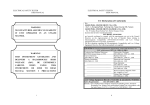
1
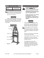
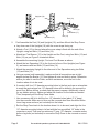
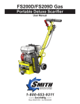
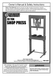
20 ton shop Press
37999
Set up and Operating Instructions
Distributed exclusively by Harbor Freight Tools®.
3491 Mission Oaks Blvd., Camarillo, CA 93011
Visit our website at: http://www.harborfreight.com
Read this material before using this product.
Failure to do so can result in serious injury.
Save this manual.
Copyright© 2009 by Harbor Freight Tools®. All rights reserved. No portion of this manual or any artwork
contained herein may be reproduced in any shape or form without the express written consent of
Harbor Freight Tools. Diagrams within this manual may not be drawn proportionally. Due to continuing
improvements, actual product may differ slightly from the product described herein. Tools required for
assembly and service may not be included.
For technical questions or replacement parts, please call 1-800-444-3353.
Manual Revised 09g
Save This Manual
Keep this manual for the safety
warnings and precautions, assembly,
operating, inspection, maintenance and
cleaning procedures. Write the product’s
serial number in the back of the manual
near the assembly diagram (or month
and year of purchase if product has no
number). Keep this manual and the
receipt in a safe and dry place for future
reference.
IMPORTANT SAFETY
INFORMATION
In this manual, on the labeling,
and all other information
provided with this product:
This is the safety alert
symbol. It is used to alert
you to potential personal
injury hazards. Obey all
safety messages that
follow this symbol to avoid
possible injury or death.
DANGER indicates
a hazardous
situation which, if not
avoided, will result in death or
serious injury.
WARNING
indicates a
hazardous situation which, if
not avoided, could result in
death or serious injury.
CAUTION, used
with the safety
alert symbol, indicates a
hazardous situation which, if
Page 2
not avoided, could result in
minor or moderate injury.
NOTICE is used to
address practices
not related to personal injury.
CAUTION, without
the safety alert
symbol, is used to address
practices not related to
personal injury.
WARNING Read all safety
warnings and instructions.
Failure to heed these markings
may result in personal injury
and/or property damage.
Save all warnings and
instructions for future
reference.
The warnings, precautions,
and instructions discussed
in this manual cannot cover
all possible conditions and
situations that may occur.
The operator must understand
that common sense and
caution are factors, which
cannot be built into this
product, but must be supplied
by the operator.
Work area
a.Keep the work area clean and
well lit. Cluttered benches and dark
areas increase the risks of electric
shock, fire, and injury to persons.
b.Do not operate the tool in
explosive atmospheres, such
as in the presence of flammable
liquids, gases, or dust. Air and
hydraulic tools create sparks which
may ignite the dust or fumes.
For technical questions, please call 1-800-444-3353.
SKU 37999
Personal safety
a.
b.
c.
d.
e.
Stay alert. Watch what you are
doing and use common sense
when operating the tool. Do not
use the tool while tired or under
the influence of drugs, alcohol, or
medication. A moment of inattention
while operating the tool increases the
risk of injury to persons.
Dress properly. Do not wear loose
clothing or jewelry. Contain long
hair. Keep hair, clothing, and
gloves away from moving parts.
Loose clothes, jewelry, or long hair
increases the risk of injury to persons
as a result of being caught in moving
parts.
Do not overreach. Keep proper
footing and balance at all times.
Proper footing and balance
enables better control of the tool in
unexpected situations.
Use safety equipment. Wear
heavy-duty work gloves during use.
Non-skid safety shoes and a hard
hat must be used for the applicable
conditions.
Always wear eye protection. Wear
ANSI-approved safety goggles,
heavy-duty work gloves, and steeltoe work boots during set up and/or
use.
Tool use and care
a.
Do not force the tool. Use the
correct tool for the application. The
correct tool will do the job better and
safer at the rate for which the tool is
designed.
SKU 37999
b.
Store the tool when it is idle out
of reach of children and other
untrained persons. A tool is
dangerous in the hands of untrained
users.
c.
Check for misalignment or binding
of moving parts, breakage of
parts, and any other condition
that affects the tool’s operation.
If damaged, have the tool serviced
before using. Many accidents are
caused by poorly maintained tools.
There is a risk of bursting if the tool is
damaged.
d.
Use only accessories that are
identified by the manufacturer for
the specific tool model. Use of an
accessory not intended for use with
the specific tool model, increases the
risk of injury to persons.
Service
a.
Tool service must be performed
only by qualified repair personnel.
b.
When servicing a tool, use only
identical replacement parts. Use
only authorized parts.
c.
Use only the lubricants supplied
with the tool or specified by the
manufacturer.
Specific Safety Rules
1.
Maintain labels and nameplates
on the Shop Press. These carry
important safety information. If
unreadable or missing, contact
Harbor Freight Tools for a
replacement.
2.
Keep hands away from arbor plates
and press rod during use.
For technical questions, please call 1-800-444-3353.
Page 3
3.
Do not move workpiece while
compressed.
4.
Release load before service or
maintenance.
5.
Bolt to floor before use.
6.
Keep area under arbor plates clear.
If arbor plates rest on obstruction
(i.e., bolt, debris, etc.), it creates an
uneven press, causing excess stress
and possible breakage.
7.
Do not stand directly in front of the
press when loaded. Do not leave the
press unattended when loaded.
17. Use only with bottle jack provided,
8.
Avoid off-center loads. Do not
operate if workpiece tilts or binds
during compression.
19. This product is not a toy. Keep it out
of reach of children.
9.
STOP and release compression
if you suspect imminent structural
failure. If safe, inspect thoroughly and
reposition before proceeding.
10. Do not compress springs or other
elastic objects. They could disengage
hazardously.
11. Keep bystanders out of work area.
12. 20 Ton Limit. Do not operate the
hydraulic jack beyond rated capacity.
13. Inspect before every use; do not use
if parts are loose or damaged.
the “Inspection, Maintenance, And
Cleaning” section of this manual.
Use of unauthorized parts or failure to
follow maintenance instructions may
create a risk of injury.
16. Only use with accessories rated to
handle the forces exerted by this tool
during operation. Other accessories
not designed for the forces generated
may break and forcefully launch
pieces.
18. Industrial applications must follow
OSHA requirements.
20. The warnings, precautions,
and instructions discussed in
this instruction manual cannot
cover all possible conditions and
situations that may occur. It must
be understood by the operator that
common sense and caution are
factors which cannot be built into this
product, but must be supplied by the
operator.
Save these
instructions.
14. Jack service must be performed
only by qualified repair personnel.
Service or maintenance performed by
unqualified personnel could result in
a risk of injury.
15. When servicing a jack, use only
identical replacement parts - refer to
attached, product-specific parts list
and diagram. Follow instructions in
Page 4
For technical questions, please call 1-800-444-3353.
SKU 37999
Specifications
Maximum
Capacity
Operating Instructions
Read the entire Important
Safety Information
section at the beginning of this
manual including all text under
subheadings therein before set
up or use of this product.
20 Tons
(40,000 pounds)
Oil Type
Hydraulic Jack Oil
Note: For additional information regarding
the parts listed in the following pages,
refer to the Assembly Diagram near
the end of this manual.
Inspect tool before use, looking
for damaged, loose, and
missing parts. If any problems
are found, do not use tool until
repaired.
Unpacking
When unpacking, make sure that the
item is intact and undamaged. If any parts
are missing or broken, please call Harbor
Freight Tools at 1-800-444-3353 as soon
as possible.
Components
Bottle Jack (1)
Press Rod (24)
Uprights (18)
Arbor Plates (20)
Press Apron (12)
Figure 1
SKU 37999
Assembly
1.
Using the Components photo (left)
and the Parts List and Diagram near
the end of the manual, lay out and
identify all pieces before assembly.
Note: All threaded ends of the fasteners
should face the interior of the press
or the back of the press, with the boltheads on the outside or front of the
press.
Have someone help you hold pieces
in place during assembly.
Finger tighten all nuts in step 2. Then
adjust the unit so that it is square,
and tighten all nuts and bolts before
bolting to the floor.
Finger tighten all nuts for the
remainder of the assembly. Then
adjust the unit so that it is square
and the Press Rod (24) has smooth
vertical travel. Securely tighten all
nuts and bolts.
For technical questions, please call 1-800-444-3353.
Page 5
Uprights (18)
Bolt (13)
Foot (16)
Foot Brace (17)
Figure 2
2.
Spreader (15)
Nut (14)
First Assemble the Feet (16) and Uprights (18), and then Mount the Shop Press:
a.Lay down one of the Uprights (18) with the cross straps facing up.
b.Attach a Foot (16) to the end where the cross strap is flush with the end of the
Upright, using two Bolts (13) and Nuts (14).
c. Attach two Foot Braces (17) to the Upright and the Foot, using four Bolts (13) and
Nuts (14), as per Figure 2 orientation above.
d.Assemble the remaining Upright, Foot and Foot Braces as above.
e.Attach the two Spreaders (15) to the foot-end of one of the Uprights (see Figure
2), and secure with two Bolts (13) and Nuts (14).
f. Attach the remaining Upright to the other end of the Spreaders using two Bolts
(13) and Nuts (14).
g.Using a square (sold separately), make sure that all connections are at right
angles (except the Braces (17)) and tighten all nuts and bolts in place. Determine
where you want to use the Press, and with assistance, move the unit to the
location where it is to be used.
h.If needed, drill four 1/2” diameter mounting holes in the feet and use as a template
to mark the spots where four 1/2” diameter holes will be drilled in the concrete or
wood floor. Before drilling, re-check that the press is square. Additionally, check
for any hidden wiring or cables and adjust the location for the holes as needed.
Then, temporarily set the Shop Press aside.
i. Use a masonry drill bit to drill the four 1/2” diameter holes (about 3”-4” deep)
into the concrete. Make sure to blow out the concrete dust from the drilled holes.
Insert Lag screw anchors (not included) into the holes.
j. Set the Shop Press back to the location where it is to be used, and align the four
1/2” diameter mounting holes in its feet with the four pre-drilled 1/2” holes in the
concrete or wood. Then use four minimum 3” long, 1/2” diameter, concrete anchor
bolts or lag bolts (not included) to secure the Shop Press to the concrete or wood
floor.
Page 6
For technical questions, please call 1-800-444-3353.
SKU 37999
the Upright (18). Position Header
Supports (25) at its sides, thread a
Bolt (10) through the Crossbeam,
Header Support, Top Crossbeam,
the other Header Support and out
through the other Upright. Attach Nut
(26). Repeat for the other end.
Bolts (13)
Press
Rod
Guides
(23)
Nuts
(14)
Figure 3
3.
Top
Crossbeam
(22)
Header (2)
Bottom Crossbeam (21)
Nut (26)
Bolt (6)
To Assemble the Crossbeams
(21/22):
Attach a Press Rod Guide (23) to
the center of the Top and Bottom
Crossbeams (21 & 22) by securing
in place with the Bolts (13) and Nuts
(14).
Nut (14)
Figure 5
5.
Header Supports (25)
Nut
(26)
Bolt
(11)
Nut
(9)
Header Supports (25)
To Attach the Header Supports (25)
to the Header (2):
Attach the four Header Supports (25)
to the sides of the Header (2) using
two Bolts (6) and Nuts (26). Insert
two Bolts (5) through the lower holes
at the top of the Header Supports and
secure with Nuts (14).
Bolt
(10)
Top
Crossbeam
(22)
Bolt (5)
Upright (18)
Bottom Crossbeam (21)
Press Apron (12)
Uprights (18)
Figure 4
4.
To Attach the Crossbeams (21/22)
and Header Supports (25) to the
Uprights (18):
a.Position one end of the Bottom
Crossbeam (21) with the second
hole at the top of the Upright and
secure with a Bolt (11) and Nut (9).
Repeat for the other end.
b.Position one end of the top
Crossbeam (22) at the top end of
SKU 37999
Figure 6
6.
Support Pins (19)
To install the Press Apron (12):
a.Slide the Support Pins (19) into the
holes in the Uprights (18).
b.Angle the Press Apron (12) so the
rails of the Press Apron straddle the
Uprights, then lower into place so
For technical questions, please call 1-800-444-3353.
Page 7
the Press Apron rests on the Support
Pins.
Bottle Jack (1) on the Press Rod
(24).
d.Slide the Press Rod up so the Bottle
Jack fits into the guide ring on the
Header (2).
Eye Bolts (7)
e.Hook the Springs (4) into the Eye
Bolts (7).
Nut (8)
f. Adjust the Eye Bolts so the
assembly is tight and secure.
Press Rod (24)
9.
Figure 7
7.
Insert the Eye Bolts (7) into the holes
in the Press Rod (24) and secure in
place with the Nuts (8).
Bolt (5)
Header (2)
Springs (4)
Tighten the Bolts and Nuts which
secure the Press Rod Guides (23),
making sure that the press Rod is
centered in them.
10. Place the Arbor Plates (20) on the
Press Apron (12).
Bleeding the Bottle Jack
Bottle
Jack
(1)
Handle (3)
Header
Supports (25)
Eye Bolts (7)
Elevating
Screw
(some models)
Saddle
Press
Rod
(24)
Figure 8
8.
Oil Fill Hole
Valve
Release
Screw
Press
Rod
Guides
(23)
To install the Bottle Jack assembly:
Figure 8
b.Hang the Springs (4) from the Bolts
(5) in the Header Supports (25).
c. Bleed the Bottle Jack (see Bleeding
the Bottle Jack, page 9) and make
sure it is fully collapsed. Center the
Oil Filler
Plug
IMPORTANT! Before first use,
check for proper hydraulic oil level
in the Jack. Then thoroughly test the
Jack for proper operation prior to its
actual use. If the Jack does not work
properly, bleed excess air from its
hydraulic system as follows:
a.Slide the Press Rod (24) through the
Press Rod Guides (23).
Page 8
Plunger/
Fulcrum
1.
Open the Release Valve.
For technical questions, please call 1-800-444-3353.
SKU 37999
2.
Remove the Oil Filler Plug and fill the
Jack with hydraulic fluid to the full
level.
3.
Apply pressure to the Saddle, and
pump the Handle (3) quickly several
times.
4.
Check the Oil Fill Hole and, if
necessary, top off the Oil Fill Hole
with hydraulic oil.
5.
Replace the Oil Filler Plug and close
the Release Valve.
6.
Test the Jack several times for proper
operation before putting into use.
If, after bleeding, the Jack still does
not appear to be working properly,
do not use the Jack until it has
been repaired by a qualified service
technician.
General Operating Instructions
The Shop Press can be used for
a variety of functions including
electric motor and armature
repair, installation and removal of
pressure fitted parts such as gears
and bearings, and bending or
straightening of metal. Care should
be taken in set up and operation of
the Shop Press to avoid damage or
injury.
To operate the Shop Press:
1.
Use the Support Pins (19) to adjust
the height of the Press Apron (12).
Note: The Press Apron (12) should be in
the highest position possible with the
workpiece as close as possible to the
ram of the Press Rod (24).
2.
Place the item to press between the
Arbor Plates (20).
WARNING: Make sure there is no
obstruction (such as a stray bolt or
debris) under the Arbor Plates. Such
items create an uneven surface
which can cause the Arbor Plates to
break under pressure.
WARNING: When pressing two items
together, the items must be lined
up vertically. If not, one item may
forcefully eject itself sideways from
the unit.
3.
SKU 37999
Using the Jack Handle (3), jack down
the Jack Plate until the ram of the
Jack Plate contacts your workpiece.
Make sure if you are pressing
two items together, that they are
in vertical alignment. Continue to
operate the Handle to press the work
piece.
For technical questions, please call 1-800-444-3353.
Page 9
4.
When the task is completed, be
careful when releasing Jack pressure.
For safety, remove the Handle, then
use the Handle to slowly turn the
Valve Release Screw on the Jack,
allowing the Jack Plate to rise.
User-Maintenance
Instructions
Procedures not specifically
explained in this manual
must be performed only by a
qualified technician.
WARNING: After pressing, during the
release process the Jack may rise
quickly. Stay clear.
To prevent
serious injury
from TOOL FAILURE:
Do not use damaged
equipment. If abnormal noise
or vibration occurs, have the
problem corrected before
further use.
1.
Before each use, inspect the
general condition of the Shop Press
and Bottle Jack. Check for broken,
cracked, or bent parts, loose or
missing parts, and any condition that
may affect the proper operation of the
product. If a problem occurs, have
the problem corrected before further
use.
Do not use damaged equipment.
2.
Before each use, thoroughly test
the Bottle Jack (1) for proper
operation prior to its actual use. If
the Bottle Jack appears not to be
working properly, follow Bleeding
instructions on page 9.
3.
Change the hydraulic oil at least
once every three years. To change
the hydraulic oil:
a.With the Jack fully lowered, unhook
the Springs from the Eye Bolts and
remove the Jack from the Shop
Press.
b.Remove the Oil Filler Plug.
c. Tip the Bottle Jack to allow the old
hydraulic oil to drain out of the unit
Page 10
For technical questions, please call 1-800-444-3353.
SKU 37999
completely, and dispose of the old
hydraulic oil in accordance with local
regulations.
d.Completely fill the unit with a high
quality hydraulic oil (not included)
until the oil just begins to run out of
the Oil Fill Hole.
e.Reinstall the Oil Filler Plug.
f. Clean with a clean cloth using a
detergent or mild solvent.
g.Replace the Bottle Jack onto the
Shop Press (See step 8 under
Assembly).
SKU 37999
For technical questions, please call 1-800-444-3353.
Page 11
x
Pump stroke
feels spongy
x
x
Troubleshooting
x
Unit may have too much hydraulic oil inside,
check fluid level and adjust if needed.
Valves may be blocked and may not close
fully. To flush the valves:
1. Lower the Saddle and securely close the
Release Valve.
2. Manually lift the saddle several inches.
3. Open the release valve and force the
saddle down as quickly as possible.
Jack may be low on oil. Check the oil level
and refill if needed.
Jack may require bleeding - see instructions
on page 6.
Check that Release Valve is closed fully.
POSSIBLE SYMPTOMS
PROBABLE Solution
Handle moves
(Make certain that the jack is not supporting a
Saddle will not
Oil leaking
load while attempting a solution.)
up when jack
lift all the way
from filler plug
is under load
Do not use a damaged or malfunctioning Jack!
To prevent serious injury:
Use caution when troubleshooting a malfunctioning jack.
Completely resolve all problems before use. If the solutions presented in the Troubleshooting guide do not
solve the problem, have a qualified technician inspect and repair the jack before use.
After the jack is repaired: Test it carefully without a load by raising it and lowering it fully, checking for
proper operation, Before returning the jack to operation.
X
X
Jack will not
Saddle
function at its
lowers under
weight capacity load
x
x
X
SKU 37999
For technical questions, please call 1-800-444-3353.
Page 12
parts list & ASSEMBLY DIAGRAM
Part
1
2
3
4
5
6
7
8
9
10
11
12
13
Description
Qty
Bottle Jack
Header
Jack Handle
Spring
Bolt M12 x 65
Bolt M18 x 70
Eye Bolt
Nut M8
Nut M16
Bolt M18 x 175
Bolt M16 x 155
Press Apron
Bolt M12 x 25
1
1
1
1
2
2
2
2
2
2
2
2
1
20
2
Part
14
15
16
17
18
19
20
21
22
23
24
25
26
3
Description
Nut M12
Spreader
Foot
Foot Brace
Upright
Support Pin
Arbor Plate
Bottom Crossbeam
Top Crossbeam
Press Rod Guide
Press Rod
Header Support
Nut M18
4
Qty
22
2
2
4
2
2
2
1
1
2
1
4
4
5
26
6
7
25
8
24
9
23
10
22
21
11
20
12
19
13
18
17
16
SKU 37999
15
For technical questions, please call 1-800-444-3353.
14
Page 13
PLEASE READ THE FOLLOWING CAREFULLY
The manufacturer and/or distributor has provided the parts list and assembly
diagram in this manual as a reference tool only. Neither the manufacturer or
distributor makes any representation or warranty of any kind to the buyer that
he or she is qualified to make any repairs to the product, or that he or she is
qualified to replace any parts of the product. In fact, the manufacturer and/
or distributor expressly states that all repairs and parts replacements should
be undertaken by certified and licensed technicians, and not by the buyer. The
buyer assumes all risk and liability arising out of his or her repairs to the
original product or replacement parts thereto, or arising out of his or her
installation of replacement parts thereto.
LIMITED 90 DAY WARRANTY
Harbor Freight Tools Co. makes every effort to assure that its products meet high
quality and durability standards, and warrants to the original purchaser that this product
is free from defects in materials and workmanship for the period of 90 days from the
date of purchase. This warranty does not apply to damage due directly or indirectly,
to misuse, abuse, negligence or accidents, repairs or alterations outside our facilities,
criminal activity, improper installation, normal wear and tear, or to lack of maintenance.
We shall in no event be liable for death, injuries to persons or property, or for incidental,
contingent, special or consequential damages arising from the use of our product.
Some states do not allow the exclusion or limitation of incidental or consequential
damages, so the above limitation of exclusion may not apply to you. This warranty
is expressly in lieu of all other warranties, express or implied,
including the warranties of merchantability and fitness.
To take advantage of this warranty, the product or part must be returned to us
with transportation charges prepaid. Proof of purchase date and an explanation of the
complaint must accompany the merchandise. If our inspection verifies the defect, we
will either repair or replace the product at our election or we may elect to refund the
purchase price if we cannot readily and quickly provide you with a replacement. We will
return repaired products at our expense, but if we determine there is no defect, or that
the defect resulted from causes not within the scope of our warranty, then you must
bear the cost of returning the product.
This warranty gives you specific legal rights and you may also have other rights
which vary from state to state.
3491 Mission Oaks Blvd. • PO Box 6009 • Camarillo, CA 93011 • (800) 444-3353
Record Product’s Serial Number Here:
Note: If product has no serial number, record month and year of purchase instead.
Note: Some parts are listed and shown for illustration purposes only, and are not
available individually as replacement parts.
Page 14
For technical questions, please call 1-800-444-3353.
SKU 37999