1
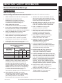
Table of contents
SAFETy
Safety ......................................................... 3
Specifications ............................................. 6
Setup .......................................................... 6
Operation ................................................... 11
Maintenance .............................................. 15
Parts List and Diagram .............................. 18
Warranty .................................................... 20
WARNING SyMBOLS AND DEFINITIONS
SETUp
This is the safety alert symbol. It is used to alert you to potential
personal injury hazards. Obey all safety messages that
follow this symbol to avoid possible injury or death.
Indicates a hazardous situation which, if not avoided,
will result in death or serious injury.
Indicates a hazardous situation which, if not avoided,
could result in death or serious injury.
Indicates a hazardous situation which, if not avoided,
could result in minor or moderate injury.
Addresses practices not related to personal injury.
OpERATION
MAINTENANcE
Page 2
For technical questions, please call 1-800-444-3353.
Item 61487
IMpORTANT SAFETy INFORMATION
SAFETy
General Tool Safety Warnings
Read all safety warnings and instructions.
Failure to follow the warnings and instructions may result in electric shock, fire and/or serious injury.
Save all warnings and instructions for future reference.
1. KEEP GUARDS IN PLACE and in working order.
2. REMOVE ADJUSTING KEYS AND
WRENCHES. Form habit of checking to
see that keys and adjusting wrenches are
removed from tool before turning it on.
12. SECURE WORK. Use clamps or a vise to hold
work when practical. It’s safer than using your
hand and it frees both hands to operate tool.
6. MAKE WORKSHOP KID PROOF with padlocks,
master switches, or by removing starter keys.
7. DON’T FORCE TOOL. It will do the job better
and safer at the rate for which it was designed.
8. USE RIGHT TOOL. Don’t force tool or attachment
to do a job for which it was not designed.
Table A: REcOMMENDED MINIMUM WIRE GAUGE
FOR EXTENSION cORDS
(120 VOLT)
(at full load)
EXTENSION cORD
LENGTH
25′
50′ 100′ 150′
0–6
18
16
16
14
6.1 – 10
18
16
14
12
10.1 – 12
16
16
14
12
12.1 – 16
14
12
Do not use.
9. USE PROPER EXTENSION CORD. Make sure your
extension cord is in good condition. When using
an extension cord, be sure to use one heavy
enough to carry the current your product will
draw. An undersized cord will cause a drop in line
voltage resulting in loss of power and overheating.
Table A shows the correct size to use depending
on cord length and nameplate ampere rating.
If in doubt, use the next heavier gauge.
The smaller the gauge number, the heavier the cord.
10. WEAR PROPER APPAREL. Do not wear
loose clothing, gloves, neckties, rings, bracelets,
or other jewelry which may get caught in moving
parts. Nonslip footwear is recommended.
Wear protective hair covering to contain long hair.
Item 61487
SETUp
5. KEEP CHILDREN AWAY. All visitors should
be kept safe distance from work area.
13. DON’T OVERREACH. Keep proper
footing and balance at all times.
14. MAINTAIN TOOLS WITH CARE. Keep
tools sharp and clean for best and safest
performance. Follow instructions for
lubricating and changing accessories.
15. DISCONNECT TOOLS before servicing;
when changing accessories, such as
blades, bits, cutters, and the like.
16. REDUCE THE RISK OF UNINTENTIONAL
STARTING. Make sure switch is in
off position before plugging in.
17. USE RECOMMENDED ACCESSORIES.
Consult the owner’s manual for recommended
accessories. The use of improper accessories
may cause risk of injury to persons.
18. NEVER STAND ON TOOL. Serious injury
could occur if the tool is tipped or if the
cutting tool is unintentionally contacted.
19. CHECK DAMAGED PARTS. Before further use
of the tool, a guard or other part that is damaged
should be carefully checked to determine that
it will operate properly and perform its intended
function – check for alignment of moving parts,
binding of moving parts, breakage of parts,
mounting, and any other conditions that may
affect its operation. A guard or other part that is
damaged should be properly repaired or replaced.
20. DIRECTION OF FEED. Feed work into
a blade or cutter against the direction of
rotation of the blade or cutter only.
21. NEVER LEAVE TOOL RUNNING UNATTENDED.
TURN POWER OFF. Don’t leave tool
until it comes to a complete stop.
For technical questions, please call 1-800-444-3353.
Page 3
OpERATION
4. DON’T USE IN DANGEROUS ENVIRONMENT.
Don’t use power tools in damp or wet locations,
or expose them to rain. Keep work area well lighted.
MAINTENANcE
3. KEEP WORK AREA CLEAN.
Cluttered areas and benches invite accidents.
NAMEpLATE
AMpERES
11. ALWAYS USE SAFETY GLASSES. Also use
face or dust mask if cutting operation is dusty.
Everyday eyeglasses only have impact resistant
lenses, they are NOT safety glasses.
Grounding Instructions
SAFETy
TO pREVENT ELEcTRIc SHOcK AND DEATH FROM INcORREcT GROUNDING WIRE
cONNEcTION
READ AND FOLLOW THESE INSTRUcTIONS:
110-120 V~ Grounded Tools: Tools with Three prong plugs
1. In the event of a malfunction or breakdown,
grounding provides a path of least resistance for
electric current to reduce the risk of electric shock.
This tool is equipped with an electric cord having an
equipment-grounding conductor and a grounding
plug. The plug must be plugged into a matching
outlet that is properly installed and grounded in
accordance with all local codes and ordinances.
SETUp
2. Do not modify the plug provided – if it will
not fit the outlet, have the proper outlet
installed by a qualified electrician.
3. Improper connection of the equipment-grounding
conductor can result in a risk of electric shock.
The conductor with insulation having an outer
surface that is green with or without yellow
stripes is the equipment-grounding conductor.
If repair or replacement of the electric cord or
plug is necessary, do not connect the equipmentgrounding conductor to a live terminal.
OpERATION
4. Check with a qualified electrician or service
personnel if the grounding instructions are
not completely understood, or if in doubt as
to whether the tool is properly grounded.
5. Use only 3-wire extension cords that
have 3-prong grounding plugs and 3-pole
receptacles that accept the tool’s plug.
6. Repair or replace damaged or
worn cord immediately.
Grounding
pin
125 V~ 3-prong plug and Outlet
(for up to 125 V~ and up to 15 A)
7. This tool is intended for use on a circuit that has
an outlet that looks like the one illustrated above in
125 V~ 3-prong plug and Outlet. The tool has a
grounding plug
that looks like the plug illustrated above
in 125 V~ 3-prong plug and Outlet.
8. The outlet must be properly installed and grounded
in accordance with all codes and ordinances.
9. Do not use an adapter to connect
this tool to a different outlet.
Drill press Safety Warnings
For your Own Safety Read Instruction
Manual Before Operating Drill press
1. Wear eye protection.
2. Do not wear gloves, necktie, or loose clothing.
MAINTENANcE
3. Clamp workpiece or brace against
column to prevent rotation.
4. Use recommended speed for drill
accessory and workpiece material.
5. The included chuck key is specially designed
to be self-ejecting, reducing the risk of ejecting
at high speed. Only use the included chuck
key or an identical replacement key.
Page 4
6. DO NOT OpERATE WITH ANy GUARD
DISABLED, DAMAGED, OR REMOVED. Moving
guards must move freely and close instantly.
7. The use of accessories or attachments not
recommended by the manufacturer may
result in a risk of injury to persons.
8. When servicing use only identical replacement parts.
9. Only use safety equipment that has been approved
by an appropriate standards agency. Unapproved
safety equipment may not provide adequate
protection. Eye protection must be ANSI-approved
and breathing protection must be NIOSH-approved
for the specific hazards in the work area.
For technical questions, please call 1-800-444-3353.
Item 61487
11. Industrial applications must follow OSHA guidelines.
12. Maintain labels and nameplates on the tool.
These carry important safety information.
If unreadable or missing, contact
Harbor Freight Tools for a replacement.
13. Avoid unintentional starting.
Prepare to begin work before turning on the tool.
14. People with pacemakers should consult their
physician(s) before use. Electromagnetic fields in
close proximity to heart pacemaker could cause
pacemaker interference or pacemaker failure.
15. WARNING: Some dust created by power
sanding, sawing, grinding, drilling, and other
construction activities, contains chemicals
known [to the State of California] to cause
cancer, birth defects or other reproductive harm.
Some examples of these chemicals are:
• Lead from lead-based paints
• Crystalline silica from bricks and cement or other
masonry products
• Arsenic and chromium from
chemically treated lumber
Your risk from these exposures varies,
depending on how often you do this type of work.
To reduce your exposure to these chemicals:
work in a well ventilated area, and
work with approved safety equipment, such
as those dust masks that are specially
designed to filter out microscopic particles.
(California Health & Safety Code § 25249.5, et seq.)
16. WARNING: Handling the cord on this product will
expose you to lead, a chemical known to the State
of California to cause cancer, and birth defects or
other reproductive harm. Wash hands after handling.
(California Health & Safety Code § 25249.5, et seq.)
17. The warnings, precautions, and instructions
discussed in this instruction manual cannot
cover all possible conditions and situations
that may occur. It must be understood by the
operator that common sense and caution are
factors which cannot be built into this product,
but must be supplied by the operator.
SETUp
10. Stay alert, watch what you are doing and use
common sense when operating a power tool.
Do not use a power tool while you are tired or
under the influence of drugs, alcohol or medication.
A moment of inattention while operating power
tools may result in serious personal injury.
SAFETy
Drill press Safety Warnings (cont.)
1. Anyone using vibrating tools regularly or for an
extended period should first be examined by a
doctor and then have regular medical check-ups
to ensure medical problems are not being caused
or worsened from use. Pregnant women or
people who have impaired blood circulation to
the hand, past hand injuries, nervous system
disorders, diabetes, or Raynaud’s Disease should
not use this tool. If you feel any medical or
physical symptoms related to vibration (such as
tingling, numbness, and white or blue fingers),
seek medical advice as soon as possible.
2. Do not smoke during use. Nicotine reduces
the blood supply to the hands and fingers,
increasing the risk of vibration-related injury.
3. Use tools with the lowest vibration when there
is a choice between different processes.
4. Include vibration-free periods each day of work.
5. Grip tool as lightly as possible (while still keeping
safe control of it). Let the tool do the work.
6. To reduce vibration, maintain the tool as
explained in this manual. If any abnormal
vibration occurs, stop use immediately.
MAINTENANcE
This tool vibrates during use. Repeated or
long-term exposure to vibration may cause
temporary or permanent physical injury,
particularly to the hands, arms and shoulders. To
reduce the risk of vibration-related injury:
SAVE THESE INSTRUcTIONS.
Item 61487
OpERATION
Vibration Safety
For technical questions, please call 1-800-444-3353.
Page 5
Specifications
Motor
Spindle Speeds
SAFETy
Spindle Stroke
Spindle Taper
Chuck Capacity
Swing
Table Diameter
Table Rotation
Table Tilt
Column Diameter
120VAC, 60Hz, 13.5A
220, 290, 360, 430, 500, 570, 640, 730, 810, 900,
1460, 1730, 1820, 2380, 2650, 3600 RPM
2-3/4"
MT2
7/64" to 5/8" (3mm to 16mm)
17″
12-7/8″
360°
45° (left and right)
3-3/16″
227541
SETUp
Setup - Before Use:
Read the ENTIRE IMpORTANT SAFETy INFORMATION section at the beginning of this
manual including all text under subheadings therein before set up or use of this product.
TO pREVENT SERIOUS INJURy FROM AccIDENTAL OpERATION:
Turn the power Switch of the tool off and unplug the tool from its electrical
outlet before performing any procedure in this section.
OpERATION
Note: For additional information regarding the parts listed in the following pages,
refer to the Assembly Diagram near the end of this manual.
Mounting
Before assembling and using the Drill Press,
secure the Base to a supporting structure.
1. Verify that the intended installation surface has no
hidden utility lines before drilling or driving screws.
2. Bolt the Base to a flat, level, solid floor
location capable of supporting the weight
of the Drill Press and any workpieces.
Assembly
column Assembly to Base
MAINTENANcE
1. Attach the Column Support (2) to the Base (1)
using the four M10x35 Bolts (5), four Spring
Washers (4) and four Flat Washers (3).
2. Tighten the Bolts firmly.
Note: It may be necessary to back the Set
Screws out beforehand, as they may protrude
into the Support tube, preventing the Column
from sliding fully into the Column Support.
3. Insert the Column (7) into the Support
and firmly secure this assembly in
place with the Set Screws (6).
Page 6
For technical questions, please call 1-800-444-3353.
Item 61487
1. Lubricate the Worm Gear (45) teeth with light grease
and insert the Gear shaft-first into the Table Support
(46). Extend the shaft as far as possible through the
opening in the side of the Support. See Figure A.
6. While holding the Rack and the Table Support
as assembled, slide both down onto the Column.
Slide the Rack down until the bottom of the Rack
is positioned against the Column Support.
7. Replace the Collar onto the Column with its beveled
side down, ensuring that the top end of the Rack
is engaged in the groove formed between the
Collar and the Column. IMpORTANT: Make sure
the Rack is not pinched and there is a working
clearance between the Rack and Collar.
SAFETy
Table to column
3. Use the Socket Head Cap Screw (44)
to attach the Table Crank Handle (43) to
the Table Crank. Use a hex key (not supplied)
to securely tighten the Crank Handle.
4. Loosen the Set Screw (16) in the Collar
(17) and remove the Collar and Rack (8)
from the Column. The Rack is stowed in
this position only for transit purposes.
5. With the long smooth end of the Rack upppermost,
slide the Rack down through the notch in the
opening in the Table Support, as shown in Figure B.
Engage the Rack into the Gear Mechanism
located on the inside of the Table Support.
9. Check the Collar for proper adjustment.
The Rack should move freely when the Table
is rotated the full 360º around the Column.
10. Screw the Table Lock Handle (36) into the Table
Support but do not tighten it all the way. Once
this is done, turn the Crank, testing to ensure
that the Table Support easily travels up and down
the full length of the Rack without binding, and
that the assembly and the Rack rotate freely all
the way around the Column without binding.
IF THE TABLE SUPPORT IS TOO TIGHT:
OpERATION
2. Insert the Table Crank (41) onto the protruding
Worm Gear shaft. Align the Table Crank′s Set
Screw (40) with the flat portion of the Worm
Gear shaft. Make sure the Worm Gear shaft
is inserted as far as possible into the Crank,
then tighten the Set Screw. See Figure A.
• Slightly loosen the Table Lock Handle
and loosen the Collar Set Screw.
• Adjust the Collar slightly to provide a
greater working clearance between
the Rack and the Collar.
• Tighten the Collar Set Screw, and test
the Table Support′s movement again.
MAINTENANcE
Figure A
Note: For the Rack to move easily when the
Table is rotated around on the Column, the
Collar must sit evenly on the Column and fit
loosely over the top of the Rack. Only tighten
the Collar Set Screw enough to keep the
Collar in place on the Column. Overtightening
the Set Screw may damage the Collar.
Figure B
Item 61487
SETUp
8. Tighten the Collar Set Screw.
For technical questions, please call 1-800-444-3353.
Page 7
Head Assembly to column
See Figure c.
SAFETy
1. Before installing the Head Assembly, it may be
necessary to back the four Socket Head Cap
Screws (6) out slightly to ensure they do not
protrude internally, as this would prevent the
Head Assembly from sliding fully into position.
2. With assistance, raise the Head assembly
and locate it on top of the Column.
3. Align the Head with the Base, and firmly
secure it with the Set Screws.
4. Screw the three Spindle Feed Handle Bars
(9) firmly into the Spindle Feed Hub (10).
Belt Tension
Lever (96)
Belt Tension
Locking Knob
(87)
Socket Head
cap Screws (6)
Figure c
Attaching the pulley cover Handle
SETUp
1. Slide the Pulley Cover Handle (118) into
the hole in the front of the Pulley Cover.
2. Put the Cross-Shape Screw (28) through the
Flat Washer (27) and twist it into the Handle
from the inside of the Pulley Cover.
Installing the cutting Oil System
1. Use four Socket Head Cap Screws (120) and four
Rubber Pads (88) to attach the two Oil Bottle Clips
(121) to the tapped holes in the left side of the Head.
2. Thread the Oil Pipe (76) into the bottom
of one of the Oil Bottles (56), screw an Oil
Bottle Cap (53) onto the Bottle and snap
the Bottle into the Oil Bottle Clips.
OpERATION
MAINTENANcE
Page 8
For technical questions, please call 1-800-444-3353.
Item 61487
Installing the Belts
IMpORTANT: Tension is correct when the belts
deflect by approximately 1/2″ at their centers of
run when using reasonable thumb pressure.
Deflection
Distance = 1/2"
SAFETy
1. Undo the Belt Tension Locking Knobs (87) on
both sides of the Head. Turn the Belt Tension
Lever (97) clockwise to bring the Motor Pulley
109) towards the Spindle Pulley (69), allowing
the Belts to be easily slipped over the Pulleys.
2. Lubricate the Idler Pivot Shaft (111) and
Idler Pulley (112) with light grease, and install
the Pivot Shaft in its mounting between
the Motor Pulley and Spindle Pulley.
3. Consult the chart inside the Pulley Cover
(or Figure F on page 12on page 9), and
install the Belts (70, 113) in the positions
corresponding to the required spindle/drill speed.
4. Turn the Belt Tension Lever counterclockwise
so that tension is applied to the belts.
Figure D
5. Use the Belt Tension Locking Knobs to
lock the Motor Pulley in this position.
1. Loosen the Table Lock Handle (36) and slide
the Table up the Column to within 6″ of the
Arbor (58). Tighten the Lock Handle.
2. Thoroughly clean the Arbor and the
tapered hole in the Chuck (57) of all dirt,
grease, oil, and protective coatings.
3. Slide the Chuck onto the Arbor.
5. Open the jaws of the Chuck to their
maximum, using the supplied Chuck Key.
6. Put a piece of scrap wood on the
table to protect the Chuck nose.
7. Using the Spindle Feed Handles, lower the Spindle
and press the Chuck nose hard against the
scrap wood on the table until the Chuck is forced
into a solid fit. The Chuck is pressure fitted.
MAINTENANcE
OpERATION
4. Examine the Chuck from all sides to
make sure that it is straight.
SETUp
Installing the chuck
Item 61487
For technical questions, please call 1-800-444-3353.
Page 9
Functions
SAFETy
SETUp
OpERATION
MAINTENANcE
Page 10
For technical questions, please call 1-800-444-3353.
Item 61487
Operating Instructions
SAFETy
Read the ENTIRE IMpORTANT SAFETy INFORMATION section at the beginning of this
manual including all text under subheadings therein before set up or use of this product.
Tool Set Up
TO pREVENT SERIOUS INJURy FROM AccIDENTAL OpERATION:
Turn the power Switch of the tool off and unplug the tool from its electrical
outlet before performing any procedure in this section.
TO pREVENT SERIOUS INJURy: DO NOT OpERATE WITH ANy GUARD DISABLED,
DAMAGED, OR REMOVED. Moving guards must move freely and close instantly.
Table Adjustment
4. Spin the Table about its axis by loosening
the Table Locking Handle (D).
SETUp
The Table is capable of moving in
four directions. See Figure E.
1. Raise or lower the Table by loosening the Table
Support Locking Handle (A) and turning the
Table Crank (C): clockwise to raise the Table
and counterclockwise to lower the Table.
2. Swivel the Table around the column by loosening the
Table Support Locking Handle. The table assembly,
arm and rack (B), move as one around the column.
OpERATION
3. Tilt the table by loosening the Bolt (E), and tilting the
Table to the required angle.
A scale (F) is provided on the arm to assist
in setting the required angle. For all normal
operations the Table angle should be set at 0°.
IMpORTANT: TO ENSURE THAT THE DRILL
IS ENTIRELY PERPENDICULAR TO THE
TABLE: Insert a piece of straight round bar in
the Chuck, place a square on the Table and
raise the table to bring the square up to the
round bar. Adjust the Table tilt if necessary
so that the Table is correctly aligned.
MAINTENANcE
Figure E: Table Adjustments
Item 61487
For technical questions, please call 1-800-444-3353.
Page 11
changing Drill Speed
4. Consult Figure F (or the chart inside the
Pulley Cover) and install the Belts on the
Pulleys in the positions that correspond
to the required Spindle/Drill speed.
See Functions on page 10 for illustrations.
SAFETy
1. WARNING! TO pREVENT SERIOUS
INJURy: Turn off and unplug the Drill
Press before changing drill speed.
2. Open the Pulley Cover.
3. Loosen the Belt Tension Lock Knobs
on both sides of the Head and turn the
Belt Tension Lever clockwise. This will bring
the Motor Pulley towards the Spindle Pulley,
removing all tension from the drive Belts.
5. When the Belts have been correctly positioned,
tighten them by turning the Belt Tension Lever
counterclockwise. The tension is correct when
the belts deflect by approximately 1/2″ at their
centers of run when using reasonable thumb
pressure. (See Figure D on page 9.) Lock this
position in with the two Belt Tension Lock Knobs.
Note: If a belt is too long to be properly
tensioned, it must be replaced.
SETUp
220
290
360
430
500
570
640
730
810
900
1460
1730
1820
2380
2650
3600
Figure F: Belt Speed Settings
Setting the Drilling Depth
OpERATION
See Figure G.
Located around the Spindle Feed Shaft is a Depth
Stop Collar (14) carrying a graduated scale.
The Collar will turn around the Shaft, and can
be locked in place by the Lock Knob (13).
Lock
Knob
(13)
1. With the power to the Drill Press switched OFF, use
the Spindle Feed Handles to lower the drill until the
bit contacts the workpiece and hold it in that position.
Depth Stop
collar (14)
2. Loosen the Lock Knob and turn the Depth Stop
Collar so that the measurement for the required
hole depth is aligned with the Pointer (23).
pointer (23)
3. Tighten the Lock Knob to lock
the Collar in this position.
Figure G: Setting the Drilling Depth
MAINTENANcE
Page 12
For technical questions, please call 1-800-444-3353.
Item 61487
1. Remove the upper Oil Bottle from the Oil
Bottle Clips and unscrew the Cap.
4. Open the Oil Pipe valve and adjust the Pipe
so the oil drips onto the cutting area.
2. Make sure that the Oil Pipe valve is closed.
Fill the Bottle with your lubricant of choice.
5. The used oil will collect in the Oil Bottle that is
attached to the underside of the Work Table.
3. Screw the Cap onto the Bottle and snap
the Bottle back into the Clips.
• Dispose of the used oil in accordance
with local regulations.
SAFETy
Using the cutting Oil Drip System
Installing the Bit
1. Loosen the Chuck with the Chuck Key until the jaws
of the drill are opened enough to fit the drill bit..
2. Insert the drill bit approximately 1″ into
the jaws of the Chuck, ensuring that the
jaws do not touch the flutes of the bit.
3. Hand tighten the Chuck until the bit is held
securely in place. Confirm that the bit is
centered between the Chuck jaws.
4. Use the Chuck Key to tighten the Chuck.
• Insert the tip of the Chuck Key into a hole on the
side of the Chuck so that the teeth on the Key
engage the gear on the Chuck. Use the Key to
tighten the Chuck securely and remove the Key.
NOTIcE: Use sharp bits. Dull, bent, or damaged
bits will cause stress on the drill and/or break.
SETUp
cAUTION! Wear heavy-duty work gloves to provide
protection when inserting and removing drill bits. Drill
bits become very hot during use. Do not remove a drill
bit until it has cooled.
Using the LED Lamp
1. Flip the LED Lamp Power Switch (73)
to turn the LED Lamp (72) on.
MAINTENANcE
OpERATION
2. Use the Lamp's built-in goose-neck to move it
to a position where it illuminates the workpiece
in the area where it is being drilled.
3. Turn off the Lamp after use. Move the
Lamp away from the Chuck before removing
the drill bit and cleaning the tool.
Item 61487
For technical questions, please call 1-800-444-3353.
Page 13
Workpiece and Work Area Set Up
SAFETy
1. Designate a work area that is clean and well-lit.
The work area must not allow access by children
or pets to prevent distraction and injury.
9. FOR FLAT WORK, lay the workpiece on
a wooden base and clamp it down firmly
against the table to prevent it from turning.
2. Route the power cord along a safe route to reach
the work area without creating a tripping hazard or
exposing the power cord to possible damage. The
power cord must reach the work area with enough
extra length to allow free movement while working.
10. FOR SMALL WORKPIECES that cannot be
clamped to the table, use a drill press vise (not
supplied). Clamp or bolt the vise to the table.
3. Secure loose workpieces using a vise or clamps
(not included) to prevent movement while working.
4. There must not be objects, such as utility lines,
nearby that will present a hazard while working.
5. Set the Table height and position so
that the drill travel range is sufficient
for the workpiece to be drilled.
11. WHEN DRILLING COMPLETELY THROUGH
WOOD, position a piece of scrap wood
between the workpiece and the table to prevent
splintering on the underside of the workpiece
as the bit breaks through. Brace one end
of the scrap wood against the left side of
the column (see Figure H). Securely clamp
the other end of the scrap wood to the table.
SETUp
6. Set the drilling depth (see Changing Drill
Speed on page 12) so that the bit will not
contact the table, or align the table so that
the hole in its center is in line with the bit.
7. Make sure the workpiece is securely clamped.
That is, held in a drill vise, or bolted to the table.
WARNING! Do not hold the workpiece
with your bare hands while drilling.
Serious injury may be caused if the workpiece
is flung out of the operator’s hand.
OpERATION
8. IF THE WORKPIECE IS IRREGULARLY SHAPED
and cannot be laid flat on the table, securely block
and clamp it. Any tilting, twisting or shifting will
result not only in a roughly drilled hole but also
increases the chances of damage to the drill.
Figure H: Bracing workpiece against column
General Operating Instructions
1. Use the Spindle Feed Handles to bring the drill bit
down to where the hole is to be drilled. Make minor
workpiece alignment adjustments as required.
2. Make sure that the Drill Press Power
Switch is in the ″Off″ position, then plug the
Power Cord into an electrical outlet.
MAINTENANcE
3. Turn the Drill Press on.
WARNING! If the drill bit grabs and spins the workpiece,
do not attempt to stop the spinning with your hands.
Step back, and turn the Drill Press off. Wait for the
Spindle to stop turning before dislodging the workpiece.
5. To prevent accidents, turn off the tool and
disconnect its power supply after use. Clean, then
store the tool indoors out of children’s reach.
4. Pull down on the Spindle Feed Handles and
slowly drill the hole into the workpiece.
Page 14
For technical questions, please call 1-800-444-3353.
Item 61487
Maintenance and Servicing
SAFETy
procedures not specifically explained in this manual must
be performed only by a qualified technician.
TO pREVENT SERIOUS INJURy FROM AccIDENTAL OpERATION:
Turn the power Switch of the tool off and unplug the tool from its electrical
outlet before performing any procedure in this section.
TO pREVENT SERIOUS INJURy FROM TOOL FAILURE:
Do not use damaged equipment. If abnormal noise or vibration
occurs, have the problem corrected before further use.
cleaning, Maintenance, and Lubrication
• misalignment or binding of moving parts,
• cracked or broken parts,
4. Apply paste wax to the Table and Tube Column to
enable movement and to help keep surfaces clean.
• damaged electrical wiring, and
5. All bearings are factory lubricated
and need no further attention.
• any other condition that may
affect its safe operation.
6. Periodically, lubricate the Rack teeth,
Table gears, and Spindle upper teeth.
2. AFTER USE, wipe external surfaces
of the tool with clean cloth.
7.
WARNING! If the supply cord of this
power tool is damaged, it must be replaced
only by a qualified service technician.
Belt Inspection and Tensioning
2. Replace belt if damaged, following the instructions
under Installing the Belts on page 9.
MAINTENANcE
1. Examine belt for cracks, tears in
the backing, and other damage.
SETUp
• loose hardware,
3. Using compressed air, blow clean the Table, Base,
and Motor cooling vents of dirt and materials.
OpERATION
1. BEFORE EAcH USE, inspect the general
condition of the tool. Check for:
Item 61487
For technical questions, please call 1-800-444-3353.
Page 15
Adjusting the Spindle Feed Handle Return Torsion Spring
This procedure must be performed only by a qualified technician.
SAFETy
Wear a full face shield during this procedure.
If the Spindle does not return all the way up or moves up
sluggishly, or if it requires too much force to pull down
on the Spindle Feed Handles, the amount of spring
tension on the Spindle Feed Handles can be adjusted.
1. Loosen the Lock Knob on the Depth Stop Collar.
2. Move the Spindle/Chuck assembly
to its uppermost position.
SETUp
3. Turn the Depth Stop Collar clockwise until it
stops, and tighten the Lock Knob to prevent
the Spindle/Chuck assembly from dropping
during Torsion Spring adjustment.
4. Insert a screwdriver in the lower-front notch
of the Spring Cap (78) to hold it in place.
7. Turn the screwdriver counterclockwise and
engage the next Spring Cap notch.
Hold the screwdriver in place.
8. Tighten the inner Nut just enough to
engage the Spring Cap notch.
Note: If this Nut is too tight, it will restrict the up-anddown movement of the Spindle/Chuck assembly.
9. Remove the screwdriver, pull down on the Spindle
Feed Handles and check the spring tension, making
sure the up movement is smooth and complete.
• From one inch down, the Chuck should return
to its uppermost position. If more tension
is required, repeat steps 4 through 9.
5. While holding the screwdriver in place, use a
wrench to remove only the outer Nut (77).
10. Replace the outer Nut and tighten it on top
of the inner Nut. Do not overtighten.
6. With the screwdriver still in place, loosen
the remaining (inner) Nut until the
Spring Cap notch disengages from the
Spring Retainer -- about 1/8 inch.
11. If the up/down movement is restricted,
slightly loosen the inner and outer Nuts,
then retighten only the outer Nut.
OpERATION
MAINTENANcE
Page 16
For technical questions, please call 1-800-444-3353.
Item 61487
Troubleshooting
Motor runs,
but Spindle
does not turn.
Performance
decreases
over time.
Excessive noise
or rattling.
Overheating.
Belt(s) improperly installed or missing.
Eliminate use of extension cord. If an extension cord
is needed, use one with the proper diameter for its
length and load. See Table A on page 3.
Properly install belt(s). See Installing
the Belts on page 9.
1. Accessory dull or damaged.
2. Carbon brushes worn or damaged.
1. Keep cutting accessories sharp. Replace as needed.
2. Have qualified technician replace brushes.
1. Internal damage or wear. (Carbon
brushes or bearings, for example.)
2. Belt (if equipped) too loose (slipping)
or too tight (bearing damage).
1. Forcing machine to work too fast.
2. Accessory dull or damaged.
3. Blocked motor housing vents.
1. Have technician service tool.
4. Motor being strained by long or
small diameter extension cord.
SAFETy
Tool operates
slowly.
3. Tool’s thermal reset breaker
tripped (if equipped).
4. Internal damage or wear. (Carbon
brushes or switch, for example.)
Extension cord too long or
wire size too small.
Likely Solutions
1. Check that cord is plugged in.
2. Check power at outlet. If outlet is unpowered,
turn off tool and check circuit breaker.
If breaker is tripped, make sure circuit is right
capacity for tool and circuit has no other loads.
3. Turn off tool and allow to cool.
Press reset button on tool.
4. Have technician service tool.
SETUp
possible causes
1. Cord not connected.
2. No power at outlet.
2. Properly tension belt.
1. Allow machine to work at its own rate.
2. Keep cutting accessories sharp. Replace as needed.
3. Wear ANSI-approved safety goggles and
NIOSH-approved dust mask/respirator while
blowing dust out of motor using compressed air.
4. Eliminate use of extension cord. If an extension cord
is needed, use one with the proper diameter for
its length and load. See Table A on page 3.
Follow all safety precautions whenever diagnosing or servicing
the tool. Disconnect power supply before service.
OpERATION
problem
Tool will
not start.
THE MANUFACTURER AND/OR DISTRIBUTOR HAS PROVIDED THE PARTS LIST AND ASSEMBLY DIAGRAM
IN THIS MANUAL AS A REFERENCE TOOL ONLY. NEITHER THE MANUFACTURER OR DISTRIBUTOR
MAKES ANY REPRESENTATION OR WARRANTY OF ANY KIND TO THE BUYER THAT HE OR SHE IS
QUALIFIED TO MAKE ANY REPAIRS TO THE PRODUCT, OR THAT HE OR SHE IS QUALIFIED TO REPLACE
ANY PARTS OF THE PRODUCT. IN FACT, THE MANUFACTURER AND/OR DISTRIBUTOR EXPRESSLY
STATES THAT ALL REPAIRS AND PARTS REPLACEMENTS SHOULD BE UNDERTAKEN BY CERTIFIED AND
LICENSED TECHNICIANS, AND NOT BY THE BUYER. THE BUYER ASSUMES ALL RISK AND LIABILITY
ARISING OUT OF HIS OR HER REPAIRS TO THE ORIGINAL PRODUCT OR REPLACEMENT PARTS
THERETO, OR ARISING OUT OF HIS OR HER INSTALLATION OF REPLACEMENT PARTS THERETO.
Record product’s Serial Number Here:
Note: If product has no serial number, record month and year of purchase instead.
Note: Some parts are listed and shown for illustration purposes only,
and are not available individually as replacement parts.
Item 61487
For technical questions, please call 1-800-444-3353.
Page 17
MAINTENANcE
pLEASE READ THE FOLLOWING cAREFULLy
parts List and Diagram
parts List
SAFETy
part
SETUp
OpERATION
MAINTENANcE
1
2
3
4
5
6
7
8
9
10
11
12
13
14
15
16
17
18
19
20
21
22
23
24
25
26
27
28
29
30
31
32
33
34
35
36
37
38
39
40
41
42
43
44
45
46
47
48
49
50
51
52
53
54
55
56
57
58
59
60
61
Page 18
Description
Base
Column Support
Flat Washer 10
Spring Washer 10
Bolt M10×35
Socket Head Cap Screw M10×10
Column
Rack
Spindle Feed Handle Bar
Spindle Feed Hub
Spring Pin 5×30
Spindle Feed Shaft
Lock Knob
Depth Stop Collar
Scale Label
Set Screw M6×10
Collar
Rivet
Toothed Washer 4
Flat Washer
Spring Washer 4
Screw M4×8
Pointer
Cover Plate
Flat Washer 4
Junction Box
Flat Washer 5
Cross-Shape Screw M5×8
Switch Panel
Drill Press Power Switch
Tapping Screw St3.5×10
Work Table
Rivet 2×3
Scale Label
“0”-Degree Label
Table Lock Handle
Handle Grip
Gear
Axis Pin
Set Screw M5×10
Table Crank
Nut M10
Table Crank Handle
Socket Head Cap Screw M8×90
Worm Gear
Table Support
Table Support Arm
Table Clamp
Table Clamp Handle
Spring Washer 16
Bolt M16×35
Sealing Gasket (B)
Oil Bottle Cap
Sealing Gasket (A)
Hollow Connecting Bolt
Oil Bottle
Chuck
Arbor
Spindle
Ball Bearing 6006
Spindle Sleeve
Qty
1
1
4
4
4
4
1
1
3
1
1
1
3
1
1
2
1
1
2
2
2
8
1
1
7
1
4
4
1
1
3
1
5
1
1
1
1
1
1
1
1
2
1
1
1
1
1
1
1
1
1
1
2
1
1
2
1
1
1
1
1
part
62
63
64
65
66
67
68
69
70
71
72
73
74
75
76
77
78
79
80
81
82
83
84
85
86
87
88
89
90
91
92
93
94
95
96
97
98
99
100
101
102
103
104
105
106
107
108
109
110
111
112
113
114
115
116
117
118
119
120
121
122
Description
Rubber Ring
Ball Bearing 6004
Retainer Ring 19
Retainer Ring 47
Ball Bearing 6205
Bearing Spacer Ring
Spindle Housing
Spindle Pulley
V-Belt A-785
Thin Nut M24×1.5
LED Lamp
LED Lamp Power Switch
LED Lamp Switch Panel
Nut M10x1.5
Oil Pipe
Nut M12x1.5
Spring Cap
Tension Spring
Screw
Power Cord
Nut M6
Cross-Shape Screw M6×10
Flat Washer 6
Wire Clamp(B)
Nut M4
Belt Tension Locking Knob
Rubber Pad
Pulley Cover
Machine Body (Head)
Spring Pin 8×20
Retainer 15
Jackstay (B)
Jackstay (A)
Cam
Pull Pin
Belt Tension Lever
Belt Tension Lever Handle
Wire Clamp(A)
Motor Base Plate
Nut M8
Spring Washer 8
Flat Washer 8
Nut M12
Spring Washer 12
Flat Washer 12
Motor
Bolt M8×25
Motor Pulley
Flat Key 5x25
Idler Pivot Shaft
Idler Pulley
V-Belt A-710
Ball Bearing 6202
Pulley Bushing
Retainer Ring 35
Protective Ring
Pulley Cover Handle
Protective Ring
Socket Head Cap Screw M6×10
Oil Bottle Clip
Motor Pulley Set Screw
For technical questions, please call 1-800-444-3353.
Qty
1
1
1
2
2
1
1
1
1
1
1
1
1
1
1
2
1
1
1
1
2
3
7
3
3
2
4
1
1
1
1
1
1
1
1
1
1
4
1
4
4
8
2
2
2
1
4
1
1
1
1
1
2
1
1
2
1
1
4
2
1
Item 61487
Assembly Diagram
116
71
114
SAFETy
115
70
114
69
113
112
68
111
66
85
67
22
25
117
84
28
27
120
88
81
53
56
65
25
22
73
31
6
18
20
29 28
23
26 22 21 24
104
92
13
83
96
97
98
105
106
12
11
15
25
16
22
17
107
10
14
9
8
37
62
33
36
35
50
51
46
47
48
16
58
53
57
54
40
49
41
42
43
44
39
38
7
MAINTENANcE
45
34
52
6
5
4
3
2
55
56
Item 61487
91
95
103
101 102 103
32
63
59
93 94
87
83 84 85
90
27
64
100
88
30
75
60
86
80
77
78 79 19
42
76
74
61
82
108
122
118
89
121 72
109
99
119
66
110
SETUp
83
OpERATION
65
1
For technical questions, please call 1-800-444-3353.
Page 19
Limited 90 Day Warranty
Harbor Freight Tools Co. makes every effort to assure that its products meet high quality and durability standards,
and warrants to the original purchaser that this product is free from defects in materials and workmanship for the
period of 90 days from the date of purchase. This warranty does not apply to damage due directly or indirectly,
to misuse, abuse, negligence or accidents, repairs or alterations outside our facilities, criminal activity, improper
installation, normal wear and tear, or to lack of maintenance. We shall in no event be liable for death, injuries
to persons or property, or for incidental, contingent, special or consequential damages arising from the use of
our product. Some states do not allow the exclusion or limitation of incidental or consequential damages, so the
above limitation of exclusion may not apply to you. THIS WARRANTY IS EXPRESSLY IN LIEU OF ALL OTHER
WARRANTIES, EXPRESS OR IMPLIED, INCLUDING THE WARRANTIES OF MERCHANTABILITY AND FITNESS.
To take advantage of this warranty, the product or part must be returned to us with transportation charges
prepaid. Proof of purchase date and an explanation of the complaint must accompany the merchandise.
If our inspection verifies the defect, we will either repair or replace the product at our election or we may
elect to refund the purchase price if we cannot readily and quickly provide you with a replacement. We will
return repaired products at our expense, but if we determine there is no defect, or that the defect resulted
from causes not within the scope of our warranty, then you must bear the cost of returning the product.
This warranty gives you specific legal rights and you may also have other rights which vary from state to state.
3491 Mission Oaks Blvd. • PO Box 6009 • Camarillo, CA 93011 • (800) 444-3353