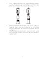
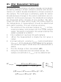
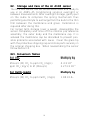
1
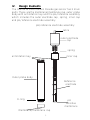
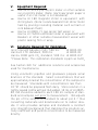
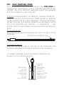
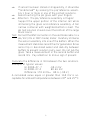
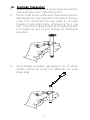
HI 410
CARB
ON DIO
XIDE
5
Instruction Manual
HI 4105
Carbon Dioxide
Ion
Selective Electrode
1
2
HI 4105 Carbon Dioxide Electrode
I. Introduction:
The Hanna HI 4105 Carbon Dioxide gas sensing electrode
is a combination electrode designed for the measurement
of Carbon Dioxide in aqueous solutions such as water, soft
drinks or wine, samples. Carbonate and Bicarbonate ions
are also measured by conversion to Carbon Dioxide gas
upon ISA addition.
II. Specifications
Type:
CO2 gas sensing
electrode with glass pH
internal, Ag/ AgCl
reference and gas
permeable membrane.
CO3 2-,HCO3- , CO2
Species detected:
-4
CO2 Measurement Range:
0.02 M to 4 x 10 M
880 to 17.6 ppm
Interfering ions:
SO2/SO32-, H2S/S2-
Operating Temperature:
0 to 40°C
Operating pH:
4-5 pH
Dimensions:
12 mm (OD) X 120
mm (insertion)
0.47”x 4.72”
Wetted materials:
Delrin®, body and cap
with PTFE membrane
Connection:
BNC
3
III. Theory of Operation
Operation::
The Carbon Dioxide electrode is a complete potentiometric
cell that contains both a silver/silver chloride (Ag/AgCl)
reference and a pH measurement element. These elements
are housed within a thermoplastic body in a chloride ioncontaining electrolyte, and are isolated from the sample by
a PTFE membrane.
ISA addition changes the pH of the sample to approximately 4.7 pH and Bicarbonate (HCO3-) and carbonate
(CO32-) ions in the sample are converted to carbon dioxide
(CO2). The CO2 in the sample solution diffuses through the
PTFE membrane where it dissolves into the thin film of fill
solution found between the membrane and the internal pH
membrane. Here it converts back into bicarbonate and
hydrogen ions. The pH changes proportionally with the
concentration of dissolved gas in the sample solution. Diffusion of CO2 continues until the partial pressures of the gas
in the sample and thin film are equal.
The Nernst expression for an Carbon Dioxide sensor is expressed in the equation below. Note that the potential is a
function of the Carbon Dioxide gas, which in turn is related
to the hydrogen ion concentration. The glass internal,
Ag/AgCl reference, equilibrium constant and Henry’s law
constant are rolled into the E’ and Eo terms. The Nernst
equation for the sensor becomes the equation noted below:
E = E’+2.3RT/nF log [CO2]= Eo+0.059 log [H+]
E = observed potential
E’ = Reference and fixed internal voltages
R = gas constant (8.314 J/K Mol)
n= Charge on ion (equivalents/mol)
T = absolute temperature in K
F = Faraday constant (9.648 x 10⁴ C/equivalent)
The mV should increase in a Nernstian manner as the
carbon dioxide partial pressure increases in the sample.
4
IV. Design Elements
The Hanna HI 4105 Carbon Dioxide gas sensor has 3 main
parts. These are the membrane/membrane cap, outer probe
body with antirotation key and the pH/reference assembly
which includes the outer electrode cap, spring, inner cap
and pH/reference electrode assembly.
pH/reference electrode assembly
cable
outer electrode
cap
spring
antirotation key
inner cap
Outer probe body
Reference
electrode
O-ring
pH
sensitive
membrane
Membrane/membrane cap
5
V. Equipment Required:
• Hanna HI 4222 pH/ISE/mV meter or other suitable
ion or pH/mV meter. (Note: log/linear graph paper is
useful if an ISE meter is not available).
• Hanna HI 180 magnetic stirrer or equivalent with
stirring bars. (Note: Isolate beakers from stirrer motor
heat by placing insulating material such as foam or
cork between them).
• Hanna HI 4000-71 gas sensor test vessel or
Hanna HI 76404 electrode holder or equivalent with
Beakers or other suitable measurement vessel with
plastic sealing film or wrap.
VI. Solutions Required for Calibration:
Ionic Strength Adjuster (ISA), 500 mL: HI 4005-00
Hanna 0.1 M standard, 500 mL:
HI 4005-01
Hanna 1000 ppm CO2 standard, 500 mL: HI 4005-03*
*Please Note: This calibration standards is ppm as CaCO3
See Section XVII for additional solutions and accessories
used for maintenance.
Using volumetric pipettes and glassware prepare serial
dilutions of the standard. Select concentrations that will
approximately bracket the concentration of the samples to
be measured. Standards with concentrations less than
10-3M should be prepared fresh daily. Store solution in a
tightly sealed bottle without ISA added. 10 mL of HI 400500 ISA should be added to each 100 mL sample of standard and samples just prior to measurement. ISA adjusts
the pH of the sample or standard to about pH 4.7 thus
converting carbonate and bicarbonate ion to carbon dioxide. It also provides samples and standards a constant
ionic strength background that stabilizes the solutions activity coefficient and permits concentration to be measured
directly.
6
VII
VII. General Guidelines
• Calibration standards and sample solutions should
have the same ionic strength. ISA should be added to
both samples and standards immediately before taking measurements.
• Calibration standards and sample solutions should be
stirred at the same rate using identical sized stir bars.
Stir thoroughly and continuously.
• Calibration standards and sample solutions should be
at the same temperature. Thermally insulate solution
vessel from magnetic stirrer with cork or other insulating medium.
• Wait until sensor value has stabilized before taking
reading (at least 5 minutes when going from more
dilute to more concentrated samples, longer when the
order is reversed).
• Surface coating on the PTFE membrane will effect the
response. Inspect sensor before using. Wash off with a
jet of deionized water or mild detergent to remove
film.
• Replace PTFE membrane if damage is evident or a
droplet of internal electrolyte is seen.
• Rinse electrode with distilled or deionized water between samples and dab dry with lab wipe or other soft
disposable absorbent toweling.
• Check calibration every 1-2 hours. Recalibrate if necessary.
• Position sensors at an angle of approximately 20° to
30° from verticle to reduce possibility of trapping gas
bubbles on on the membrane cap. Gas bubbles also
form from solution out-gassing due to temperature
change. Gently tap body of sensor to dislodge them.
• Close container with plastic wrap or use HI 4000-71
gas sensor test vessel to prevent gas from leaving.
• If electrode was left out in air for a prolonged period,
gently pulling cable will permit an exchange of fill
solution at the membrane surface. Re-Calibration is
required.
7
VIII. Inner Electrode Check
Prior to assembling the electrode for the first time or
subsquently reactivating it after extended periods of dry
storage, the inner electrode assembly should be hydrated
and then tested as a pH electrode.
Prepare pH test solutions HI 4000-47-4 and HI 4000-477 by mixing and dissolving each buffer packet in separate
containers with 50 mL deionized water. These pH solutions
contain chloride ions and pH buffers that are used to verify
the inner electrode (pH internal) is operational. See
Section XVII for replacement accessories and maintenance
items.
For a new sensor:
Remove the protective shipping cap from the glass inner
electrode.
Protective shipping cap
For existing sensor:
Unscrew the upper cap on the top of the electrode and
carefully withdraw the internal pH/reference assembly.
For stable readings, glass should be covered to the
bottom of the long black band.
Use test
tube or
graduated
cylinder
(weighed
Bottom) when
testing or
conditioning
pH internal
Test buffer
can be
used as a
conditioning
solution
for the
pH internal
8
•
If sensor has been stored or shipped dry, it should be
“conditioned” by soaking the pH/reference assembly 1 hour or more in one of the pH test solutions.
• Avoid touching the pH glass with your fingers.
• Attention: The pH/reference assembly is fragile!
Support the upper portion of the internal cell while
immersing the glass and reference assembly. A tall
narrow container with weighted bottom is best. The
pH test solution should cover the bottom of the large
black band.
Test: Connect the BNC connector on the electrode cable to a
pH/mV (mV or ORP mode) meter. Carefully immerse
the sensor assembly into one of the buffers. When the
measurment stabilizes record the mV generated. Rinse
sensor tip in deionized water and dab dry between
buffers to prevent solution carry-over. Do not rub the
glass. Take a measurement in the second buffer and
record mV. Pay attention to minus sign if present.
Calculate the difference in mV between the two solutions.
Example of typical values:
HI 4000-47- 7
-90.2 mV
HI 4000-47-4
80.66 mV
Difference 170.8 mV= 80.6-(-90.2)
A calculated value equal or greater than 160 mV is acceptable for ambient temperatures between 20° and 25°C.
9
IX. Electrode Preparation
1) Remove glass internal from sensor body and perform
inner electrode check. (See section VIII).
2) The HI 4105 sensor comes with three easily replaceable membrane caps (two which are spares). Remove
a cap from membrane box and screw on to lower
threads of outer probe body, compressing the o-ring
seal. Avoid touching working area of membrane with
your fingers as skin oil will change the membrane
properties.
3.) Using dropper provided, add about 2 mL of carbon
dioxide internal fill solution HI 4005-40 into outer
probe body.
10
4) Insert and position the inner glass/reference assembly into the outer body so that the anti-rotation key
sits in the cut out on the outer probe body.
CARBON DIOXIDE
HI 4105
CARBON DIOXIDE
HI 4105
5) Holding the electrode upright, slide spring and electrode cap down cable and screw cap on outer body
until fully engaged. Do not invert electrode. Do not
overtighten.
6) Install assembled electrode in gas sensor test vessel
or in electrode holder and connect cable connector to
pH/mV meter.
11
X. Quick Check of Electrode Slope
• Connect BNC (connector) to pH/mV/ISE meter.
• Place meter in mV mode.
• Place 100 mL of deionized water into a vessel with
stir bar. Add 10 mL of ISA Hanna HI 4005-00.
• Place sensor into prepared sample.
• Add 1 mL of 1000 ppm or 0.1 M Carbon dioxide
standard to beaker and stir sample. Wait approximately 5 minutes. Record the mV value when stable.
• Add an additional 10 mL of standard to the solution.
Record the mV when reading has stabilized (approximately 5 minutes). This value should be greater
than the previous noted (more positive).
• Determine the difference between the two mV values.
An acceptable value for this slope is 54±4 mV at
ambient temperatures between 20 and 25°C.
XI. Corrective action
• Verify standard has been properly added.
• Verify ISA has been added in the correct ratio to the
standard (1 part ISA to 10 parts sample or standard).
• Verify that the upper cap has been screwed in all the
way.
• Verify electrode is connected properly to meter and the
meter is is powered .
• Verify membrane cap is tightened securely to probe
body.
• Examine the membrane for discoloration or perforations or for internal fill solution that might have
leaked through the PTFE membrane. Replace membrane cap if damaged.
If drift is seen:
• Verify electrode and standards are at same temperature.
• Verify electrode has adaquate fill solution.
• Verify electrode was not left in air for prolonged period.
12
XII. Sample Handling
• For optimum results, allow samples and standards
and the HI 4105 electrode to reach the same temperature.
• As CO2 is volatile, measure samples immediately after collection.
• If sample must be stored: Completely fill collection
bottle with dilute samples and tightly cap container
to prevent carbon dioxide loss or contamination from
other sources.
• If sample must be stored: For acetic samples. add
sodium hydroxide (10N) to raise pH to 8-9 for storage. Tightly close collection bottle.
• If sample must be stored: keep sample at a lower
temperature than it was collected at until time of
measurement.
• Add Hanna HI 4005-00 ISA just prior to measurement to adjust standards and samples to a pH
between 4.2-5.2 for measurement. ISA must mix
thoroughly with solutions and time allowed to convert
carbonate and bicarbonate species to CO2 (dissolved).
• Covering sample and standards after adding ISA will
minimize carbon dioxide loss from the solution.
• Calibration standards and samples must be the same
ionic strength. The concentration for all dissolved species in a sample should not exceed 1M. Samples that
exceed this should be diluted with CO2 free deionized water. Do not reduce CO2 below 10-4M. Multiply
the final result by the corresponding dilution factor.
13
XIII. Direct Calibration and Measurement
The direct measurement method is best used in the linear
working regions of the sensor. (See figure for typical sensor
response) and can be used when measuring many samples.
A direct reading ISE meter (HI 4222 or equivalent) determines concentration of the unknown by a direct reading
after calibrating the meter with the standards. The meter is
calibrated with two or more freshly made standards that
are in the measurement range of the unknowns. HI 400500 ISA is added prior to measurement and the solution is
stirred thoroughly and continuously. Covering the vessel to
prevent gas loss is advised.
A pH/mV meter in mV mode and semi-log graph paper
may also be used. Two or freshly prepared standards that
are in the measurement range of the unknowns (with ISA
added), are measured in mV mode on the meter. These
standards are plotted on semilog graph paper and their
points are connected to form a straight-line curve. When
samples are measured, their mV values are converted to
concentration by following the mV to the concentration axis
on the semi-log plot.
For both direct reading and mV convertion, ISA is added
prior to measurement, the solution stirred thoroughly and
continuously and the vessel should be covered to prevent
gas loss.
In the lower concentration ranges the electrode calibration
becomes less linear, many more calibration points are
needed, and calibration will need to be repeated more
frequently. Known addition method may also be used in
these regions provided the actual slope of the sensor has
been determined.
Direct Measurement Procedure
1. Follow section IX to prepare sensor.
2. Follow section VI to prepare standards and solutions.
• Standards should bracket the measurement range of
interest and differ from each other by a factor of 10 in
the linear regions.
14
•
Standards and solutions should be at the same temperature. 10 mL of ISA is added to each 100 mL of
sample and standard.
Protect these solutions from loss of dissolved gas by
covering and using promptly.
Follow section VII; General Guidelines to optimize test
set-up.
During calibration it is best to start with lower concentration samples first. Wait for a stable reading before
reading/recording values (approximately 5 minutes).
To prevent carry over and contamination of samples,
rinse sensors with deionized water and dab dry between samples.
Between measurements suspend sensor tip in a small
sample of CO2 Conditioning solution; HI 4005-45.
Rinse body with deionized water and dab dry before
placing in next sample.
Check HI 4105 electrode calibration every 2 hours by
verification of at least one calibration point.
•
3.
4.
5.
6.
7.
Typical calibration curve for HI 4105 Carbon Dioxide ISE
Typical response for HI 4105 Carbon Dioxide sensor
-50
-70
mV
-90
-110
-130
-150
-170
1.5
2
2.5
3
-log[M]
15
3.5
4
4.5
XIV
echniques
XIV.. Other Measurement TTechniques
Known Addition
An unknown concentration of carbon dioxide can be determined by adding a known amount (volume and concentration) of carbon dioxide standard to a known volume of
the sample. This technique is extremely useful for carbon
dioxide because changes in the sensor calibration are corrected for continuously because, the standard and sample
are measured within minutes of one another. The technique can use an ideal sensor slope, but actual slopes at
the temperature of measurement should be determined
and used if possible. This will improve accuracy.
1. The volume of the unknown sample (VSample ) is measured accurately and placed into the closed sample
vessel. The sensor is secured in the vessel and then the
vessel is placed on a stirrer.
2. ISA is added at 1 part per 10 parts sample.
3. When the measurement is stable the mV value is
noted.
4. A known amount, volume (VStandard ) and concentration
(CStandard), of CO2 standard is then added to the sample.
mV values are again noted when the measurement is
stable.
5. The mV change is then calculated (∆E).
6. Using the measured and calculated values, the
sample concentration (CSample) can be determined.
Csample =
CstandardVstandard
(VT)10∆E/S - (VS’)
(Vsample+Vstandard+VISA)= VT
(Vsample+VISA)= VS’
16
VS’
Vsample
7. The procedure can be repeated with a second standard
addition to verify slope and operation of the method.
Note:
This method is preprogrammed in the Hanna HI
4222pH/ISE/mV meter, which simplifies the method
greatly and permits repeated determinations easily.
Example:
Carbon Dioxide determination with known addition:
1. A 50 mL sample of unknown (VSAMPLE) is placed in an
clean vessel with an electrode. 5 mL of ISA is added
to the sample . The sample is covered and permitted
to mix throughly and continueously. The mV is then
recorded when the sensor has stabilized.
2. 5 mL (VSTANDARD) of 0.1 M (CSTANDARD) standard is then
added to the vessel and is permitted to mix. The mV
value increases as the concentration increases. (Note:
for other concentration samples, add a known volume
and concentration of standard to produce a 30 mV
change or greater.
3. The unknown carbon dioxide concentration in the
original sample (CSAMPLE) can then be determined by
using the equation provided.
.
17
XV. Storage and Care of the HI 4105 sensor
The HI 4105 sensor can be stored assembled and ready to
use in HI 4005-45 Conditioning solution overnight or
between measurements. After overnight storage, gently pull
on the cable to compress the spring mechanism thus
permitting electrolyte to exchange from the bulk to the thin
film between the membrane and glass. Calibration is
required after doing this.
For longer term storage (over a week), disassemble the
sensor completely and rinse off the internal pH/reference
assembly, the outer body and the membrane cap. It is
advised the membrane cap be discarded to prevent possible problems associated with reuse. Cover the glass tip
with the protective shipping cap and store parts securely in
the original shipping box. When reassembling the sensor
follow section IX.
XVI. Conversion TTables
ables
For CO2
Multiply by
Moles/L (M) CO2 to ppm CO2 (mg/L)
ppm CO2 (mg/L) to M (Moles/L)
4.4 X 10⁴
2.273 X 10⁻³
For CaCO3 (ppm)
Multiply by
Moles/L (M) CO2 to ppm CaCO3 (mg/L)
1.00 X 10⁵
18
XVII. HI 4105 AAccessories
ccessories and Replacement PParts
arts
For Calibration :
Code
HI 4005-00
Ionic Strength Adjuster (500 mL)
HI 4005-01
HI 4005-03*
Hanna 0.1 M CO2 Standard
(500 mL)
Hanna 1000 ppm CO2 Standard
(500 mL)
*Please Note: This calibration standard is ppm as CaCO3
For Maintenance:
HI 4005-40
Hanna Carbon Dioxide Fill Solution
(4 X 30 mL)
HI 4005-45
Hanna Carbon Dioxide Conditioning
Solution (500 mL)
HI 4000-47
HI 4000-71
Bulk package of 10 each
HI 4000-47-4 and HI 4000-47-7
Buffer Packets
Replacement Membranes Caps
(3 Membrane Caps)
Replacement pH/reference Electrode
Assembly for CO2
Gas Sensor test vessel
HI 740155P
Capillary Pipettes (20 piece)
HI 4005-53
HI 4000-54
19
MAN4105 07/06 REV1
WARRANTY
Hanna Instruments Ion Selective Electrodes are warranted to
be free of defects in material and workmanship for 6 months
from date of purchase when used for their intended purpose
and maintained according to instructions. If they fail to work
when first used contact your dealer immediately. Damage due
to accidents, misuse, misapplication, tampering or lack of
prescribed maintenance is not covered.
Hanna Instruments reserves the right to modify the design,
construction or appearance of its products without advance
notice.
20