1
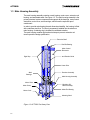
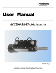
ACT2000
Operations
Manual
ACT2000
All-Electric Actuator
SD-6008-03
This manual provides installation, maintenance, and operating instructions for the
ACT2000 All-Electric Actuator.
Every attempt has been made to provide sufficient information in this
manual for the proper operation and preventive maintenance of the
actuator. It is recommended that the user read this manual in its entirety.
Operating the ACT2000 All-Electric Actuator in accordance with instructions
herein ensures long term and reliable operation.
If additional information is required, please contact:
Marketing Department
Precision Engine Controls Corporation
11661 Sorrento Valley Road
San Diego, California 92121
(858) 792-3217 • (800) 200-4404
fax: (858) 792-3200
e-mail: [email protected]
© 2000 PRECISION ENGINE CONTROLS CORPORATION. ALL RIGHTS RESERVED
ACT2000
II
ACT2000
Table of Contents
Table of Contents ........................................................................................................................................ i
1 INTRODUCTION............................................................................................................................. 1-1
1.1 Application .................................................................................................................................... 1-1
1.2 Mounting Provisions..................................................................................................................... 1-1
1.3 Main Housing Assembly .............................................................................................................. 1-2
1.4 Brushless DC Motor Assembly....................................................................................................1-3
1.5 Motor Control Electronics............................................................................................................. 1-3
1.6 Resolver Assembly ...................................................................................................................... 1-3
1.7 Linear Drive Mechanism .............................................................................................................. 1-4
1.8 Power and Digital Harness .......................................................................................................... 1-4
1.9 Identification Plate ........................................................................................................................ 1-5
2 FUNCTIONAL DESCRIPTION AND OPERATION....................................................................... 2-1
2.1 System Description ...................................................................................................................... 2-1
2.2 Electronic Description .................................................................................................................. 2-1
2.3 Basic Operation and State Description ....................................................................................... 2-6
2.4 Health Monitoring ......................................................................................................................... 2-8
2.5 FAULT Alarm................................................................................................................................ 2-9
2.6 OVERTEMP Alarm ....................................................................................................................2-10
2.7 Automatic Shutdown ..................................................................................................................2-10
2.8 ACT2000 Set-Up Parameters ...................................................................................................2-11
3 INSTALLATION ............................................................................................................................... 3-1
3.1 Inspection...................................................................................................................................... 3-1
3.2 Environmental Considerations..................................................................................................... 3-1
3.3 Mechanical Installation................................................................................................................. 3-1
3.4 Electrical Installation..................................................................................................................... 3-4
4 TROUBLESHOOTING.................................................................................................................... 4-1
5 DECOMMISSIONING AND DISPOSAL ........................................................................................ 5-1
6 ACT2000 GENERAL SPECIFICATIONS....................................................................................... 6-1
7 GLOSSARY..................................................................................................................................... 7-1
I
ACT2000
List of Figures
Figure 1-1: ACT2000 Pin Mounted....................................................................................1-1
Figure 1-2: ACT2000 Flange Mounted..............................................................................1-1
Figure 1-3: ACT2000 Cut-Away View ...............................................................................1-2
Figure 1-4: Typical Identification Plate...............................................................................1-5
Figure 2-2: Typical Power Connection ..............................................................................2-3
Figure 2-3: Typical Discrete Command Connection.........................................................2-3
Figure 2-4: Typical Analog Input Connection ....................................................................2-4
Figure 2-5: Typical Analog Output Connection .................................................................2-4
Figure 2-6: Typical Fault Alarm Connection......................................................................2-5
Figure 2-7: ACT2000 State Machine.................................................................................2-7
Figure 3-1: ACT2000-590P Envelope ...............................................................................3-2
Figure 3-2: ACT2000-200F Envelope ...............................................................................3-3
Figure 3-3: ACT2000 Wiring Diagram ...............................................................................3-8
List of Tables
Table 2-1: ACT2000 Setup Parameters..........................................................................2-12
Table 3-1: Power Harness Recommended Wire Size......................................................3-5
Table 3-2: Digital Harness Recommended Wire Size ......................................................3-6
Table 3-3: ACT2000 Power Harness Wire List.................................................................3-7
Table 3-4: ACT2000 Digital Harness Wire List .................................................................3-9
Table 3-5: Power Supply Requirements..........................................................................3-10
Table 4-1: ACT2000 Initial Installation Troubleshooting Chart.........................................4-2
Table 4-2: ACT2000 In-Service Troubleshooting Chart ...................................................4-3
Table 4-3: ACT2000 Electrical Hook-Up Continuity Troubleshooting Chart.….…...4-3
II
ACT2000
1 INTRODUCTION
This publication covers operation, installation and maintenance instructions for
the ACT2000 Actuators manufactured by Precision Engine Controls Corporation.
1.1 Application
The ACT2000 All-Electric Actuator is designed to meet general industrial motion
control requirements for high temperature hazardous locations. Typical
applications include gas turbine guide vane and valve motion control.
1.2 Mounting Provisions
The ACT2000 can be pin or flange mounted. Figure 1-1 shows a pin-mounted
actuator. Figure 1-2 shows a flange-mounted actuator. Other configurations can
be provided. Please consult Precision Engine Controls Corporation.
Figure 1-1 ACT2000-590P Pin Mounted
Figure 1-2 ACT2000-200F Flange Mounted
The pin-mounted ACT2000 configuration includes a stainless steel machined
clevis. The clevis is fully rotational to allow variable angular indexing as required
for installation. The extension rod provides a female thread for user supplied end
attachments. A spherical rod end bearing attachment is preferred.
The ACT2000 contains a brushless direct current (DC) motor-driven linear
actuator with on-board digital motor control electronics. The primary actuator
components are described in the balance of this section.
1-1
ACT2000
1.3 Main Housing Assembly
The main housing assembly contains a main housing, motor cover, extension rod
bearing, and associated seals. See Figure 1-3. The main housing assembly is the
primary structural system component and supports all the bearings, motor control
electronics, motor cover, and mountings, which forms the explosion-proof
containment.
In order to provide main bearing thermal dimensional stability, the housing is fitted
with a stainless steel liner. The liner is permanently installed into the aluminum
main housing. A retaining ring is included for redundant retention.
The main housing contains rigid mechanical stops to prevent extension rod
travel beyond the design specification.
Extension Shaft
Rod End Bearing
Motor Control
Electronics
Rigid Stop
Anti Rotation Guide
Linear Drive
Main
Bearings
Resolver Assembly
Main Housing Assembly
Motor Rotor
Motor Stator
Brushless DC
Motor Assembly
Motor End Bearing
Motor Cover
Mounting Clevis
Figure 1-3 ACT2000 Cut-Away View
1-2
ACT2000
1.4 Brushless DC Motor Assembly
A brushless DC motor powers the ACT2000 linear drive mechanism. The DC
motor contains a stator and rotor. See Figure 1-3
Motor Stator
The motor stator is attached to the main housing by a pre-loaded wave spring
and screws. Thermistors are embedded in the stator windings to monitor winding
temperatures. The motor electrical power and thermistor wires pass from the
motor through a conduit into the electronics housing.
Motor Rotor
The motor rotor is locked to the ball screw shaft via a straight key. The motor rotor
contains powerful magnets that align with the energized stator windings thereby
creating torque and shaft rotation.
1.5 Motor Control Electronics
The motor control electronics (MCE) are contained within the main housing
electronics enclosure. The MCE includes harnesses, heat sink, digital and driver
component assemblies (CA).
The MCE electronics communicate with the user’s controller through analog and
serial interfaces. The MCE controls the brushless DC motor, to position the
actuator based on position feedback from the resolver.
Note: The digital board analog and discrete interfaces are electrically
isolated. The MCE serial interface is NOT electrically isolated.
1.6 Resolver Assembly
A Brushless, non-contacting resolver is the primary ACT2000 feedback sensor.
A sinusoidal feedback signal is provided from the resolver to the motor control
electronics. A sinusoidal signal from the MCE provides the resolver excitation.
The resolver includes a stator and rotor. See Figure 1-3
Resolver Stator
The resolver stator is clamped to the main housing between the main bearing
retaining nut and resolver retainer. The resolver stator angular position relative to
the rotor is adjustable. Electrical wires from the resolver are reeled in the resolver
adapter to allow rotation. The resolver wires, along with the motor and thermistor
leads, are routed through a conduit into the electronics housing.
Resolver Rotor
The resolver rotor is mounted by a key to a ball screw shaft. As the rotor rotates,
the stator transformer output signal provides shaft rotation information to the
MCE.
1-3
ACT2000
1.7 Linear Drive Mechanism
The Linear Drive Mechanism converts the rotary motion of the Motor Assembly to
linear actuator motion. The core of the mechanical drive system is the linear ball
screw drive containing a screw shaft, ball bearing fitted nut, extension rod and
main duplex thrust bearings.
Screw Shaft
The thrust bearings, motor rotor, motor end bearing, and resolver rotor are
mounted directly to the screw shaft. A ball bearing track is machined into the
screw shaft.
Ball Nut
As the screw shaft rotates, the ball nut translates in an axial direction depending
on shaft rotation.
Extension Rod and Bearings
The extension rod is threaded on the ball nut. As the ball nut translates, the
extension rod moves in and out of the ACT2000 main housing.
The extension rod support bearing is provided for lateral support. Thrust and
radial loads are transferred from the extension rod through the ball nut to the main
preloaded duplex thrust bearings. The thrust bearings transfer the loads to the
main housing by the main bearing and shaft retaining nuts.
A motor end bearing is provided for additional shaft radial stability. The resolver
rotor, motor rotor, motor bearing, and spacers are stacked on the ball screw shaft
and retained by a single nut. This arrangement prevents actuator axial loads from
passing through the resolver rotor and motor rotor.
1.8 Power and Digital Harness
A four-wire electrical harness with two (2) meter free leads provides the ACT2000
electrical power inputs. The four-wire harness allows for redundant electrical
inputs.
A seventeen-wire electrical harness with ninety (90) inch free leads provides
ACT2000 signal interface. Contained within this seventeen-wire harness are
discrete commands, analog commands, feedback, and serial interface wires.
1-4
ACT2000
1.9 Identification Plate
A product identification plate is attached to the
actuator housing assembly. Figure 1-4 shows a
typical identification plate.
The identification plate lists model designation,
product part number, revision and unit serial
number. Hazardous area operation, certification
and electrical wiring interface information is also
provided.
Figure 1-4: Typical Identification Plate
1-5
ACT2000
INTENTIONALLY BLANK
1-6
ACT2000
2 FUNCTIONAL DESCRIPTION AND OPERATION
This section describes system functions employed in the ACT2000
Electric Actuator.
2.1 System Description
The ACT2000 is a closed loop servo system containing motor control electronics
(MCE) and a brushless DC motor driven ball screw actuator. The actuator closes
its own control loop on an internally generated position feedback. Thus, the
actuator continuously modulates its position and provides precise positioning.
The ACT2000 requires only 120VDC power, 4-20 mA position demand, and
discrete RUN command to achieve basic operational capability. The ACT2000
provides position and motor current feedback via integral 4-20 mA circuits. Once
120VDC power and RUN command are supplied, the actuator will track position
demand.
2.2 Electronic Description
The ACT2000 electric actuator incorporates digital motor control electronics. The
electronic system block diagram is shown in Figure 2-1. Contained within the
motor control electronics (MCE) are digital and driver CA. The digital and driver
component assemblies contain analog to digital converters, digital signal
processor (DSP), application specific integrated circuit (ASIC) and power
supplies.
Digital CA
The digital CA interfaces with a user-provided control system that is typically a
programmable logic controller (PLC). The digital CA accepts analog position and
discrete RUN and RESET commands from the control system. The digital CA
provides analog position and motor current feedback to the control system. In
addition, the digital CA provides discrete FAULT and OVERTEMP alarms to the
control system.
The digital CA receives position feedback from the resolver and current feedback
from the driver CA. The digital CA can provide speed, temperature, voltage and
other relevant information through the serial interface using ActWiz software.
Contact Precision Engine Controls for ActWiz software.
Note: The digital board analog and discrete interfaces are electrically
isolated. The RS232C serial interface is NOT electrically isolated.
Driver CA
The driver CA interfaces with the user’s power supply; typically a 120 VDC
battery. The driver CA controls current to the brushless DC motor and provides
precise voltage and current inputs to the digital CA.
2-1
ACT2000
DRIVER ASSY
120V
ACTUATOR +
POWER
(80 - 160 VDC) -
RED
WHITE/RED
GREEN
WHITE/GREEN
REVERSE
POLARITY
PROTECTION
POWER
ELECTRONICS
BRUSHLESS
DC MOTOR
DEMAND
DEMAND RTN
POSITION
POSITION RTN
MTR CURRENT
MTR CURRENT RTN
RUN
RUN RTN
RESET
RESET RTN
FAULT ALARM
FAULT RTN
OVERTEMP ALARM
OVERTEMP RTN
SERIAL TX OUT
SERIAL RX IN
SERIAL RTN
BROWN
WHITE/BROWN
INPUT
TERMINATION
YELLOW
WHITE/YELLOW
BLUE
4-20mA
OUTPUT
WHITE/BLUE
VIOLET
OPTICAL ISOLATION
POWER
INTERFACE
BALL SCREW
AND
SHAFT
GRAY
WHITE/GRAY
ORANGE
WHITE/ORANGE
BLACK
WHITE/BLACK
RS-232 DRIVER
CONTROL
INTERFACE
DIGITAL ASSY
ACTUATOR
Figure 2-1: ACT2000 Electronics System Block Diagram
2-2
CONTROL
ELECTRONICS
OPTICAL
ISOLATION
WHITE/VIOLET
WHT/ORN/BLU
WHT/ORN/YEL
WHT/ORN/GRN
RESOLVER
ACT2000
2.2.1
Power
The ACT2000 operates on nominal 120 VDC, user-provided input voltage via the
four-wire power harness. Refer to Figure 2-2 for typical connection. Refer to
section 6 for specification values.
Primary power wires.
•
+120 VDC is connected to the RED wire.
•
The 120 VDC return wire is GREEN.
Redundant power wires:
•
+120 VDC is connected to the WHITE/RED wire.
•
120 VDC return wire is WHITE/GREEN.
ACTUATOR 120V INPUT
BATTERY/POWER SUPPLY
120VDC
PWR
[RED]
PWR AUX [WHT/RED]
FUSE
PWR RTN AUX [WHT/GRN]
PWR RTN
[GRN]
REVERSE VOLTAGE PROTECTION
Figure 2-2: Typical Power Connection
WARNING:
Shock Hazard – Both the 120 VDC power and auxiliary wires should be
connected. If only the primary power wires are connected, the 120 VDC
auxiliary power wires are electrically “hot” and must be insulated on the
ends.
Note: If a 120 VDC power supply is used, it must have at least 50,000 uF
internal capacitance. See Power Supply Requirements (Table 3-5).
2.2.2
Discrete Commands
The ACT2000 accepts two discrete, two-wire external commands: RUN and
RESET. The commands are 24 VDC ON (High) and 0 VDC OFF (Low). Refer to
Figure 2-3 for typical connection. Refer to Section 6 for specification values.
CONTROLLER DISCRETE OUTPUT
24Vdc
ACTUATOR DISCRETE INPUT
RUN
RESET
[VIO]
[GRY]
RUN RTN
RESET RTN
[WHT/VIO]
[WHT/GRY]
CONTROLLER DISCRETE OUTPUT
ACTUATOR DISCRETE INPUT
RUN
RESET
RUN RTN
RESET RTN
[VIO]
[GRY]
[WHT/VIO]
[WHT/GRY]
Figure 2-3: Typical Discrete Command Connection
2-3
ACT2000
Run Command
The RUN command is a user provided discrete input to the ACT2000 which
allows the actuator to track position demand. The +24 VDC signal shall be
provided on the VIOLET wire. The signal return shall be provided on the
WHITE/VIOLET wire.
Reset Command
The RESET command is a user provided discrete input to the ACT2000, which
causes the actuator to go through the initial homing sequence and reset all
internal position indicators. RUN and position demand inputs are ignored during
the RESET command. The +24VDC signal shall be provided on the GRAY wire.
The signal return shall be provided on the WHITE/GRAY wire.
2.2.3
Analog Inputs/Outputs
The ACT2000 receives analog position demand from an external, user-provided
controller and provides analog actuator position and motor current feedback.
Refer to Figures 2-4 and 2-5 for typical connection. Refer to Section 6 for load
specification values.
CONTROLLER 4-20mA OUTPUT
DEMAND [BRN]
+
-
ACTUATOR 4-20mA INPUT
200Ω
DEMAND RTN
+
-
[WHT/BRN]
Figure 2-4: Typical Analog Input Connection
CONTROLLER 4-20mA INPUT
+
-
ACTUATOR 4-20mA OUTPUT
POSITION
MTR CURRENT
500Ω
POSITION RTN
MTR CURRENT RTN
[YEL]
[BLU]
[WHT/YEL]
+
-
[WHT/BLU]
Figure 2-5: Typical Analog Output Connection
Position Demand
The position demand is a 4-20mA user provided analog input that causes the
actuator to a command position. The position demand shall be provided on the
BROWN wire. The position demand return shall be provided on the
WHITE/BROWN wire. The position demand internal impedance is 200 ohms. The
position demand requires a sourcing current.
Position Feedback
The ACT2000 provides actuator analog position feedback to the user. This
internally generated feedback signal is proportional to the actual position.
The actuator position feedback is provided on the YELLOW wire. The actuator
position feedback return is provided on the WHITE/YELLOW wire. The expected
external impedance is 250 ohms. The maximum external impedance is 500
ohms. Typically, the position feedback will be within + 0.1 mA of the position
demand.
2-4
ACT2000
Motor Current Feedback
The ACT2000 provides motor current feedback to the user. This internally
generated feedback signal is proportional to actuator load. 4mA represents no
load on the actuator.
The motor current feedback is provided on the BLUE wire. The motor current
feedback return is provided on the WHITE/BLUE wire. The expected external
impedance is 250 ohms. The maximum external impedance is 500 Ohms.
2.2.4
Fault Alarms
The discrete alarm outputs are opto-isolated electronic switches that are normally
closed. The user controller provides 24 VDC with current limiting resistor, to
complete the circuit. If a FAULT or OVERTEMP alarm has occurred, the switch
opens thereby communicating an alarm to the user’s controller. Refer to Figure 26 for typical connection. Refer to Section 6 for load specification values.
CONTROLLER DISCRETE INPUT
ACTUATOR DISCRETE OUTPUT
CONTROLLER DISCRETE INPUT
FAULT ALARM
OVERTEMP ALARM
[ORN]
[BLK]
FAULT RTN
OVERTEMP RTN
[WHT/ORN]
[WHT/BLK]
ACTUATOR DISCRETE OUTPUT
FAULT RTN
OVERTEMP RTN
[WHT/ORN]
[WHT/BLK]
FAULT ALARM
OVERTEMP ALARM
[ORN]
[BLK]
Figure 2-6: Typical Fault Alarm Connection
The FAULT alarm is provided on the ORANGE wire. The FAULT alarm return is
provided on the WHITE/ORANGE wire.
The OVERTEMP alarm is provided on the BLACK wire. The OVERTEMP alarm
return is provided on the WHITE/BLACK wire.
WARNING:
Property Damage – Connection of 24 VDC power across the actuator
discrete output will cause electrical failure of the output. Series resistance
should be added to the 24 VDC output from the controller to limit the
current to 25mA max.
2.2.5
RS232 Communications
RS232 serial communications is achieved with user-provided connection to the
Serial Rx In, Serial Tx Out and Serial Rtn wires.
•
The Serial RX In wire is WHITE/ORANGE/YELLOW.
•
The Serial Tx Out wire is WHITE/ORANGE/BLUE.
•
The Serial Rtn wire is WHITE/ORANGE/GREEN.
The RS232C type interface is used to communicate with the ACT2000 using
ActWiz software.
2-5
ACT2000
2.3 Basic Operation and State Description
The basic operation of the ACT2000 is described in the following sections. The
Power-Up mode section covers the Power Up/Reset and the Set-Up states. The
Run Mode section covers the Home/Dead Band, Holding Motor Current and the
Run states.
POWER
UP/RESET
SETUP
COMMAND
SETUP
COMPLETE
RUN
COMMAND
RESET
COMMAND
SET-UP
RESET
COMMAND
POSITION DEMAND
<4.1 mA AND
ACTUATOR POSITION
FEED BACK
<4.2 mA
HOME
DEADBAND
RESET
COMMAND
MOTOR CURRENT>MAX
HOMING FORCE AND
ACTUATOR VELOCITY <
0.05 IN/SEC
RUN
POSITION
DEMAND
>4.1 mA
HOLDING
MOTOR
CURRENT
Figure 2-7: ACT2000 State Machine
2.3.1 Power-Up Modes
When 120 VDC is applied to the ACT2000, the on-board DC converter supplies
power to the driver and digital boards. The ACT2000 will operate with voltages
ranging from 80 VDC to 160 VDC.
Power-Up/Reset State
Once the digital signal processor (DSP) receives required voltage, it starts the
firmware program and enters the POWER-UP/RESET state. See Figure 2-7. The
program checks electronics health, clears system registers and retrieves set-up
parameters from the electrically erasable programmable read only memory
(EEPROM).
Once the program is complete with the health check, it waits for either the RUN,
RESET or SET-UP command.
•
2-6
If the ACT2000 receives a SET-UP command from the ActWiz software
(through the RS232 interface), firmware program will transition to the SET-UP
state.
ACT2000
•
If the ACT2000 receives a discrete RUN command, the firmware program will
transition to the HOME DEAD BAND state.
•
If the ACT2000 receives a discrete RESET command, the firmware program
will continuously reset. The actuator will not function and will remain in the
power-up/reset state.
WARNING:
Property Damage Hazard – Always remove RUN command during Set-Up
state. If a RUN command is given during program download, the actuator
will not respond until download is complete.
Set-Up State
The ACT2000 communicates with the user in this state. See Figure 2-7. Contact
Precision Engine Controls for a copy of ActWiz software in order to communicate
with the ACT2000.
In this state, a set-up file can be uploaded or downloaded. A Fault file can also be
uploaded using the ActWiz software. Please see ActWiz software manual for
more information.
The ACT2000 can only enter this state via POWER-UP/RESET. The ACT2000
enters this state via a SET-UP command received via the RS232 interface.
The actuator will leave this state after a file has been uploaded or downloaded.
The ACT2000 will not hold position while in this state.
WARNING:
Property Damage Hazard – The ACT2000 will not hold position when
communicating with ActWiz software. Ensure there is no load on the
extension rod when communicating with the actuator.
Once the ACT2000 has completed the power-up operations, it will wait for a RUN
command. The actuator will not move or hold load until a RUN command is
received.
2.3.2 Run Modes
Upon receipt of RUN command, the ACT2000 firmware program will transition to
one of the run modes listed below.
Note: As a safety feature, the ACT2000 will not move without a RUN
command.
Home/Dead Band State
The HOME/DEAD BAND state is used to find HOME position after a
POWER-UP/RESET. See Figure 2-7. The firmware program will transition to
HOME/DEADBAND upon receipt of RUN command.
While in the HOME/DEAD BAND state, the actuator moves at constant
velocity (homing velocity) and direction (extend or retract) until a mechanical
stop is found.
Note: If RUN command is removed, the actuator will not function.
2-7
ACT2000
When the mechanical stop is found (actuator velocity less 0.05 inches per
second), the MCE will apply the maximum homing force. Once the maximum
homing force is applied, the firmware program will transition to the HOLDING
MOTOR CURRENT state.
Holding Motor Current State
In the HOLDING MOTOR CURRENT state, the MCE applies a constant
HOLDING FORCE, as long as, the position demand is > 2mA and < 4.1mA.
See Figure 2-7. This feature allows the HOME position to thermally expand or
contract without damaging the ACT2000.
If the actuator firmware program entered the HOME/DEAD BAND state from
POWER-UP/RESET, the firmware program will immediately define the current
actuator position as HOME (zero).
The actuator firmware program will also enter this state from RUN if the
position demand is < 4.1mA and position feedback is < 4.2mA.
Note: If RUN command is removed or position demand ≤ 2 mA, the
actuator will go to the STOP position.
Run State
The RUN state is the ACT2000 normal operating mode. See Figure 2-7. In
the RUN state, the actuator tracks position demand and will apply up to the
maximum force to reach the demand position.
The actuator firmware program enters this state from the HOLDING MOTOR
CURRENT state if the position demand is ≥ 4.1mA. The actuator firmware
program will remain in this state as long as the demand is greater than
4.1mA.
Note: If RUN command is removed or position demand ≤ 2 mA, the
actuator will go to the STOP position.
Stop Position
The STOP position is a user defined, fail-safe position. The STOP position is a
set-up parameter stored in the EEPROM. The STOP position may be anywhere
between HOME (zero position) and maximum span.
The STOP position is not a state per se. However, while in the STOP position the
ACT2000 firmware program will track and hold the position defined in the Set-Up
parameters.
The actuator will move to the STOP position if RUN command is removed during
any of the running modes or position demand is ≤ 2 mA (signal loss).
2.4 Health Monitoring
The firmware program continuously monitors system health while the ACT2000 is
powered.
2-8
ACT2000
If any of the health parameters are out of the normal operating range, the MCE
outputs a discrete FAULT alarm to the user’s controller. The actuator firmware
also captures the fault data in the EEPROM.
If the motor or electronics temperature is above the normal operation range, the
MCE outputs a separate OVERTEMP alarm. The actuator firmware also captures
the fault data in the EEPROM.
If any of these faults have occurred, the user should shut down the ACT2000 to
investigate the failure cause
If the ACT2000 is operational, a fault file can be uploaded using ActWiz software
via the RS232 interface. The fault file will provide fault information and possible
cause.
2.5 FAULT Alarm
The FAULT alarm is a discrete output from the ACT2000. The FAULT circuit is
CLOSED in the normal operating condition.
During normal operation, the ACT2000 monitors system health. If the ACT2000
detects a fault, the FAULT circuit OPENS and fault records in the fault file. The
user-provided controller should detect the OPEN circuit.
Should a FAULT occur, the user should shut down to troubleshoot the failure.
Removing 120 VDC power shuts down the ACT2000. Toggling the RESET
command will clear the FAULT alarm, but it does NOT clear the fault file.
The following faults are recorded:
Driver over-current
The maximum MCE current output limit is 25 amps. If the MCE is outputting its
maximum current for ten (10) seconds, the MCE signals a FAULT.
Should MCE maximum current drop below the maximum current, the FAULT
signal is cleared.
Tracking error
The ACT2000 position should continuously track demand. Should the position
versus demand vary more than one motor revolution (0.20 inches) for more
than ten (10) seconds, the MCE signals a FAULT.
Should the position return to within one motor revolution, the FAULT signal is
cleared.
Watchdog expired
The MCE watchdog timer continuously monitors the firmware program. Should
the MCE firmware program stop functioning, or attempt to access an illegal
address, the MCE signals a FAULT.
This FAULT does not clear without RESET command.
Resolver to Digital Converter (RDC) failure
The MCE contains a resolver to digital converter chip (RDC) that provides
position feedback information to the DSP. The RDC chip has on-board health
monitoring.
Should the RDC detect an internal tracking error, a signal is sent to the MCE.
Upon receipt, the MCE signals a FAULT.
2-9
ACT2000
This FAULT does not clear without RESET command.
Unregulated Voltage Low
The MCE signals a FAULT if the reference voltage drops below minimum for
ten (10) seconds.
Should the voltage return to acceptable level, the FAULT signal is cleared.
+/- 14V High/Low
The MCE signals a FAULT if the internal ±14 VDC power supplies exceed
operating limits. This FAULT does not clear without RESET command.
Input voltage High/Low
The MCE signals a FAULT if the 120 VDC supply exceeds 180 VDC or drops
below 75 VDC for more than 10 seconds. This FAULT clears when the 120 VDC
supply voltage returns.
2.6 OVERTEMP Alarm
The OVERTEMP alarm is a discrete output from the ACT2000. The OVERTEMP
circuit is CLOSED in the normal operating condition.
During normal operation, the ACT2000 monitors the electronics and motor
winding temperatures. If ACT2000 detects the motor or electronics temperature
above the maximum allowable, the OVERTEMP circuit is opened. The userprovided controller should detect the open circuit.
An OVERTEMP Alarm will be indicated if the motor winding temperature is 130°C
or higher for ten (10) seconds or the electronics temperature is 110°C or higher
for ten (10) seconds.
Should an OVERTEMP alarm occur, the user should shut down the actuator.
Removing 120 VDC power shuts down the ACT2000. Toggling the RESET
command will clear the FAULT alarm, but it does NOT clear the fault file.
Note: The ACT2000 outputs an OVERTEMP alarm 5°C before the shut
down threshold.
2.7 Automatic Shutdown
The ACT2000 has a self-protective shutdown feature.
•
If any two motor winding temperatures exceed 135 °C for one (1) minute, the
ACT2000 will shut down.
•
If the electronics temperature exceeds 115 °C for one (1) minute, the
ACT2000 will shut down.
Note: Actuator position feedback and motor current will be set to 0 mA
when the actuator shuts down.
WARNING:
Property Damage and Injury Hazard – If the motor windings exceed 135° C
or the electronics exceed 115° C, the MCE will shut down power to the
motor and electronics thereby allowing the actuator to move with load.
Touching actuator may result in serious burn injury
2-10
ACT2000
2.8 ACT2000 Set-Up Parameters
The ACT2000 employs several variables to define its functionality. These
variables are called set-up parameters. These parameters are downloaded
through the RS232 interface to the ACT2000 using ActWiz software. See ActWiz
Software Manual for further details.
The user can define set up any of the following parameters:
Home (Extend or Retract)
This parameter controls the direction the ACT2000 will move, extend or retract, to
find the mechanical stop (HOME).
Span
This parameter sets the maximum stroke length. The span is measured from the
HOME position.
Stop Position
This parameter sets the signal loss position. The signal loss position is measured
from the HOME position.
Maximum Velocity
This parameter sets the maximum velocity.
Maximum Force
This parameter sets the maximum force output.
Maximum Homing Velocity
This parameter sets the maximum velocity used to find the HOME position.
Maximum Homing Force
This parameter sets the maximum force the ACT2000 will use to find the HOME
position.
Maximum Holding Force
This parameter sets the maximum force at the HOME position while the position
demand is < 4.1mA.
2-11
ACT2000
Table 2-1 lists the set-up parameters and factory default settings.
Parameter
Part Number
Factory Setting
Per Drawing
Actuator Type
Stand Alone
Command Source
Analog
Home
Retract
Span
5.9 inches
Stop Position
0.1 inches
Interpolation Table
Linear
Position Loop Constant
20
Current Loop PID Constants
Proportional
2.0
Integral
200
Derivative
0
Velocity Loop PID Constants
Proportional
40
Integral
10,000
Derivative
0
Maximum Velocity
6 in/s
Maximum Force
1000 lbf
Maximum Homing Velocity
0.5 in/s
Maximum Homing Force
500 lbf
Maximum Holding Force
500 lbf
Table 2-1 Typical ACT2000 Setup Parameters
2-12
ACT2000
3 INSTALLATION
The purpose of this section is to aid personnel in the installation, placement, and
environmental considerations to be observed for the ACT2000 and associated
equipment.
3.1 Inspection
The ACT2000 should be inspected immediately after unpacking. Check for
damage, paying particular attention to the external lead wires.
Note: Retain the actuator’s original shipping container. In the event of
future transportation requirements, this container will minimize
damage during shipment.
3.2 Environmental Considerations
The ACT2000 will operate satisfactorily with ambient air temperature of -40 °C
(-40 °F) to +93 °C (+200 °F). The ACT2000 is designed as an explosion-proof
assembly. The ACT2000 enclosure is Canadian Standards Association (CSA)
Type 3.
WARNING: Property Damage – Solvent/water may enter the electronics
area during a high-pressure wash.
3.3 Mechanical Installation
This section describes proper ACT2000 installation. Care should be exercised to
ensure compliance with the factory recommendations.
3.3.1
Space Requirements
Figure 3-1 shows external dimensions and mounting provisions for the ACT2000590P. Figure 3-2 shows the external dimensions and mounting provisions for the
ACT2000-200F. The user should ensure additional swing clearance as required.
3.3.2
Mounting Considerations
The ACT2000 can be directly mounted to a gas turbine engine using brackets
provided by the engine manufacturer. The ACT2000 can be mounted in any
orientation (UP, DOWN, SIDEWAYS).
The ACT2000 may provide a clevis, or other method, for installing the motor end.
High strength bolts (0.375 diameter) are recommended to secure the actuator to
a user-provided mount bracket.
WARNING:
Lifting Hazard – Do not attempt to hand lift actuator. Use appropriate lifting
equipment.
3-1
ACT2000
Figure 3-1: ACT2000-590P Envelope
3-2
ACT2000
Figure 3-2: ACT2000-200F Envelope
3-3
ACT2000
Note: The clevis can be rotated to any orientation to support installation.
To rotate, loosen the four retaining screws and rotate to desired
angle. Screw pattern can be indexed ± 45 degrees to provide
additional adjustment. Torque the four retaining screws to
117-138 in-lbs.
WARNING:
Explosion Hazard – Do not remove the clevis. Removing the clevis violates
the warranty.
The extension rod has a 0.375-24 UNF-3B female thread for user-provided
hardware. The user may provide a standard 0.375-24-3B rod end
(recommended) or other appropriate mounting hardware. The extension rod has
wrench flats to counteract mounting hardware installation torque.
WARNING:
Property Damage Hazard – Always use the extension rod wrench flats
when installing mounting hardware. Failure to use the wrench flats may
damage or break the internal anti-rotation guide.
3.3.3
Extension Rod Movement
With 120 VDC power removed, the ACT2000 extension rod is free to move.
Approximately 60 to 100 lbf is required to extend or retract the extension rod. A
rod guide is provided internally to prevent extension rod rotation.
WARNING:
Property Damage Hazard – Do not attempt to rotate the extension rod. This
may damage the internal anti-rotation guide and void the warranty.
3.4 Electrical Installation
The ACT2000 is suitable for use in hazardous locations. See nameplate
for certifications. Care should be taken to ensure compliance with the factory
recommendations. Wiring must be in accordance will local authorities jurisdiction.
3.4.1
Wiring Specifications and Requirements
This section describes the recommended power and control harness wiring to the
ACT2000. Please consult the factory if there are any questions. See Table 3-5 for
DC power supply requirements.
3-4
ACT2000
WARNING:
94/9/EC (ATEX) Compliance – Special Conditions for Safe Use:
Two special factory-sealed unions are mounted on the equipment to ensure
the electrical connection to the network and to provide the feedback signal
to the user.
The installation of these devices and the final connections to the conduit
shall comply with the requirements of the European standards.
Power Harness Recommended Wiring
Under normal operation and load, the ACT2000 requires less than one (1) amp
input current.
Under transient operation (under load) the ACT2000 may require up to (20) amps
of current.
The recommended wiring is a two-conductor shielded cable containing twistedpair wires with individual shields. Use a wire size large enough to accommodate
the installation and provide a maximum one (1) ohm loop resistance. See Table
3-1 (below) for recommended wire sizes.
Distance to User Power
Up to 500 ft
Over 500 ft
Wire Size (Minimum)
AWG 10 stranded
Consult Factory
Table 3-1: Power Harness Recommended Wire Size
WARNING:
Shock Hazard – Both the 120 VDC power and auxiliary wires should be
connected. If only the primary power wires are connected, the 120 VDC
auxiliary power wires are electrically “hot” and must be insulated on the
ends.
Note: Use a separate conduit for the power wiring. This will prevent noise
pickup and transmission from ancillary equipment, which could
cause instability in the actuator.
Signal Harness Recommended Wiring
The signal harness contains both analog and digital inputs and outputs. The
analog inputs and outputs are 4mA to 20mA and are electrically isolated up to
500 VAC from the enclosure, 120VDC power, digital I/O, and serial interface. The
analog interfaces are not isolated from each other.
3-5
ACT2000
Note: For proper operation of the actuator, the voltage between the control
inputs and the negative terminal of the power supply should be below 200 VDC.
The discrete inputs and outputs are 24 VDC and are electrically isolated up to
500 VAC.
The recommended wiring is a fourteen-conductor shielded cable containing
twisted-pair wires with individual shields. Use a wire size large enough to
accommodate the installation and provide a maximum fifty (50) ohm loop
resistance. See Table 3-2 for recommended wire sizes.
Distance to User Controller
Up to 1000 ft
Over 1000 ft
Wire Size (Minimum)
AWG 18 stranded
Consult Factory
Table 3-2: Digital Harness Recommended Wire Size
Note: Use a separate conduit for the signal wiring. This will prevent noise
pickup and transmission from ancillary equipment, which could
cause instability in the actuator.
Shielded Wiring
All shielded cable must be a twisted conductor pair with either a foil or braided
shield. All signal lines should be shielded to prevent picking up stray signals.
Connect shields per Figure 3-3 (page 3-8). Wire exposed beyond the shield
should be as short as possible.
WARNING:
Property Damage Hazard – This actuator is 89/339/EEC EMC Directive
compliant (CE mark) using watertight, flexible conduit (plastic over steel)
and Belden 8719 shielded, twisted pair audio, broadcast and
instrumentation cable. Use of other conduit or wire invalidates EMC
Directive compliance.
Property Damage Hazard – Do Not connect 24VDC power without current
limiting (25 mA) across digital or analog outputs.
Serial Wiring
The serial inputs are not electrically isolated. Isolation must be provided when
connecting to a computer.
3-6
ACT2000
WARNING:
Property Damage Hazard – Serial inputs are not electrically isolated. Failure
to properly isolate the user serial interface could result in actuator or
computer damage. Use separate conduits for power and signal wiring.
Close proximity to power lines may cause signal interference.
Shock Hazard – The serial inputs are not electrically isolated. If the 120 VDC
power input is floating (not grounded), the serial input connections may
have up to 120 VDC present.
Property Damage Hazard – DO NOT connect 24VDC power to any of the
serial interface connections.
Note: Serial connection limited to 50 ft for local interface only with laptop PC.
3.4.2
Wire Lists
This section will provide ACT2000 wire hook-up information.
Power Harness Electrical Hook-Up
Table 3-3 shows the factory wiring for the ACT2000 power harness.
Wire Color
RED
WHITE/RED
GREEN
WHITE/GREEN
Function
Power
Power (AUX)
Power Return
Power Return (AUX)
AWG
14
14
14
14
Table 3-3: ACT2000 Power Harness Wire List
3-7
ACT2000
Power Harness Electrical Hook-Up
POWER SUPPLY
+120VDC
-120VDC Return
Power Gnd Shield
ACT2000
PWR (RED)
PWR [AUX] (WHT/RED)
PWR RTN (GRN)
PWR RTN [AUX] (WHT/GRN)
Shield No Connection
Digital Harness Electrical Hook-Up
Demand
Return
Shield Gnd
DEMAND (BRN)
DEMAND RTN (WHT/BRN)
Shield No Connection
Run
Return
Shield Gnd
RUN (VIO)
RUN RTN (WHT/VIO)
Shield No Connection
Reset
Return
Shield Gnd
RESET (GRY)
RESET RTN (WHT/GRY)
Shield No Connection
Motor Current
Motor Current RTN
Shield Gnd
Position
Position RTN
Shield Gnd
Fault Alarm
Fault Alarm
Shield Gnd
Over Temp Alarm
Over Temp Alarm
Shield Gnd
Shield Gnd
Serial RX in
Serial TX out
Serial RTN
Shield Gnd
ENGINE CONTROLLER
Figure 3-3: ACT2000 Wiring Diagram
3-8
MTR CURRENT (BLU)
MTR CURRENT RTN(WHT/BLU)
Shield No Connection
POSITION (YEL)
POSITION RTN(WHT/YEL)
Shield No Connection
FAULT ALARM (ORN)
FAULT RTN (WHT ORN)
Shield No Connection
OVERTEMP ALARM (BLK)
OVERTEMP RTN (WHT/BLK)
Shield No Connection
Shield No Connection
SERIAL TX OUT (WHT/ORN/BLU)
SERIAL RX IN (WHT/ORN/YEL)
SERIAL RTN (WHT/ORN/GRN)
Shield No Connection
ACT2000
ACT2000
Table 3-4 shows the factory wiring and reference signals for the ACT2000 signal
harness.
Note: The serial wiring is segregated from the other wires.
Wire Color
WHITE/ORANGE/YELLOW
Function
Serial/RX In
AWG
20
WHITE/ORANGE/BLUE
Serial/TX Out
20
WHITE/ORANGE/GREEN
BLACK
WHITE/BLACK
ORANGE
WHITE/ORANGE
VIOLET
WHITE/VIOLET
GRAY
WHITE/GRAY
BROWN
WHITE/BROWN
YELLOW
WHITE/YELLOW
BLUE
WHITE/BLUE
Serial Return
OVER TEMP Alarm
OVER TEMP Alarm Return
FAULT Alarm
FAULT Alarm Return
RUN Command
RUN Command Return
RESET Command
RESET Command Return
Position Demand
Position Demand Return
Position Feedback
Position Feedback RTN
Motor Current
Motor Current RTN
20
20
20
20
20
20
20
20
20
20
20
20
20
20
20
Signals
± 12 V
± 12 V
0V
0 / 24 V
0V
0 / 24 V
0V
0 / 24 V
0V
0 / 24 V
0V
4 – 20mA
0V
4 – 20mA
0V
4 – 20mA
0V
Note: The serial Return is connected to the 120 V input return.
Table 3-4: ACT2000 Digital Harness Wire List
3-9
ACT2000
Power Supply Requirements
A battery power system is recommended, Table 3-5 lists the power supply
requirements.
Voltage:
Max Ripple:
120VDC nominal
80VDC minimum
160VDC maximum
4 VAC RMS or 12VAC p-p
Max Current:
Typical Continuous Current:
Typical Transient Current:
20 AMPS
<1 AMP
+20 A <60ms
+10A <600 ms
-5A <100 ms
*Output Capacitance:
50,000 uF
*The output capacitance applies for non-battery power systems and assumes full stroke step changes in actuator
position at rated load.
Table 3-5 Power Supply Requirements
3-10
ACT2000
4 TROUBLESHOOTING
The information contained in this section is intended to aid maintenance
technicians in troubleshooting and isolating causes of malfunctions in the
ACT2000. Most electrical fault isolation of the actuator can be accomplished by
using an external oscilloscope and digital voltmeter (DVM).
The ACT2000 is comprised of highly reliable components and should not develop
service problems under normal operating conditions. However, over a period of
time and service, failures may develop. Personnel responsible for fault analysis
should be thoroughly acquainted with physical and electrical configurations,
Theory of Operation (Section 2), and Installation (Section 3).
Resolve problems noted during operation or maintenance as soon as possible.
The causes of many problems can be traced through the information contained in
the block diagrams shown in Section 2.
WARNING:
Property Damage Hazard – Continuing to operate the actuator in a
malfunctioning condition is hazardous to personnel and can cause
property damage.
Table 4-1 lists some common failures that can occur upon initial actuator
installation. Table 4-2 lists some common failures that can occur after initial
installation.
In addition, the ACT2000 has some on-board troubleshooting capability. The
ActWiz software has a fault file that can be uploaded to pinpoint a failure cause.
See ActWiz Software Manual for more details.
If, after following the troubleshooting procedures, the user is unable to find the
cause of the problem and repair it, contact the factory for assistance. See Section
8 for return information.
4-1
ACT2000
Table 4-1 ACT2000 Initial Installation Troubleshooting Chart
Symptom
Probable Causes
Corrective Action
Actuator Inoperative - FAULT
alarm
Power Wires not connected
Ensure RED and GREEN wires correctly connected to
Actuator
Ensure 120 VDC Primary System Power at Actuator
No or low 120 VDC power
Actuator Inoperative NO FAULT alarm
No RUN or position command
Ensure VIOLET and WHITE/VIOLET wires correctly
connected to Actuator
Ensure 24 VDC RUN and position command at
Actuator
Actuator moves toward
HOME then stops
Intermittent RUN command
Ensure consistent 24 VDC RUN and position command
Ensure position command at actuator
Homing Force Too Low
No position demand
Actuator moves toward
HOME intermittently
Intermittent RESET command
Ensure GRAY and WHITE/GRAY wires correctly
connected to Actuator
Ensure consistent 24 VDC RESET command
Actuator finds HOME then
moves to STOP position
No position demand signal
Ensure BROWN and WHITE/BROWN wires correctly
connected to Actuator
Ensure position demand > 2.0 mA at Actuator
Actuator does not track
position demand
No position demand signal
Ensure BROWN and WHITE/BROWN wires correctly
connected to Actuator
Ensure position demand > 4.1 mA at Actuator
Actuator does not hold
consistent position-oscillates
or dithers
Varying position demand signal
Ensure stable position demand at the actuator
No position feedback
Position feedback wires not
connected
No or low 120 VDC power
Actuator auto shut down
Ensure YELLOW and WHITE/YELLOW wires correctly
connected
Ensure 120VDC at Actuator
Upload Fault File- check for electronics or motor
windings over temperature faults.
Check for jammed extension rod
No motor current feedback
Motor current wires not
connected
No or low 120 VDC power
Ensure BLUE and WHITE/BLUE wires correctly
connected
Actuator Operative- FAULT
alarm active
Open circuit
Ensure ORANGE and WHITE/ORANGE wires
correctly connected to Actuator
Upload Fault File to identify source of fault
Internal FAULT
Actuator Operative- OVER
TEMP alarm active
Open circuit
Electronics or Motor winding
temperature out of range
RS232 Interface Inoperative
Incorrect wiring
No or low 120 VDC power
COM1 not connected
4-2
Ensure BLACK and WHITE/BLACK wires correctly
connected to Actuator
Reduce External ambient temperature
Check for jammed extension rod
Ensure WHITE/ORANGE/YELLOW,
WHITE/ORANGE/BLUE, WHITE/ORANGE/GREEN
wires correctly connected to Actuator and laptop PC.
Ensure 120 VDC Primary System Power at Actuator
Check laptop/PC com port
ACT2000
Table 4-2 ACT2000 In-Service Troubleshooting Chart
Symptom
Probable Causes
Corrective Action
FAULT alarm
Various
Upload Fault File to identify source of fault
OVER TEMP alarm
Ambient temperature limit
exceeded
Allow actuator to cool and re-start
Reduce ambient temperature
Electronics or Motor winding
temperature out of range
Check for jammed extension rod
No 120VDC Power
DSP Failure
Ensure 120 VDC at actuator
Contact factory
FAULT and OVERTEMP
alarm
For troubleshooting purposes use Table 4-3 to verify the actuator electrical continuity integrity.
Disconnect the actuator power and digital harness connectors and use a digital multimeter (DMM)
to check the resistance values between the wires indicated on the table. If an open circuit is
detected, send actuator to Precision Engine Controls Corporation for test and repair.
WARNING:
Shock Hazard – Remove all power to actuator prior to continuity check
Table 4-3 ACT2000 Electrical Hook-Up Continuity Troubleshooting Chart
Function
Actuator Wire Colors
Resistance Value
DEMAND
BRN and WHT/BRN
225Ω
RUN
VIO and WHT/VIO
4.7KΩ
RESET
GRY and WHT/GRY
4.7KΩ
POWER
RED and WHT/RED
High Impedance, but not
open circuit.
MOTOR CURRENT
BLU and WHT/BLU
High Impedance
POSITION
YEL and WHT/YEL
High Impedance
FAULT ALARM
ORN and WHT/ORN
High Impedance
OVERTEMP
BLK and WHT/BLK
High Impedance
4-3
ACT2000
INTENTIONALLY BLANK
4-4
ACT2000
5 DECOMMISSIONING AND DISPOSAL
This section contains recommended ACT2000 decommissioning and disposal
practices. It is for permanent removal or replacement of the installed product, with
no intentions of rework, overhaul, or to be used as spares.
For removal follow proper lockout /tagout procedures and verify no live
electrical circuits:
1.
2.
Disconnect power harness to ACT2000.
Disconnect signal harness to ACT2000
Note: Follow local environmental codes in regards to disposal of electronic
components, specifically all electrolytic capacitors.
5-1
ACT2000
INTENTIONALLY BLANK
5-2
ACT2000
6 ACT2000 GENERAL SPECIFICATIONS
Power Input
Nominal Voltage: 120 VDC
Minimum Voltage: 80 VDC
Maximum Voltage: 160 VDC
Maximum Current: 20A
Typical Transient Current: +20A < 60ms; +10A < 600ms; -5A < 100ms
Typical Continuous Current: < 1A
RUN and RESET Command Input
FAULT and OVERTEMP Output
Analog Command Input
Position and Motor Current Feedback Analog
Maximum Common Mode Voltage
Temperature Limits
Maximum Velocity
Maximum Continuous Force
Maximum Peak Force
Maximum Stroke
Accuracy
Environmental Rating
EMC
Vibration
Mean Time Before Unscheduled Removal
Life Cycles
Electrical Connection
North American Certifications
European Directive Compliance (CE Mark
ON Voltage: 12 to 32 VDC; +24 VDC Nominal
ON Current: 6.5 mA Nominal @ 24 VDC
OFF Voltage: 3.5 VDC Maximum
OFF Current: 0.75 mA Maximum
OFF Voltage: 32 VDC Maximum
OFF Leakage Current: 150 µA Maximum
ON Current: 25 mA Maximum
ON Voltage Drop: 1.5 VDC Maximum @ 25 mA
Current: 4 to 20 mA; 25 mA Maximum
Voltage: 5 VDC Maximum
Internal Impedance: 200 Ω
Current: 4 to 20 mA
External Load Resistance: 500 Ω Maximum
±200 VDC User I/O to 120 VDC Return (less serial interface)
Operating Ambient: -40° C (-40° F) to +93° C (+200° F)
Operating Fuel: -40° C (-40° F) to +125° C (+257° F)
Storage: -40° C (-40° F) to +125° C (+257° F)
10 in/sec
500 lbf (100% Duty Cycle)
1000 lbf (100% Duty Cycle)
5.9 in (Configuration Dependent)
± 1% Full Stroke
CSA Type 3, European IP65
EN 50081-2 and EN50082-2 for DC powered industrial equipment
Mil-Std-810E, Category 4 (5 – 2000 Hz)
30,000 Hours
32,000 Minimum
Power Harness: (4) AWG 14, 90 in, ¾ NPT Conduit (EP)
Digital Harness: (17) AWG 20, 90 in, ¾ NPT Conduit (EP)
CSA Class I, Div 1, Group B, C, D; T4
EEx d, IIB+H2; T4
94/9/EC Potentially Explosive Atmospheres (ATEX)
98/37/EC Machinery Directive
89/336/EEC Electromagnetic Compatibility Directive (EMC)
Materials
Housings
6061-T6 Anodized Aluminum
Conduit Union
Zinc Plated Steel
Extension Rod
17-4 PH CRES
Clevis
17-4 PH CRES
Rod End Bearing
Seals
Dimensions
Approx. Dry Weight
Aluminum Bronze
Nitrile, RTV and Teflon
6.0 in x 16.0 in
Pin Mounted 35 lbs. Max
Flange Mounted 50 lbs. Max
6-1
ACT2000
INTENTIONALLY BLANK
6-2
ACT2000
7 GLOSSARY
Term
Definition
RUN Command
A discrete 24 VDC signal that enables the ACT2000 extension rod to
move.
RESET Command
A discrete 24 VDC signal that causes the ACT2000 internal program
(firmware) to jump to the beginning.
Controller
A user-provided computer that executes commands to the ACT2000
and accepts analog and discrete feedback.
Position Demand
Position Demand Feedback
Motor Current Feedback
FAULT alarm
OVERTEMP alarm
A 4mA to 20mA signal that commands the ACT2000 to move to a
certain position. The signal is scaled with SPAN.
A 4mA to 20mA signal that communicates the actual ACT2000
position to the controller.
A 4mA to 20mA signal that is proportional to the ACT2000 motor
current. The signal is scaled with Max. Force.
A discrete signal from the ACT2000 that communicates an internal
failure. The controller will see an open circuit when a FAULT alarm is
active.
A discrete signal from the ACT2000 that communicates an internal
over temperature; electronics or motor. The controller will see an
open circuit when OVERTEMP alarm is active.
HOME
A mechanical rigid stop at which the ACT2000 calculates position
from. HOME is found at start-up during Homing sequence. The
ACT2000 defines HOME when the motor current exceeds the
HOMING FORCE and velocity is zero. HOME is defined as 4mA
position demand.
Homing sequence
When the ACT2000 extends or retracts to find a rigid mechanical
stop.
SPAN
STOP position
Maximum Velocity
Maximum distance from HOME. SPAN is defined as 20mA position
demand.
A user-defined position between HOME and SPAN that the ACT2000
travels to upon loss of RUN or position demand signal.
A user defined maximum velocity in inches per second.
Maximum Homing Force
A user defined maximum homing force output setting. The motor
control electronics uses this setting to determine the maximum motor
current in the Homing sequence.
Maximum Holding Force
A user defined maximum force while in the Holding Motor Current
state.
7-1
ACT2000
INTENTIONALLY BLANK
7-2
ACT2000
7-1