1
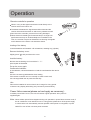
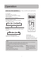
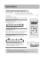
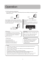
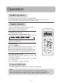
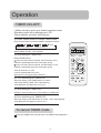
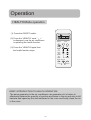
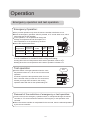
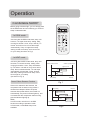
SPLIT TYPE ROOM AIR CONDITIONER
OPERATION MANUAL
HSU-09RF03/R2
HSU-12RF03/R2
Please read this operation manual before using the air conditioner
No.001050
Haier Industrial Park, No.1 Haier Road, Qingdao, P.R.China
IT
CONFORMITÀ ALLE DIRETTIVE EUROPEE PER I MODELLI:
CE
Tutti i prodotti sono conformi alle seguenti normative europee:
- Direttiva 73/23/EEC Basso Voltaggio
- Direttiva 2006/95/EC Basso Voltaggio
- Direttiva 89/336/EEC Compatibilità elettromagnetica
- Direttiva 2004/108/EC Compatibilità elettromagnetica
ROHS
Il prodotto è conforme alla normativa 2002/95/EEC sulla restrizione d’uso di
sostanze inquinanti negli apparecchi elettrici ed elettronici.
WEEE
Informativa al consumatore come previsto dalla normativa europea
2002/96/CE riguardante i rifiuti di apparecchiature elettriche ed elettroniche.
EN
EUROPEAN REGULATIONS CONFORMITY FOR THE MODELS:
CE
All the products are in conformity with the following European provision:
- Low Voltage Directive 73/23/EEC
- Low Voltage Directive 2006/95/EC
- Electromagnetic CompatibilitY 89/336/EEC
- Electromagnetic CompatibilitY 2004/108/EC
ROHS
The products are fulfilled with the requirements in the directive 2002/95/EEC of the
European parliament and of the council on the Restriction of the use of Certain Hazardous Substances in Electrical and Electronic Equipment (EU RoHS Directive).
WEEE
In accordance with the directive 2002/96/CE of the European parliament,
herewith we inform the consumer about the disposal requirements of the
electrical and electronic products.
FR
SPECIFICHE DI SMALTIMENTO:
Il climatizzatore è contrassegnato con questo simbolo,
ciò significa che i prodotti elettrici ed elettronici non
possono essere smaltiti insieme ai rifiuti domestici non
differenziati. Non cercare di demolire il sistema da soli:
la demolizioni dei sistemi di condizionamento, nonché il
recupero del refrigerante, dell’olio e di qualsiasi altra
parte devono essere eseguiti da un installatore qualificato in conformità alla legislazione locale e nazionale
vigente in materia.I climatizzatori devo essere trattati presso una struttura specializzata nel riutilizzo, riciclaggio e recupero dei materiali. Il corretto smaltimento del prodotto eviterà le possibili conseguenze negative all’ambiente e alla
salute dell’uomo. Per maggiori informazioni contattare l’installatore o le autorità locali. Le batterie devono essere tolte dal telecomando e smaltite separatamente conformemente alla legislazione locale e nazionale vigente in materia.
DISPOSAL REQUIREMENTS:
Your air conditioning product is marked with this symbol. This means that electrical and electronic products
shall not be mixed with unsorted household waste.
Do not try to dismantle the system yourself: the dismantling of the air conditioning system, treatment of
the refrigerant, of oil and of other part must be done
by a qualified installer in accordance with relevant
local and national legislation. Air conditioners must be
treated at a specialized treatment facility for re-use, recycling and recovery.
By ensuring this product is disposed of correctly, you will help to prevent
potential negative consequences for the environment and human health.
Please contact the installer or local authority for more information. Battery
must be removed from the remote controller and disposed of separately in
accordance with relevant local and national legislation.
CONFORMITÉ AUX DIRECTIVES EUROPÉENNES POUR LES MODÈLES:
CE
Tous les produits sont conformes aux directives européennes suivantes:
- Directive 73/23/CEE Basse tension
- Directive 2006/95/CE Basse tension
- Directive 89/336/CEE Compatibilité électromagnétique
- Directive 2004/108/CE Compatibilité électromagnétique
ROHS
L'appareil est conforme à la directive 2002/95/CEE relative à la limitation de
l'utilisation de certains substances dangereuses dans les équipements électriques et électroniques.
DEEE (WEEE)
Information au consommateur comme le prévoit la directive européenne
2002/96/CE relative aux déchets d'équipements électriques et électroniques.
SPECIFICATIONS POUR L'ELIMINATION:
Ce pictogramme, apposé sur le climatiseur, signifie
que les équipements électriques et électroniques ne
peuvent pas être éliminés avec les déchets ménagers
non triés. Ne pas essayer de démanteler l'équipement
soi-même: le démantèlement des systèmes de climatisation, ainsi que la récupération du frigorigène, de
l'huile et de toute autre partie doivent être effectués
par un installateur qualifié conformément à la législation locale et nationale en vigueur en la matière. Les climatiseurs doivent être
traités dans un centre spécialisé dans la réutilisation, le recyclage et la valorisation des matériaux. L'élimination correcte de ces appareils permet d'éviter les effets nocifs sur l'environnement et la santé humaine. Pour plus de
renseignements contacter l'installateur ou les autorités locales. Les piles doivent être retirées de la télécommande et éliminées séparément, conformément à la législation locale et nationale en vigueur en la matière.
Haier Industrial Park, No.1 Haier Road, Qingdao, P.R.China
ES
CONFORMIDAD EUROPEA DE LAS REGULACIONES PARA LOS MODELOS:
CE
Todos los productos están en conformidad con las siguientes Normativas
Europeas:
- Bajo Voltaje directiva 73/23/EEC
- Bajo Voltaje directiva 2006/95/EC
- Compatibilidad electromagnética 89/336/EEC
- Compatibilidad electromagnética 2004/108/EC
ROHS
Los productos cumplen los requisitos de la directiva 2002/95/EEC del parlamento Europeo y el consejo regulador Del uso de materiales peligrosos en
equipamientos eléctricos Y electrónicos. (EU RoHS Directiva).
WEEE
De acuerdo con la directiva 2002/96/CE del parlamento Europeo, Informamos al consumidor acerca del reciclage de los productos Electrónicos y
eléctricos.
REQUISITOS PARA LA ELIMINACIÓN:
Su acondicionador de aire está marcado con este
símbolo. Esto significa que los productos eléctricos y
electrónicos no deben mezclarse con el resto de residuos domésticos no clasificados.
No intente desmontar el sistema usted mismo: El desmantelamiento del acondicionador de aire, así como
el tratamiento del refrigerante, aceite y otros componentes, debe ser efectuado por un instalador competente de acuerdo con las normas locales y nacionales aplicables. Los acondicionadores de aire deben ser tratados en instalaciones especializadas para
su reutilización, reciclaje y recuperación. Al asegurarse de desechar este producto de la forma correcta, està contribuyendo a evitar posibles consecuencias negativas para el entorno y para la salud de las personas. Contacte, por
favor, con el instalador o con las autoridades locales para obtener más información. Las pilas del control remoto deben extraerse y eliminarse por separado y de acuerdo con la normativa local y nacional aplicable.
Haier Industrial Park, No.1 Haier Road, Qingdao, P.R.China
Contains fluorinated greenhouse gases
covered by the Kyoto Protocol
R410A
1=
kg
2=
kg
1+2=
kg
2
1
F
IT
B
C
D
E
INFORMAZIONI IMPORTANTI SUL REFRIGERANTE UTILIZZATO
Questo prodotto contiene gas fluorurati ad effetto serra inclusi nel Protocollo
di Kyoto. Non liberare tali gas nell’atmosfera.
Tipo di refrigerante: R410A
Valore GWP*: 1975
*GWP = potenziale di riscaldamento globale
Compilare con inchiostro indelebile,
•1
la carica di refrigerante di fabbrica del prodotto
•2
la quantità di refrigerante aggiuntiva nel campo e
• 1+2 la carica di refrigerante totale
sull’etichetta di carica del refrigerante fornita con il prodotto
EN
A
L’etichetta compilata deve essere collocata in prossimità della portata di carica del prodotto (ad esempio, nell’interno del coperchio della valvola d’intercettazione).
A
B
C
D
E
F
contiene gas fluorurati ad effetto serra inclusi nel protocollo di Kyoto
carica di refrigerante di fabbrica del prodotto: vedi targhetta con il nome
dell’unità
quantità di refrigerante aggiuntiva nel campo
carica di refrigerante totale
unità esterna
cilindro del refrigerante e collettore di carica
IMPORTANT INFORMATION REGARDING THE REFRIGERANT USED
This product contains fluorinated greenhouse gases covered by the Kyoto
Protocol. Do not vent into the atmosphere.
The filled out label must be adhered in the proximity of the product charging
port (e.g. onto the inside of the stop valve cover).
Refrigerant type: R410A
GWP* value: 1975
*GWP = global warming potential
A
B
C
D
E
F
Please fill in with indelible ink,
•1
the factory refrigerant charge of the product
•2
the additional refrigerant amount charged in the field and
• 1+2 the total refrigerant charge
on the refrigerant charge label supplied with the product.
FR
contains fluorinated greenhouse gases covered by the Kyoto Protocol
factory refrigerant charge of the product: see unit name plate
additional refrigerant amount charged in the field
total refrigerant charge
outdoor unit
refrigerant cylinder and manifold for charging
INFORMATION IMPORTANTE RELATIVE AU RÉFRIGÉRANT UTILISÉ
Ce produit contient des gaz à effet de serre fluorés encadrés par le protocole de Kyoto. Ne pas laisser les gaz s’échapper dans l’atmosphère.
L’étiquette complétée doit être apposée à proximité de l’orifice de recharge
du produit (par ex. à l’intérieur du couvercle de la vanne d’arrêt).
Type de réfrigérant: R410A
Valeur GWP*: 1975
*GWP = potentiel de réchauffement global
A
Prière de compléter à l’encre indélébile,
•1
la charge de réfrigérant d’usine du produit
•2
la quantité de réfrigérant supplémentaire chargée sur place et
• 1+2 la charge de réfrigérant totale
sur l’étiquette de charge de réfrigérant fournie avec le produit.
C
D
E
F
B
contient des gaz à effet de serre fluorés encadrés par le protocole de
Kyoto
charge de réfrigérant d’usine du produit: voir plaquette signalétique de
l’unité
quantité de réfrigérant supplémentaire chargée sur place
charge de réfrigérant totale
unité extérieure
cylindre de réfrigérant et collecteur de recharge
Haier Industrial Park, No.1 Haier Road, Qingdao, P.R.China
Contains fluorinated greenhouse gases
covered by the Kyoto Protocol
R410A
1=
kg
2=
kg
1+2=
kg
2
1
F
ES
A
B
C
D
E
INFORMACIÓN IMPORTANTE EN RELACIÓN AL REFRIGERANTE UTILIZADO
Este producto contiene los gases fluorados de efecto invernadora regulados
por el Protocolo de Kioto. No vierta gases a la atmósfera.
La etiqueta rellenada debe pegarse cerca de la conexión de carga del producto (p.ej. en el interior de la cubierta de la válvula de tope).
Tipo de refrigerante: R410A
Valor GWP*: 1975
*GWP = Potencial de calentamiento global
A
Rellene con tinta indeleble,
•1
la carga de refrigerante de fábrica del producto
•2
la cantidad adicional de refrigerante cargado en campo y
• 1+2 la carga total de refrigerante
En la etiqueta de carga de refrigerante suministrada con el producto.
C
D
E
F
B
Contiene los gases fluorados de efecto invernadora regulados por el
Protocolo de Kioto
Carga de refrigerante de fábrica del producto: véase placa de especificaciones técnicas de la unidad
Cantidad adicional de refrigerante cargado en campo
Carga total de refrigerante
Unidad exterior
Cilindro del refrigerante y dosificador de carga
Cautions
The machine is adaptive in following situation
I. Applicable ambient temperature range:
Cooling
Indoor
Outdoor
Heating
Indoor
Outdoor
Maximum: D.B / W.B
Minimum: D.B / W.B
Maximum: D.B
Minimum: D.B
Maximum: D.B
Minimum: D.B
Maximum: D.B / W.B
Minimum: D.B / W.B
o
o
32 C/23 C
o
o
18 C/14 C
o
o
43 C/26 C
o
18 C
o
27 C
o
15 C
o
o
24 C/18 C
o
o
-7 C/-8 C
2. If the supply cord is damaged, it must be replaced by the manufacturer or its service agent
or a similar qualified person. The type of connecting wire is H05RN-F or H07RN-F
3. If the fuse on PC board is broken please change it with the type of T. 3.15A/250V.
4. The distance between the indoor unit and the floor should be more than 2m.
5. The wiring method should be in line with the local wiring standard.
6. After installation, the power plug should be easily reached.
7. The waste battery should be disposed properly.
8. The appliance is not intended to use by young children or infirm persons without supervision.
9.Young children should be supervised ensure that they do not play with the appliance.
10.The appliance must be installed on strong enough supporter.
11.The wiring diagram is attached inside the machine.
HSU-09RF03/R2
HSU-12RF03/R2
X
2
Parts and Functions
Indoor Unit
Test running switch(manual)
Used only for test running in cooling
when room temp. is below 16oC.
Don't use it in normal operation.
Inlet grille
Emergency switch(manual)
Used when remote controller is lost or
defective. Unit will run temporarily.
Remote signal receiver
Air filter
A beeping sound is generated when
a signal from remote controller is
received.
Vertical flap
Power indicator
Timer mode indicator
Operation mode indicator
Use remote controller to
adjust up and down air flow.
(Don't adjust it manually.)
Lights up when unit starts.
Lights up when Timer operation
is selected.
Lights up during compressor
running.
Actual inlet grille may vary from the one shown in the manual according to
the product purchased
Outdoor Unit
HSU-09RF03/R2
HSU-12RF03/R2
OUTLET
CONNECTING PIPING AND ELECTRICAL WIRING
INLET
DRAIN HOSE
3
Parts and Functions
Operation
Buttons and display of the remote controller.
1
5
2
3
4
ON
A
U
T
O
ON/OFF
o
C
OFF
AM
PM
TEMP
11
12
13
14
15
16
17
1. Mode display
AUTO
COOL
DRY
HEAT
FAN
2. SWING display
3. FAN SPEED display
4. SLEEP display
5. LOCK display
6. SIGNAL SENDING
7. TIMER OFF display
8. TIMER ON display
9. CLOCK display
10. TEMP display
11. POWER ON/OFF
MODE
FAN
SWING
SET
TIMER
6
7
8
9
10
18
19
AUTO
LO
MED
Used for unit start and stop.
12. MODE
Used to select AUTO run, COOL,
DRY, HEAT and FAN operation
20
13. FAN
Used to select fan speed LO, MED, HI, AUTO
CLOCK
14. HOUR
Used to set clock and timer setting.
21
15. SWING
Used to set auto fan direction.
SLEEP
16. SLEEP
Used to select sleep mode.
LOCK
HI
17. LOCK
RESET
Used to lock buttons and LCD
display.
22
18. TEMP.
Used to select your desired temp.
19. SET
Used to confirm timer and clock settings.
20. TIMER
Used to select TIMER ON, TIMER OFF,
TIMER ON-OFF
21. CLOCK
Used to set correct time
22. RESET
Used to reset the controller back to
normal condition.
Clock set
When unit is started for the first time and after replacing batteries in remote controller,
clock should be adjusted as follows:
Press CLOCK button, "AM" or "PM" flashes.
Press or to set correct time. Each press will increase or decrease 1min. If the
button is kept depressed, time will change quickly.
After time setting is confirmed, press SET, "AM "and "PM" stop flashing, while clock
starts working.
NOTE: Cooling only unit do not have displays and functions related with heating
Hints
After replacing with new batteries, remote controller will conduct self-check, displaying
all information on LCD. Then, it will become normal.
4
Parts and Functions
Operation
Buttons and display of the remote controller.
If the unit which you purchased has healthy function, Remote controller should
like the following figure:
1
5
2
3
4
ON
A
U
T
O
ON/OFF
o
C
OFF
AM
PM
TEMP
11
MODE
SET
FAN
TIMER
12
13
14
SWING
10
18
19
AUTO
LO
MED
HI
Used for unit start and stop.
12. MODE
20
Used to select AUTO run, COOL,
DRY, HEAT and FAN operation
13. FAN
Used to select fan speed LO, MED, HI, AUTO
21
14. HOUR
Used to set clock and timer setting.
SLEEP HEALTH
15. SWING
Used to set auto fan direction.
LOCK
17
6
7
8
9
CLOCK
15
16
1. Mode display
AUTO
COOL
DRY
HEAT
FAN
2. SWING display
3. FAN SPEED display
4. SLEEP display
5. LOCK display
6. SIGNAL SENDING
7. TIMER OFF display
8. TIMER ON display
9. CLOCK display
10. TEMP display
11. POWER ON/OFF
16. SLEEP
RESET
Used to select sleep mode.
22
17. LOCK
Used to lock buttons and LCD
display.
23
18. TEMP.
Used to select your desired temp.
19. SET
Used to confirm timer and clock settings.
20. TIMER
Used to select TIMER ON, TIMER OFF,
TIMER ON-OFF
21. CLOCK
Used to set correct time
22. RESET
Used to reset the controller back to
normal condition.
23. HEALTH
Used to set healthy operation
BRIEF INTRODUCTION TO HEALTH OPERATION
The anion generator in the air conditioner can generate a lot of anion to
effectively balance the quantity of position and anion in the air and also to kill
bacteria and speed up the dust sediment in the room and finally clean the air
in the room.
NOTE: Cooling only unit do not have displays and functions related with heating
Hints
After replacing with new batteries, remote controller will conduct self-check, displaying
all information on LCD. Then, it will become normal.
5
Operation
Remote controller's operation
When in use, put the signal transmission head directly to the
receiver hole on the indoor unit.
The distance between the signal transmission head and the
receiver hole should be within 7m without any obstacle as well.
Don't throw the controller, prevent it from being damaged.
When electronic-started type fluorescent lamp or change-over
type fluorescent lamp or wireless telephone is installed in the
room, the receiver is apt to be disturbed in receivering the signals
so the distance to the indoor unit should be shorter.
Loading of the battery
Load the batteries as illustrated. 2 R-03 batteries, resetting key (cylinder)
Remove the battery cover:
Slightly press "
" and push down the cover.
Load the battery:
Be sure that the loading is in line with the" + "/"-"
pole request as illustrated.
Put on the cover again
Confirmation indicator:
In disorderation, reload the batteries or load the new batteries after 6mins.
Note:
Use two new same-typed batteries when loading.
If the remote controller can't run normally or doesn't work at all,
use a sharp pointed item to press the reset key.
Hint:
Remove the batteries in case unit won't be in usage for a long period.
If there are any display after taking-out just need to press reset key.
Power failure resume(please set and apply as necessary)
If sudden power failure occurs, the unit will resume original operation when power is
supplied again.
Note: When sudden power failure happens during unit operation in power failure resume mode, if
the air conditioner is not desired for use in a long period, please shut off the power supply
in case that the unit automatically resume operation when power is re-supplied, or press
ON/OFF to turn off the unit when power resumes.
6
Operation
Auto run, Fan operation
Enjoy yourself by just a gentle press.
(1) Unit start
Press ON/OFF button, unit starts.
Previous operation status appears on display.
(Not Timer setting)
Power indicator on indoor unit lights up.
AM
(2) Select operation mode
ON/OFF
Press MODE button. For each press, operation
mode changes as follows:
TEMP
4MODE1
2
AUTO
COOL
DRY
HEAT
Unit will run in selected mode.
Stop display at "
" AUTO or "
FAN
FAN
TIMER
3
SWING
"FAN.
CLOCK
SLEEP HEALTH
(3) FAN
Press FAN button. For each press, fan speed changes
as follows:
AUTO
SET
LO
MED
LOCK
RESET
HI
(4) Unit stop
Unit will run at selected fan speed.
Press ON/OFF button.
Only time remains on LCD.
All indicators on indoor unit go out.
Vertical flap closed automatically.
Note:AUTO is not available in FAN mode.
Hints
Remote controller can memorize settings in each operation mode. To run it next time just
select the operation mode and it will start with the previous setting.
No reelecting is needed.(TIMER ON/OFF needs reelecting)
Cautions:
Note:
On cooling only unit, heating mode is not available,
The above information is the
After replacing batteries, press ON/OFF, and display
explanation of the displayed
becomes as follows:
information therefore varies
Operation mode: AUTO, Temp. No
with those displayed in actual
Timer mode: No, Fan speed :AUTO
operation.
7
Operation
COOL,HEAT and DRY operation
Recommendations:
Use COOL in summer.
Use HEAT in winter
Use DRY in spring, autumn and in damp climate.
(1) Unit start
Press ON/OFF button, unit starts.
Previous operation status appears on display. (Not Timer setting)
Power indicator on indoor unit lights up.
(2) Select operation mode
Press MODE button. For each press, operation
mode changes as follows:
AUTO
COOL
DRY
HEAT
o
C
ON/OFF
FAN
Unit will run in operation mode displayed on LCD.
Stop display at your desired mode.
MODE
3
FAN
Press TEMR button.
o
Every time the button is pressed, temp. setting increases 1 C
o
Every time the button is pressed, temp. setting decreases 1 C
Unit will start running to reach the temp. setting on LCD.
TIMER
CLOCK
5
SLEEP HEALTH
LOCK
Press FAN button. For each press, fan speed changes
as follows:
MED
3
SET
4
SWING
(4) Fan speed selection
LO
TEMP
2
(3) Select temp. setting
AUTO
1
6
AM
RESET
HI
COOL operation starts when room
temp. is higher than temp. setting.
Unit runs at the speed displayed on LCD.
In DRY mode, when room temperature becomes
lower than temp.setting+2oC,unit will run intermittently
at LOW speed regardless of FAN setting.
Ultra-low air flow
Temp. setting+2oC
Temp. setting
On reaching temp. setting, unit
will run in mild DRY mode.
Hints
On cooling only unit, heating mode is not available.
Remote controller can memorize each operation status. When starting it next time,
just press ON/OFF button and unit will run in previous status.
8
Operation
(5) Air flow direction adjustment
After operation mode is selected, vertical flap will open automatically according to the mode.
Referring to the Fig.
COOL
HEAT
About 10
o
About 60o
Up and down (Use remote controller)
Left and right air flow adjustment
Press SWING button, vertical flap will move within (manual)
Move the horizontal blade by a knob on air
conditioner to adjust left and right direction
referring to Fig.
the range shown in the Fig. Press SWING button
stop it at a fixed position.
About 10o
COOL About 45o
HEAT About 60o
Cautions:
Cautions:
It is advisable not to keep vertical flap at
downward position for a long time in COOL
or DRY mode, otherwise, condensate
water might occur.
When humidity is high, condensate water
might occur at air outlet if all horizontal
louvers are adjusted to left or right.
Cautions:
(6) Unit stop
Unit won't restart until 3 minutes have
elapsed, due to system protection.
HEAT mode is not available on
cooling only unit.
Press ON/OFF button.
Only time remains on LCD.
All indicators on indoor unit go out.
Vertical flap closes automatically.
Hints
As cold air flows downward in COOL mode, adjusting air flow horizontally will be much more
helpful for a better air circulation.
As warm air flows upward in HEAT mode, adjusting air flow downward will be much more
helpful for a better air circulation.
Be careful not to catch a cold when cold air blows downward.
It is harmful to your health in summer to go frequently in and out of places where temp.
o
o
difference is above 7 C. Temp. difference of 3-5 C will remove your fatigue.
More than this, unit's load can be reduced and power consumption cut down as well. So, you'd
o
better set a temp. difference of 3-5 C between indoor and outdoor temp. in COOL mode.
9
Operation
TIMER Operation
Set Clock correctly before starting Timer operation
You can let unit start or stop automatically at following times: Before you wake up in the
morning, or get back from outside or after you fall asleep at night.
TIMER ON/OFF
(1)After unit start, select your desired operation mode.
Operation mode will be displayed on LCD.
Power indicator on indoor unit lights up.
(2)TIMER mode selection
ON
Press TIMER button to change TIMER mode.
Every time the button is pressed, display changes as follows:
ON
OFF
TIMER ON
TIMER OFF
ON
OFF
blank
TIMER ON-OFF
Select your desired TIMER mode (TIMER ON or TIMER
OFF) ON or OFF will flash.
(3)Timer setting
o
C
ON/OFF
TEMP
1
MODE
SET
3
FAN
Press HOUR /
button.
Every time the button is pressed, time increases 10 min.
If button is kept depressed, time will change quickly.
Every time the button is pressed, time decreases 10 min.
If button is kept depressed, time will change quickly. Time
will be shown on LCD. It can be adjusted within 24 hours.
AM
SWING
3
4
TIMER
2
CLOCK
SLEEP HEALTH
LOCK
RESET
(4)Confirming your setting
After setting correct time, press SET button to confirm, "ON"
or "OFF" stops flashing
Time displayed: Unit starts or stops at x hour x min. (TIMER
ON or TIMER OFF).
Timer mode indicator on indoor unit lights up.
To cancel TIMER mode
Just press TIMER button several times until TIMER mode disappears.
Hints
After replacing batteries or a power failure happens, Time setting should be reset.
Remote controller possesses memory function, when use TIMER mode next time, just
press SET button after mode selecting if timer setting is the same as previous one.
10
Operation
TIMER ON-OFF
(1)After unit start, select your desired operation mode
Operation mode will be displayed on LCD.
Power indicator on indoor unit lights up.
(2) Press TIMER button to change TIMER mode.
Every time the button is pressed, display changes as follows:
ON
OFF
TIMER ON
TIMER OFF
ON
OFF
blank
TIMER ON-OFF
ON
Select TIMER ON-OFF. "ON" will flash.
o
AM
C
(3)Time setting for TIMER ON
ON/OFF
Press HOUR button.
Every time the button is pressed, time increases 10 min.
If button is kept depressed, time will change quickly.
Every time the button is pressed, time decreases 10 min.
If button is kept depressed, time will change quickly.
Time will be shown on LCD.
It can be adjusted within 24 hours.
AM refers to morning and PM to afternoon
MODE
TEMP
1
SET
SWING
6
3
FAN
5
TIMER
2
4
CLOCK
SLEEP HEALTH
(4) Time confirming for TIMER ON
After time setting, press TIMER button to confirm.
"ON" stops blinking, While "OFF" starts blinking.
Time displayed: Unit starts at x hour x min.
(5)Time setting for TIMER OFF
Follow the same procedures in "Time setting for TIMER ON".
(6) Time confirming for TIMER OFF
After time setting, press SET button to confirm, "OFF" stops flashing
Time displayed: Unit stops at X hour X min.
To cancel TIMER mode
Just press TIMER button several times until TIMER mode disappears.
11
LOCK
RESET
Operation
HEALTH Mode operation
(1) Press the ON/OFF switch.
A
U
T
O
"
(2) Press the "HEALTH" once,"
is displayed, now the air conditioner
is operating the health function.
ON/OFF
o
C
TEMP
1
(3) Press the "HEALTH"again,then
the health function stops.
AM
MODE
SET
FAN
TIMER
SWING
CLOCK
SLEEP HEALTH
2
LOCK
RESET
BRIEF INTRODUCTION TO HEALTH OPERATION
The anion generator in the air conditioner can generate a lot of anion to
effectively balance the quantity of position and anion in the air and also to kill
bacteria and speed up the dust sediment in the room and finally clean the air
in the room.
12
Operation
Emergency operation and test operation
Emergency Operation:
Carry out this operation only when the remote controller is defective or lost.
When the emergency operation switch is pressed, a" Pi "sound starts once, which
means the start of this operation.
In this operation, it is not possible to change the
Pi
settings of temperature and air flow speed, it is
also impossible to do an operation by the timer.
Follow the requirements below.
Room
Designated
temperature temperature
o
More than 23 C
o
Less than 23 C
Timer
mode
Air flow Operation
speed
mode
o
CONTINUOUS AUTO
COOL
o
CONTINUOUS AUTO
HEAT
26 C
23 C
If an air conditioner is a model for both cooling and heating.
o
Cooling when the room temperature at the start of operation is above 23 C.
o
Heating when the room temperature at the start of operation is below 23 C
Test operation:
Use this switch in the test operation when the room
o
temperature is less 16 C, do not use it in the normal
operation.
Continue to press the test operation switch for more
than 5 seconds. After you hear the "Pi" sound twice,
release your finger from the switch, the cooling
operation starts with the air flow speed setting "Hi".
Pi Pi
Removal of the restriction of emergency or test operation:
Press once more the emergency operation switch, or manipulate through the remote
controller, a "Pi" sound causes the restriction of emergency or test operation to be
removed.
When the remote controller is manipulated for the removal, then the selected operation
by the remote controller.
13
Operation
Comfortable SLEEP
Before going to bed at night, you can simply press
the SLEEP button and unit will bring you a sound
sleep in selected mode.
AM
ON/OFF
TEMP
In COOL mode
MODE
SET
FAN
TIMER
SWING
CLOCK
One hour after SLEEP mode starts, temp. will
o
become 1 C higher than temp. setting. After
o
running for another 1 hour, temp. rises by 1 C
further. Unit will run for 6 hours then stops
automatically. Temp. is higher than temp.
SLEEP HEALTH
setting so that room temp. won't be too low
LOCK
for your sleep.(As shown in Fig.l)
RESET
In HEAT mode
One hour after SLEEP mode starts, temp. will
o
become 2 C lower than temp. setting. After
running for another 1 hour, temp. decreases
o
by 2 C further. Unit will run for 3 hours at this
o
temp. then increases another 1 C and stops
automatically 3 hours later. Temp. is lower
than temp. setting so that room temp. won't
be too high for your sleep.
(As shown in Fig .2)
SLEEP operation starts
SLEEP operation stops
Approx. 6 hrs
1 hr
Rises 1oC
Rises 1oC
1 hr
Temp. setting
Unit stop
Power Failure Resume Function
Fig.1
If the unit is started for the first time, the
compressor will not start running unless 3
minutes have elapsed. When the power
resumes after power failure, the unit will run
automatically, the power indicator lights up, and
3 minutes later the compressor starts running
with the indicator lighting up.
Temp. setting
1 hr
Unit stop
decreases 2oC
1 hr
decreases 2oC
Approx. 3 hrs
3 hrs
Note:
In AUTO mode, unit will run in SLEEP
function according to operation mode.
In FAN mode, comfortable sleep is not
available.
SLEEP mode starts
SLEEP mode stops
Fig.2
14
Rises 1oC
Maintenance
Different models have different appearance
Cleaning of unit casing
Cut off power supply
before cleaning unit casing with soft cloth.
In case of heavy stain, clean it with neutral detergent.
squeeze water in the cloth, wipe off the detergent on unit
casing completely.
Cleaning of remote controller
Cleaning of air filter
Don't use water to wash unit casing, please use dry cloth.
Don't use glass cleaner or cloth soaked with chemicals.
Air Filter
1.Open inlet grille by pulling it upward.
3.Clean the filter
Use a vacuum
cleaner to remove
dust,or wash the
filter with water.
After washing,
dry the filter
completely in the shade.
5.Close the inlet grille.
2.Remove air filter
Push up the filter's center tab
slightly until it is caesura of
the stopper. Remove it by
pulling down.
4.Attach the filter
Attach filter behind the stopper so that
the "Front" indication is facing to the front. Make sure
that it is completely behind the stopper, otherwise
problems might occur.
15
Maintenance
Better use of air conditioner
Proper room temperature.
Cleaning of the air filter.
Once every
two weeks
Proper
temperature
Effective use of the timer.
Closing of doors and windows
during operation
Curtains or blinds
for windows
Avoid time-wasteful
operation
Never fail to observe the followings
Do not sprinkle water over
the unit.
Do not block the inlet or outlet.
Do not pull power plug.
Do not use for other purposes.
Such as food preservation
plant cultivation or animal
breeding.
16
Trouble shooting
Before asking for service, check the following first.
Phenomenon
Cause or check points
The system does not restart
immediately.
When unit is stopped, it won't restart
immediately until 3 minutes have elapsed
to protect the system.
When the electric plug is pulled out and
reinserted, the protection circuit will work
for 3 minutes to protect the air conditioner.
During unit operation or at stop, a swishing
or gurgling noise may be heard. At first 2-3
minutes after unit start, this noise is more
noticeable. (This noise is generated by
refrigerant flowing in the system.)
During unit operation, a cracking noise may
be heard. This noise is generated by the
casing expanding or shrinking because of
temperature changes
Should there be a big noise from air flow in
unit operation, air filter may be too dirty.
Noise is heard
Normal
Performance
inspection
This is because the system circulates smells
from the interior air such as the smell of
furniture, cigarettes.
Smells are generated.
Mist or steam are blown out.
During COOL or DRY operation, indoor unit
may blow out mist. This is due to the sudden
cooling of indoor air.
Does not work at all.
Is power plug inserted?
Is there a power failure?
Is fuse blown out?
Multiple
check
Is the air filter dirty? Normally it should be
cleaned every 15 days.
Are there any obstacles before inlet and outlet?
Is temperature set correctly?
Are there some doors or windows left open?
Is there any direct sunlight through the
window during the cooling operation?(Use
curtain)
Are there too much heat sources or too many
people in the room during cooling operation?
Poor cooling
o
o
Application temp. range of air conditioner -7 C~43 C.
17