1
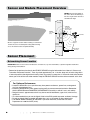
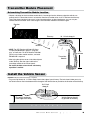
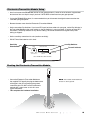
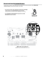
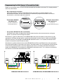
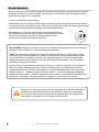
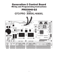
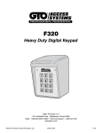
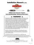
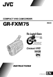
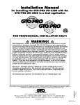
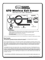
ACCESS
SYSTEMS
GTO Wireless Exit Sensor
IN S TA L LAT ION
MANUAL
Programmable
Dip Switches
Electronics/Transmitter
Module
Signal Cable
TRANSMITTER
MIN
MAX
CODE
SENSITIVITY
TRANSMITTER
TRANSMIT
ACTIVE
GTO WIRELESS EXIT WAND
MIN
MAX
CODE
SENSITIVITY
TRANSMIT
ACTIVE
GTO WIRELESS EXIT WAND
RB709U-NB
Universal Receiver
Module Cover
Vehicle Sensor
Kit Includes:
•
•
•
•
Wireless vehicle sensor with direct burial coil assembly and a plug-in electronics/transmitter
module designed for mounting up to 15 feet away from the pavement edge.
RB709U-NB two channel receiver with instructions.
Two size AA batteries.
GTO Wireless Exit Sensor instruction manual for general installation guidance.
Thank you for purchasing the GTO Wireless Exit Sensor. Please read the directions carefully and completely before installing.
How it works:
The GTO wireless exit sensor consists of a vehicle sensor, transmitter, and programmable dip switches.
The maximum range between transmitter and receiver is 80-100 ft.
The transmitter module transmits a special GTO transmitter code with additional information to tell the receiver
that this device should be treated as a “free exit” device. The latest GTO gate operators with blue control boards
(GTO “GEN3”) are able to decode this format and recognize the device as a free exit or open only command
without the use of the RB709U-NB receiver. This will simplify installations so only the original receiver will be
required.
The RB709U-NB receiver will be required unless you have the GEN 3 (blue board). The RB-709U-NB has two
channels that can be programmed to operate a remote transmitter or keypad and wireless wand. For instance,
Channel 1 could be wired to the Cycle and COM accessory terminals and could be programmed to operate a
transmitter and keypad. Channel 2 could be wired to the Exit and COM accessory terminals and could be used
to operate the wireless exit sensor. Depending on the frequency of use (vehicle traffic) the two AA batteries will
last about 1 to 3 years.
For more information on GTO's full line of automatic gate openers and access controls visit our website at www.gtoaccess.com
Rev. 12/01/08 • Printed in China for GTO, Inc.
Sensor and Module Placement Overview
NOTE: Place the transmitter on
the same side of the driveway in
the line of sight of the receiver to
maximize the range.
Driveway
SENSOR:
2 feet from
driveway (max)
and 12” deep
RANGE:
12 ft. radius
(max)
Transmitter
25 ft. from
gate (min)
Above is a typical location where installing a conventional
“wired” exit sensor would require cutting and trenching
across more than 50 feet of asphalt driveway.
100’ Max
Wireless
Open Gate
Outside
Sensor Range
Gate Opener
Receiver
Sensor Placement
Determining Sensor Location
IMPORTANT: Clear an area 20 feet in all directions of metal tools, toys and automobiles, to prevent magnetic disturbance
during testing and installation.
• Determine the optimum location for the VEHICLE SENSOR using the information found above in “Sensor and Transmitter Placement Overview”. Then dig a hole approximately 10 - 12 inches deep and 24 inches long within 2 feet and parallel to the edge of the driveway. Next, dig a trench no more than 15 ft from this hole to the location where you will install the transmitter module. Keep the VEHICLE SENSOR and the cable uncovered at this time.
For Optimum Performance:
•Locate the SENSOR as far as possible away from power transformers, power lines, underground
gas line, and telephone lines.
•Locate the SENSOR away from general moving traffic to prevent unwanted activation. Remember that the SENSOR detects MAGNETIC DISTURBANCES caused by a vehicle’s mass and velocity.
•Range distance is approximate and will vary due to outside interference, type of soil, vehicle mass, speed, etc.
•It is recommended that you run the Signal Cable inside PVC conduit to prevent accidental damage.
•Do not run Signal Cable in conduit with other wires such as AC power or other control wires.
• The SIGNAL CABLE CANNOT BE SPLICED. If you need more wire, contact the GTO Sales Department at 1-800-543-GATE (4283).
2
Wireless Exit Sensor
Transmitter Module Placement
Determining Transmitter Module Location
• Choose a location for the transmitter module that is far enough from the driveway edge that vehicles are unlikely to hit it. Fifteen feet of wire is included to allow the transmitter to be 12 to 15 feet from the driveway.
To test the chosen location to be sure it is free from obstructions or other interference, you can use your remote control transmitter at the same height as the transmitter module to activate the gate.
Receiver
10 -12 inch deep pit
Driveway
Vehicle Sensor
100 ft
Maximum
• NOTE: For GTO Receiver #AQ201-NB (Grey
in Color) R4500 Wireless Wand is “plug and play” and will work. For GTO Receiver #A2Q201 (Black) and all other model receivers, enclosed RB709U-NB is required.
15 ft
maximum
Transmitter
Module
• After laying the vehicle sensor in the hole adjacent to the driveway. Run the signal cable to the
transmitter module in the narrow trench.
Do not fill the hole or trench until satisfactory operation is verified.
Install the Vehicle Sensor
DO NOT fill the hole until final testing is complete.
• Dig a small pit about 10 - 12 inches deep close to the edge of your driveway. The hole should allow you to lay
the Vehicle Sensor flat in the bottom with the length of the Vehicle Sensor parallel to the direction of the driveway.
10-12 inch
deep pit
Vehicle Sensor
Placed 2 ft maximum
from edge of driveway
D
R
I
V
E
Vehicle Sensor should
lay parallel to driveway
W
A
Y
W i r e l e s s E x i t S e n s o r 3
Install the Electronics/Transmitter Module
NOTE: DO NOT place in the direct path of a sprinkler.
The module is water resistant but not waterproof.
6 inches
deep
•
Dig a narrow trench or slit from the Vehicle
Sensor to the transmitter location using a flat spade or other tool. The wire from the wand to the transmitter should be at least six inches deep to avoid possible damage from edgers, or lawn aerators.
Sensor
Connecting the Electronics/Transmitter Module
MED
TRANSMITTER
MIN
MAX
SENSITIVITY
CODE
TRANSMIT
ACTIVE
GTO WIRELESS EXIT WAND
• Feed the Signal Cable through the PVC pipe
and plug into the connector at the bottom of
the Electronics/Transmitter module.
4
Wireless Exit Sensor
Electronics/Transmitter Module Setup
• Install and connect the RB709U-NB receiver to your gate operator as shown in the instructions supplied with that receiver. You can skip this step if you have a GTO GEN3 control board on your gate operator.
• If using the RB709U-NB receiver, it is recommended that you disconnect the original antenna receiver that came with your gate opener.
• Remove the outer cover from the Electronics/Transmitter Module.
•
Set the transmitter Dip Switches. If you have GTO hand held transmitters for your gate, set the Dip Switches in
the Transmitter/Module to the same settings as the Dip Switches in your transmitter. If you do not have GTO
transmitters, set the Dip Switches to any desired setting. We do not recommend using the factory code setting as shipped.
• Set the sensitivity control to mid scale (medium sensitivity).
• DO NOT install the batteries at this time!
Sensitivity
Potentiometer
Dip Switches
MED
TRANSMITTER
MIN
MAX
SENSITIVITY
CODE
Transmit Indicator
TRANSMIT
ACTIVE
GTO WIRELESS EXIT WAND
Secure the Electronics/Transmitter Module on
the supplied PVC pipe by burying the bottom third
of the pipe in the soil and tamping the ground
around the pipe. DO NOT cover the electronics module with a metal cover as this will cause
signal interference.
This completes the hardware installation.
TRANSMITTER
CODE
MED
MIN
MAX
SENSITIVITY
TRANSMIT
ACTIVE
•
•
GTO WIRELESS EXIT WAND
Planting the Electronics/Transmitter Module
NOTE: The module should extend out
at least 12” above ground.
W i r e l e s s E x i t S e n s o r 5
To use or not to use the Included Receiver
Depending on the type of control board you are using you may or may not need to use the RB709U-NB
universal receiver included with the Wireless Exit Sensor.
• Post mount operators with a GEN-3 Blue Control Board DO NOT
require that you use the RB709U-NB universal receiver.
(See the pictures below to determine if you have a GEN-3 Blue Control Board).
• ALL PAD MOUNT OPERATORS will require the use of the
RB709U-NB universal receiver.
RB709U-NB
Universal Receiver
AUTO CLOSE TIME
STALL FORCE
STATUS
LEARN RMT
OFF
MAX
ON DIP
OFF
OFF
PULL
DLY.
OFF
OFF
MIN
1 2 3 4
SOFT START
WARNING
OPEN
SLV OPEN
MODE1
MODE2
120
ON
ON
PUSH
SIMULT.
ON
ON
S3
LEARN
MAST LIMIT
S2
LEARN
SLV LIMIT
S4
GEN-3 Blue Control Board
DOES NOT require the RB709U-NB universal receiver
6
Wireless Exit Sensor
Programming the Exit Sensor’s Transmitter Code
Before use, the receiver needs to “learn” the code transmitted by the wireless exit sensor. This simple procedure
takes only a few minutes.
•
Gen 3 (blue board) instructions
Set the 9 Dip Switches in the Transmitter Module to the same settings as the 9 Dip Switches in the
GTO Remote Transmitter. The Gen 3 (blue board) will automatically respond to the wireless exit sensor’s
transmission as a free exit or open only command.
Transmitter Module
Dip Switches
Set Same As GTO Remote
Transmitter Dip Switches
TRANSMITTER
MIN
MAX
TRANSMIT
ACTIVE
CODE
SENSITIVITY
+
0
Remote Transmitter
Dip Switches
1 2 3 4 5 6 7 8
Set Same As
Transmitter Module Dip Switches
ECE
GTO WIRELESS EXIT WAND
• For operators WITHOUT the Gen 3 (blue board)
Disconnect the red, black and green wires from the original receiver at the receiver terminals on the gate opener’s circuit board. It will no longer be needed.
Wire Channel 1 (green and blue wires) on the RB709U-NB to the Cycle and COM accessory terminals on the
gate opener. Hold down the gate opener’s remote transmitter button and the Channel 1 button on the RB709UNB at the same time. The red light on the RB709U-NB should blink once in 1 to 2 seconds to indicate that the
receiver has learned the code from the exit sensor.
Wire Channel 2 (yellow and brown wires) on the RB709U-NB to the Exit and COM terminals on the gate opener.
Install the two AA batteries in the wireless exit sensor’s transmitter module. This will immediately start 30 seconds
of transmissions from the wireless exit sensor. While the exit sensor is transmitting, hold down the Channel 2
button on the RB709U-NB. The red light on the RB709U-NB should blink once in 1 to 2 seconds to indicate that
the receiver has learned the code from the exit sensor.
OPEN
EDGE
CLOSE
EDGE
SHADOW
LOOP
EXIT/
OPEN
SAFETY
COM COM
CYCLE
CLOSE
GRN BLK
WHT
BLU
ORG
GRN
MIN
MAX
SEQ1
SEQ2
ON
STALL FORCE
LEARN
R
B
G
RED
RECEIVER
ALARM
CH 1 (Green Wire to Com)
CH 1 (Green Wire to Grn)
CH 1 (Blue Wire to Cycle)
CH 1 (Blue Wire to Blu)
CH 2 (Brown Wire to Com)
CH 2 (Brown Wire to Wht)
CH 2 (Yellow Wire to Exit)
CH 2 (Yellow Wire to Grn)
PRO3040-PCB Connections
ACCESSORY
RCVR
GTO/PRO1000, SL1000/2000 Connections
W i r e l e s s E x i t S e n s o r 7
Normal Operation
After the 30 seconds of “learn mode” transmission, the Vehicle Sensor performs an initial calibration sequence.
Calibration lasts about 15 seconds. DO NOT move the sensor, any vehicles, or large metal objects near the
Vehicle Sensor during this 15 second period.
Learning and calibration is now complete. Test the Vehicle Sensor by driving a vehicle along the driveway at a normal speed for the driveway (5-15mph).
The gate should open reliably when repeated several times. If the exit sensor does not open the gate every time,
try increasing (clockwise rotation) the setting of the sensitivity potentiometer.
When operation is satisfactory, install the outer cover over the Electronics/
Transmitter Module, fill the hole and trench with soil and tamp firm. Don’t be
alarmed if your gate opens while you are filling the trench and hole.
The metal in your shovel is activating the exit sensor.
TRANSMITTER
MIN
MAX
SENSITIVITY
GTO WIRELESS EXIT WAND
FCC WARNING: Changes or modifications to this unit not expressly approved by the party responsible for
compliance could void the user’s authority to operate the equipment.
NOTE: This equipment has been tested and found to comply with the limits for a Class B digital device,
pursuant to Part 15 of the FCC Rules. These limits are designed to provide reasonable protection against
harmful interference in a residential installation. This equipment generates, uses and can radiate radio
frequency energy and, if not installed and used in accordance with the instructions, may cause harmful
interference to radio communications.
However, there is no guarantee that interference will not occur in particular installations. If this equipment
does cause harmful interference to radio or television reception, which can be determined by turning
the equipment off and on, the user is encouraged to try to correct the interference by one or more of the
following measures: • Reorient or replace the receiver antenna. • Increase the separation between the
equipment and the receiver. • Connect the equipment into an outlet on a circuit different from that to which
the receiver is connected. • Consult the dealer or an experienced radio/TV technician for help.
This product and any accessory you purchase should only be installed on a gate opener
that meets the current safety standard, UL325, 4th Edition. If you have a gate opener
that is not listed with the current standard please contact the GTO sales department for
consultation on a gate opener that can meet your specific needs.
8
Wireless Exit Sensor
WARNING
When an EXIT SENSOR is in use, the automatic gate opener could be activated by a child on a
bicycle, tricycle or other metal play equipment. This product is not recommended for applications
exposed to children.
GTO Limited One Year Warranty
GTO, Inc., gate openers and accessories are covered under warranty by the manufacturer against defects in materials
and manufacturer workmanship for a period of one (1) year from date of purchase, provided the recommended installation
procedures have been followed.
In the case of product failure due to defective material or manufacturer workmanship within the one (1) year warranty
period, the product will be repaired or replaced (at the manufacturer’s option) at no charge to the customer, if returned
freight prepaid to GTO, Inc., 3121 Hartsfield Road, Tallahassee, Florida, USA 32303. IMPORTANT: Call (800) 543-1236 for
a Return Goods Authorization (RGA) number before returning accessory to factory. Products received at the factory
without an RGA number will not be accepted. Replacement or repaired parts are covered by this warranty for the remainder
of the one (1) year warranty period or six (6) months, whichever is greater. GTO, Inc. will pay the shipping charges (equal to
United Parcel Service GROUND rate) for return to the owner of items repaired under warranty.
The manufacturer will not be responsible for any charges or damages incurred in the removal of the defective parts for repair,
or for the reinstallation of those parts after repair. This warranty shall be considered void if damage to the product(s) was due
to improper installation or use, connection to an improper power source, or if damage was caused by lightning, wind, fire,
flood, insects or other natural agent.
After the one (1) year warranty period, GTO, Inc. will make any necessary repairs for a nominal fee. Call GTO at (800)
543-1236 for more information. This warranty gives you specific legal rights, and you may also have other rights which
may vary from state to state. This warranty is in lieu of all other warranties, expressed or implied. NOTE: Verification of the
warranty period requires copies of receipts or other proof of purchase. Please retain these records.
GTO, Inc. • 3121 Hartsfield Road • Tallahassee, Florida 32303
1-800-543-GATE (4283) • Technical Support 1-800-543-1236
www.gtopro.com
Technical Support Hours: MON - FRI 8:00AM - 7:00PM (ET)
(800) 543-1236
(850) 575-4144
W i r e l e s s E x i t S e n s o r 9