1
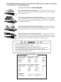
OWNER’S MANUAL GP-SW050 Residential Duty Swing Gate Operator TWO 12VDC, U1, 230A BATTERIES ARE REQUIRED BUT NOT INCLUDED. DO NOT Install This Operator Without Safety Edges and Photo Beams! APPROPRIATE ENTRY/EXIT DEVICES WILL BE REQUIRED - SEE YOUR DEALER. This product meets and exceeds the requirements of UL 325 gate operator safety standards. LISTED For more information on GTO’s full line of automatic gate openers and access controls visit our website at www.gtoaccess.com US GPSW050 rev - 04/07/08 Printed in China for GTO, inc. With Inherent UPS Battery Back-up System The GP-SW050 automatic gate operators are intended for use with vehicular swing gates. The operators can be used in Class I, II, III, and IV applications. vehicular gate operator class categories Class I: Residential Vehicular Gate Operator – A vehicular gate operator (or system) intended for use in a home of one-to-four single family dwelling, or a garage or parking area associated therewith. Class II: Commercial/General Access Vehicular Gate Operator – A vehicular gate operator (or system) intended for use in a commercial location or building such as a multifamily housing unit (five or more single family units), hotel, garages, retail store, or other building servicing the general public. Class III: Industrial/Limited Access Vehicular Gate Operator – A vehicular gate operator (or system) intended for use in an industrial location or building such as a factory or loading dock area or other locations not intended to service the general public. Class IV: Restricted Access Vehicular Gate Operator – A vehicular gate operator (or system) intended for use in a guarded industrial location or building such as an airport security area or other restricted access locations not servicing the general public, in which unauthorized access is prevented via supervision by security personnel. Warning! • READ ALL INSTRUCTIONS COMPLETELY before attempting installation and use; failure to do so may result in serious injury or death! • This unit must only be installed by an experienced technician! • DANGER: HIGH VOLTAGE! Contact with gate operator circuitry can cause serious injury or death! Operator power must be disconnected before servicing! • This gate operator may produce a high level of force. Stay clear of the unit while it is operating and exercise caution at all times. Conversion Chart Converting Metric Units to English Equivalents When You Know Multiply By To Find Symbol centimeters meters kilograms 0.3937 3.2808 2.2046 inches feet pounds in. (or “) ft. (or ‘) lb. (or #) Converting English Units to Metric Equivalents When You Know Multiply By To Find Symbol inches feet pounds 2.5400 0.3048 0.4535 centimeters meters kilograms cm m kg Temperature deg. Celsius deg. Fahrenheit (ºC x 1.8) + 32 deg. Fahrenheit ºF (ºF-32) / 1.8 deg. Celsius ºC Table of Contents Gate Operator Class Categories.......................................................................................Inside Cover Metric Conversion Chart...........................................................................................................................Inside Cover Safety Instructions for the GP-SW050 Swing Gate Operators.....................................................1 Important Safety Instructions for the System Designer.....................................................................................1 Important Safety Instructions for the Installer.......................................................................................................2 Important Safety Instructions Specific to Secondary Means of Protection Against Entrapment........3 Important Safety Instructions for the Consumer/End User...............................................................................4 Required Safety Precautions for Gates......................................................................................................................5 Warning Labels .................................................................................................................................................................6 Technical Specifications . .........................................................................................................................7 Parts Identification......................................................................................................................................8 Installing the Gate Operator....................................................................................................................9 Preparation of the Gate...................................................................................................................................................9 Operator Installation Overview...................................................................................................................................9 Using the Mounting Template ................................................................................................................................ 10 Mounting Template (not to scale) .......................................................................................................................... 11 Removing the Operator Housing ........................................................................................................................... 12 Mounting the Operator ............................................................................................................................................. 12 Connecting Power to the Operator ....................................................................................................................... 13 Connecting the Gate Arm Assembly....................................................................................................................... 14 Connecting Gate Arm to The Gate ......................................................................................................................... 15 Control Board Description.......................................................................................................................................... 16 Setting The Limits.......................................................................................................................................................... 17 Stall Force and Auto-Close Adjustments............................................................................................................... 18 DIP Switch Settings....................................................................................................................................................... 19 Input Connections......................................................................................................................................................... 20 Accessory Terminal Connections.............................................................................................................................. 21 Output Connections..................................................................................................................................................... 22 Accessory Power Supply.............................................................................................................................................. 23 Prison Mode Operation and Wiring A 3-Button Station................................................................................... 24 Reinstalling the Operator Housing ...................................................................................................................... 25 Installing a Dual System..........................................................................................................................26 Setting Dual Gate Sequence.................................................................................................................27 Overview of a Dual Gate Operator Installation..............................................................................28 Maintenance...............................................................................................................................................29 Troubleshooting Guide...........................................................................................................................30 Warranty and Repair Service . ..............................................................................................................33 Installation Checklist.............................................................................................................. Back Cover Important Safety Instructions Safety Instructions for the GP-SW050 SWING Gate OperatorS Because automatic gate operators produce high levels of force, all system designers, installers, and consumers have an obligation to know the potential hazards associated with improperly designed, installed, or maintained gate operator systems. Keep in mind that the gate operator is just one component of the total gate operating system. Each component must work in unison to provide the consumer with convenience, security, and safety. This manual contains various safety precautions and warnings for the system designer, installer, and consumer. Because there are many possible applications of the gate operator, the safety precautions and warnings contained in this manual cannot be completely exhaustive in nature. They do, however, provide an overview of the safe design, installation, and use of this product. CAREFULLY READ AND FOLLOW ALL SAFETY PRECAUTIONS, WARNINGS, AND INSTALLATION INSTRUCTIONS TO ENSURE THE SAFE SYSTEM DESIGN, INSTALLATION, AND USE OF THIS PRODUCT. The precautions and warnings in this manual are identified with these This warning symbols. symbol identifies the conditions that can result in serious injury or death from electrical shock. This symbol identifies the conditions that can result in damage to the operator or its components, serious injury, or death. Because GTO automatic gate operators are only part of the total gate operating system, it is the responsibility of the designer, installer, and purchaser to ensure the total system is safe for its intended use. Bypassing safety devices or neglecting to use safety devices with the gate operator is NOT acceptable. Important Safety Instructions for the System Designer WARNING: To reduce the risk of injury or death: 1. READ AND FOLLOW ALL INSTRUCTIONS. 2. This operator is intended for use only on vehicular gates. Pedestrians must be supplied with a separate walk-through gate (see Entrapment Protection on page 5). 3. When designing a system that will be entered from a highway or main thoroughfare, make sure the system is placed far enough from the road to prevent traffic congestion. 1 Important Safety Instructions Important Safety Instructions For the Installer WARNING–To reduce the risk of injury or death: I. Before Installation 1. READ AND FOLLOW ALL INSTRUCTIONS. 2. Verify this operator is proper for the type and size of gate, and its frequency of use. 3. Make sure that the gate has been properly installed and swing freely in both directions. Repair or replace all worn or damaged gate hardware prior to installation. A freely moving gate will require less force to operate and will enhance the performance of the operator and safety devices used with the system. 4. for pedestrian use (see page 5). NO ONE SHOULD CROSS THE PATH OF A MOVING GATE. II. During Installation 1. Install the gate operator on the inside of the property and fence line. DO NOT install an operator on the outside of the gate where the public has access to it. 2. Be careful with moving parts and avoid close proximity to areas where fingers or hands could be pinched. 3. Determine the best obstruction sensing setting for this installation. The gate MUST stop and reverse on contact with an obstruction. After adjusting the force or the limit of travel, retest the gate operator. Failure to adjust and retest the gate operator properly can increase the risk of injury or death (see page 18). 4. Additional safety equipment such as photo beams and safety edges MUST be installed to prevent bodily injury (see page 9). 5. Mount access controls away from the gate (minimum distance is 10 feet). The user must have full view of the gate but be unable to touch it while operating the controls. 6. Secure outdoor or easily accessed gate operator controls in order to prohibit unauthorized use of the gate. III. After Installation 1. Review ALL safety instructions with the consumer/end user and explain the basic operation and safety systems of the entire gate operator system. 2. Inform the consumer/end user that servicing of the operator must only be done by an experienced technician. 3. Attach the warning signs (included) to each side of the gate to alert public of automatic gate operation. Take a photo of warning signs installed on gate. Record the date of the photo for your reference. 4. SAVE THESE INSTRUCTIONS. with consumer/end user. 2 Leave IMPORTANT SAFETY INSTRUCTIONS (included) Important Safety Instructions Important Safety Instructions Specific to Secondary Means of Protection Against Entrapment As specified by Underwriters Laboratories Inc. UL 325 (30A.1.1), automatic gate operators shall have provisions for, or be supplied with, at least one independent primary and one independent secondary means to protect against entrapment. GTO gate operators utilize Type A, an inherent entrapment sensing system, as the primary type of entrapment protection. The GP-SW050 operators have provisions for the connection of Type B1, B2, or D protection to be used as the secondary type of entrapment protection. 1. For gate operators utilizing a non-contact sensor (Type B1) in accordance with UL 325 (51.8.4 [h]): A. Refer to the sensor manufacturer’s instructions on the placement of non-contact sensors for each type of application. B. Care shall be exercised to reduce the risk of nuisance tripping, such as when a vehicle trips the sensor while the gate is still moving. C. One or more non-contact sensors shall be located where the risk of entrapment or obstruction exists, such as the perimeter reachable by a moving gate or barrier. 2. For gate operators utilizing a contact sensor (Type B2) in accordance with UL 325 (51.8.4 [i]): A. One or more contact sensors shall be located at the leading edge, trailing edge, and post mounted both inside and outside of a vehicular swing gate system. B. A hard wired contact sensor shall be located and its wiring arranged so that the communication between the sensor and the gate operator is not subjected to mechanical damage. C. A wireless contact sensor such as one that transmits radio frequency (RF) signals to the gate operator for entrapment protection functions shall be located where the transmission of the signals are not obstructed or impeded by building structures, natural landscaping or similar obstruction. A wireless contact sensor shall function under the intended end-use conditions. 3. For gate operators utilizing an actuating device requiring continuous pressure to maintain opening or closing motion of the gate (Type D) in accordance with UL 325 (51.8.4 [e]): A. The gate operator controls must be placed so that the user has full view of the gate area when the gate is moving. B. Warning signs (see page 6) shall be placed adjacent to the controls. C. No other activation device shall be connected. ENTRAPMENT ALARM (UL 325; 30A.1.1A) The GP-SW050 operators are designed to stop and reverse for 2 seconds when the gate comes in contact with an obstruction or when an object activates the non-contact sensors. Additionally, these operators are equipped with an audio entrapment alarm which will function if the unit obstructs twice while opening or closing. This alarm will sound for a period of 5 minutes or until the operator receives an intended signal (e.g., transmitter signal) and the gate returns to a fully open or fully closed position. 3 Important Safety Instructions Important Safety Instructions for the Consumer/End User WARNING: To reduce the risk of injury or death: 1. READ AND FOLLOW ALL INSTRUCTIONS. 2. Distribute and discuss copies of the IMPORTANT SAFETY INSTRUCTIONS manual with all persons authorized to use your gate. SAVE THESE INSTRUCTIONS. 3. Always keep people and objects away from the gate and its area of travel. NO ONE SHOULD CROSS THE PATH OF THE MOVING GATE. 4. Your automatic gate is not for pedestrian use. If pedestrian traffic is expected near the gate, a walkthrough gate must be installed for this purpose (see page 5). 5. Do not allow children or pets near your gate. Never let children operate or play with gate controls. Keep the remote controls away from children and unauthorized users; store controls where children and unauthorized users do not have access to them. 6. If push buttons or key switches are installed, they should be within sight of the gate, yet located far enough from the gate (at least 10 feet) so the gate cannot be touched while in operation. Do not operate any control without watching the movement of the gate. 7. Do not activate your gate operator unless you can see it and can determine that its area of travel is clear of people, pets, or other obstructions. 8. It is your responsibility to make sure that the installer posted warning signs on both sides of your gate. If any of these signs or warning decals become damaged, illegible or missing, replace them immediately. Contact your installer or GTO for replacements. 9. Verify that electric safety edge sensors or photoelectric sensors have been installed (see page 5). These safety devices should be tested monthly. 10. KEEP GATES PROPERLY MAINTAINED. Have a qualified service person make repairs to the gate hardware. NEVER REMOVE THE OPERATOR HOUSING. 11. DANGER: HIGH VOLTAGE! Contact with gate operator circuitry can cause serious injury or death! DO NOT attempt to service this operator yourself; for service, contact your installer or another experienced technician. 12. Have your gate operator tested monthly and serviced regularly by an experienced technician. The gate MUST stop and reverse on contact with an obstruction or when an object activates the non-contact sensors. If these functions are observed to operate improperly, discontinue use and have operator serviced immediately. 4 Important Safety Instructions Required Safety Precautions for Gates Entrapment Protection GTO’s internal obstruction settings, even when properly adjusted, may not be sensitive enough to prevent bodily injury. For this reason, safety devices such as safety edges and photo beams MUST be installed. Furthermore, a walk-through gate must be installed if pedestrian traffic is expected near the gate. We recommend the GTO Bulldog Pedestrian Gate Lock (available as an accessory) for controlled access. Pedestrian Gate Safety Edge Warning Sign Safety Edge Vehicle Gate Safety Edge Photo Beams Photo Beams ! WARNING Warning Signs Moving Gate Can Cause Injury Or Death The warning signs (with orange panel) must be installed on both sides of the gate. 1. KEEP CLEAR! Gate may move at any time. 2. Do not allow children to operate gate or play in gate area. 3. This gate is for vehicles only. Pedestrians must use a separate entrance. 5 Operator Important Safety Instructions Warning Labels These warning signs and labels should be found at the locations specified below. If any of them are missing, immediately contact your installer for replacements. ! WARNING Moving Gate Can Cause Injury Or Death 1. KEEP CLEAR! Gate may move at any time. 2. Do not allow children to operate gate or play in gate area. 3. This gate is for vehicles only. Pedestrians must use a separate entrance. Warning signs (2) to be installed on each side of the gate (3–5 feet above the bottom of the gate) GTO AC GP-SW050 SERIES C LIS ED T #xxxxxxx US Conforms to UL 325 STANDARDS Maximum Gate: 650 lb. (295.4 kg); 16 ft. (4.9 m) Voltage: 110 Vac; Frequency: 60 Hz; Power: 300 W Class I, II, III and IV Vehicular Swing Gate Operator. Serial Number: XXXXXXXXXX TO MANUALLY OPEN AND CLOSE THE GATE: 1. Turn control box power switch OFF. 2. Disconnect operator arm from gate brackets. 3. Manually swing gate to desired position. Disconnect operator ONLY when the control box power switch is OFF and the gate is NOT moving. xx/xx/xx GTO, Inc. Tallahassee, Florida USA GP-SW050 Product identification and manual operation instruction label (1) installed on cover. 6 Technical Specifications Motor • Brushless DC motor 24VDC 300 watts • ½ Horsepower • Maximum motor current 20Amp • 2500 RPM • Open and close time for 90° opening is approximately 15 seconds Gear Reducer • Aluminum Cased 1200:1, size 40/63, compound, worm reducer with ball bearings. • Permanently lubricated with synthetic gear oil – oil specifications 5w-30, Mobil 1 recommended Power • 120 vac @60 Hz with inherent 24 vdc battery backup • Batteries are required – two 12 vdc, U1, 230A minimum cold crank amps wired together in series. • 100 cycles in backup typical for minimum size battery. • 15 amp circuit breaker on dedicated circuit • On board 120 vac outlet for accessories that pull no more than 1 amp of current Control • Microcontroller based logic control board • Adjustable autoclose • Independent obstruction settings • Diagnostic LED’s & Audible Alarms • Accessory terminals compatible with loop detectors, photo beams, edge sensors, push buttons, card readers, exit wands, etc. • Relay Outputs • On board Open and Closed Stop buttons • Jog Buttons Construction • Heavy duty steel frame • Rotomolded UV stabilized HDPE cover Operational Capacity • Continuous duty operations • Max rating: 16 ft gate @ 650 lbs • Dual Gate compatible using two conductor 22 AWG shielded wire rated for direct burial. Recommended Belden Wire®, 22 AWG, type 8761, 9461, 9451, 1266A or equivalent. 1-pair shielded with drain wire. Available at your local electrical supply store. Dimensions • Housing Dimensions: height 33 in (68.7 cm), depth 18 in (45.7 cm), width 15 in (38 cm), shipping weight: 130 lbs • Concrete Pad Dimensions: 18 in x 18 in, (45.7 cm x 45.7 cm). Consult local building codes for depth below ground level. Absolute minimum depth 30 in (76.2 cm) below ground level. Operational Temperature: • In colder climates (ambient temperatures less than 10 degrees) GTO recommends the use of a thermostatically controlled heating source (ceramic heating strips, etc.) on the batteries and gearbox assembly. Styles, types, and power requirements of heating devices will vary by climate and region. Warranty: • Residential (7) years for mechanical parts, (5) years electronic components • Commercial (5) years for mechanical parts, (3) years electronic components 7 Parts Identification Fully Assembled Operator 13 in (33 cm) Operator Chassis 12½ in (31.8 cm) 17 in (42 cm) 27 in (69 cm) 23¾ in (60.3 cm) 19¾ in (50.2 cm) 24 in (61 cm) 33 in (84 cm) TO BASE 18 in (46 cm) 6 in (15.2 cm) 15 in (38 cm) NOTE: GTO receiver (RB709U), batteries (12vdc, U1, 230A minimum) not included. Must order separately. 14½ in (36.8 cm) 12½ in (31.8 cm) 3 in (7.6 cm) Owner’s Manual GTO/PRO GP-SW050 AC Powered Swing Gate Operators WARNING Gate Bracket Gate Warning Signs (one for each side) Owner’s Manual Reducer /Operator Arm HARDWARE BAG - R4027 1/2" Nut (2) Clevis Pin (1) 1/2" Washer (2) Plastic Spacer (1) ½" – 2¾" Bolt (2) 8 Hairpin Clip (1) Installing the Gate Operator This unit must only be installed by an experienced technician. Preparation of the Gate Before installing the GTO swing gate operator, make sure: • the gate is properly installed. • the gate is plumb, level, and moves freely. • the gate does not bind or drag on the ground. Overview of a Single Gate Operator Installation The diagram below is an example of a single swing gate installation with required safety features. The operator must be installed on the inside of the gate. You must install safety edges and photo beams (not included) to reduce the possibility of bodily injury. NOTE: A separate gate or entrance must be installed for pedestrian use. Safety Edge Safety Edge Warning Sign Receiver Operator Safety Edge Use PVC conduit for Receiver wire AC POWER Photo Beams Photo Beams Use rigid conduit for inbound AC wire. Photo Beam Photo Beam 9 Using the Mounting Template The mounting template (see insert) is designed to simplify mounting the operator. It provides the installer with the proper locations for running power and accessory wiring conduits. The template is also marked with the correct distance between the operator mounting holes and shows the installer how to position the operator for the correct clearance between the housing and the gate. NOTE: The operator must be securely mounted on a level concrete pad. If you do not have an existing pad to work with, be sure to install wiring conduit before pouring concrete. You must use (5) 3/8” diameter wedge type mounting anchors, washers, and nuts (not included) to mount the operator on the pad. Study the mounting template. Lay the mounting template on the level concrete pad and mark the pad according to the instructions on the template. Before mounting the operator, check the following: • The concrete pad is level. • (6) 3/8” diameter mounting anchors are in their correct positions. • Conduit for power and accessory wiring is installed. Mounting Operator Concrete mounting pad 16 in x 16 in. Consult local building codes for depth below ground level. Absolute minimum depth 30 in (76.2 cm) below ground level. Use 3/8 in (.95 cm) diameter concrete mounting bolts in mounting pad. 6 Concrete Mounting Bolts 3/8” diameter not included 33 in (83.8cm) TO BASE 16 in (45.7cm) 16 in (45.7 cm) 6 3 /8 in (16.2 cm) GROUN D LEVE 10 in (25.4 cm) 4 5 /8 in (16.2 cm) 30 in (76.2 cm) MINIMUM BELOW GROUND LEVEL 10 L Mounting Template (NOT TO SCALE) Drill 3/8” x 3” deep 6 places. Use 3/8” wedge type anchors. 3” Output Shaft 4 5/8” 6 3/8” 2½” Gate open position 11” 10” Gate closed position 18½“ From Hinge Centerline Concrete pad 16” x 16”. Consult local building codes for depth below ground. Absolute minimum depth 30” below ground level. Hinge centerline Gate post 7“ From Hinge Centerline 11 Removing the Operator Housing Before you can gain access to the operator frame and its mounting holes, the housing will have to be removed from the operator. 1. Remove the (2) 3/8” allen bolts and (2) m8 washers from the operator housing (this hardware is located on each side of the housing). 2. Lift the housing off the operator and set it aside. Allen Bolts with 5mm key Washers Mounting the Operator 1. Lift the operator and align its mounting holes over the 3/8” diameter concrete mounting anchors. 2. Lower the operator into position and fasten it to the mounting anchors with (4) 3/8” washers and nuts (not provided). 12 Connecting Power to the Operator 1. Turn the breaker power switch off before connecting AC power. Have a licensed electrician run 115 Vac wiring into the Field Wiring Connection Compartment. The 115 Vac line will power the gate operator system. The circuit must be protected with a 15 A main disconnect breaker (not provided). NOTE: Power and wiring connections MUST be performed by a licensed electrician in accordance with NEC (National Electric Code) and local codes. NEVER run low voltage (e.g., accessory or receiver) wires in conduit containing 115 Vac wiring. 2. Connect batteries to operator as shown. The red wire connects to the positive terminal in the control box. The black wire connects to the negative terminal in the control box. The jumper wire (included) connects both batteries together with the remaining terminals. Wire the 24V system in series as shown below. 3. Turn on AC power at this time. RED WIRE to positive (+) JUMPER WIRE (Supplied) negative (-) to positive (+) NOTE: Battery should be a 12 Vdc, U1, 230 Amp Minimum, Lead Acid Battery (Typical Lawn and Tractor Battery). BLACK WIRE to negative (–) NOTE: When first turning operator power switch on, the unit may beep once every 5 seconds until the new batteries can be fully charged (30-60 minutes charging time). 13 Gate Arm Connection Overview Right Mounted Arm Center point of gate hinge to center of gate bracket pin (approximately) 50” Center point of gate hinge Column Closed Gate Range of Arm Movement 160°-175° 5°-10° Housing Pivot point of operator Opened Gate e CAUTION: DO NOT STAND IN THIS AREA IMPORTANT: Be sure the operator housing will not be hit by a fully open gate and that the gate column will not interfere when housing is installed. NOTE: All work on operator requires disconnecting AC power and batteries ! 14 Connecting the Gate Arm to the Gate Key Bolts and Washers Output Shaft Reducer Arm Fig. 1 Fig. 2 1. Install the key into the output shaft. (Fig. 1) 2. Fit the end of the reducer arm onto the output shaft as shown and tighten the bolts. (Fig. 2) 3.Turn the power on. 4.Set DIP switch 1 to designate the operator arm as left or right (Fig. 3) (right is shown here). 5. Manually move gate to the closed position. (Fig. 4) ON ON ON >>> SIMUL SLAVE SECURE MODE 1 MODE 2 OPEN DIR. SLV OPN DUAL MODE LOW BATT Fig. 3 Closed Gate Operator Arm (approx) 5°-10° Angle Clevis Pin 1 2 3 4 Gate Bracket OPTIONS OFF OFF <<< DELAY MASTER SAFE Reducer Arm Fig. 4 Hairpin Clip Closing Fig. 5 CAUTION: DO NOT STAND IN THIS AREA 6. Unfold the arm to approximately a 5-10° angle. (Fig. 4) 7. Use ‘CLOSE’ button on control board to move operator arm/reducer arm to the gate. CAUTION: Be careful not to stand in the gray area surrounding the operator. (Fig. 4) Be prepared to stop (using the ‘STOP’ button) when the gate arm and reducer arm near the desired position. NOTE: Use ‘JOG’ buttons to fine tune the position. 8. Mark the position of the gate bracket holes on the gate, drill holes and mount bracket. 9. Fit the end of the operator arm into the gate bracket and attach using clevis pin and hairpin clip. (Fig. 5) NOTE: Gate Arm’s length can be adjusted by rotating the gate arm’s tube before mounting it to the gate bracket. (Fig. 5) Fig. 6 15 EXIT SHADOW SAFETY GTO LOOP DETECTORS ALARM 3 COM LINK COM DUAL CABLE DUAL LINK ACC. POWER 5 BLDC SPEED CONTROL LOCK 13 RUNNING 12 CLOSED 11 20 LOCK COM LOCK N.O. RUN 2 RELAY OUTPUTS RUN 1 DIAG. PORT OPTIONS CLOSED 2 10 CYCLE CYCLE SAFETY SAFETY 9 OPEN EDGE CLOSE EDGE CLOSE EDGE OPEN OPEN CLOSE CLOSE STOP STOP COM COM COM COM W1 CUT TO USE 3 BUTTON STATION MODE 1 MODE 2 OPEN DIR. SLV OPN DUAL MODE LOW BATT AUTO CLOSE TIMER >>> 18 17 MIN MAX MIN LIMIT ADJUSTMENTS <<< JOG >>> 21 CLOSE COM COM ON ON >>> SIMUL SLAVE SECURE STALL FORCE ADJUST <<< SHADOW SHADOW LOOP OPEN EDGE 19 1 2 3 4 OFF OFF <<< DELAY MASTER SAFE CLOSED 1 ON 8 LIMIT SENSORS DUAL LINK 14 7 1 AT OPEN LIMIT PRISON MODE + ACC. PWR. 12VDC - 300ma LOCK N.C. 6 2 STATUS +12Vdc 4 COM +12V OPEN COM COM +12V OPEN COM COM +12V OPEN COM Control Board Description MAX 16 TEST SWITCHES STOP 15 OFF 120 SET LIMIT OPEN GTO Inc. Tallahassee, FL SX4000 Logic Board Rev. E 1 BLDC Motor Control Connection 12 LED Indicator - To Show ‘Running’ Relay is on 2 Limit Sensor Connection 13 LED Indicator - To Show ‘Lock’ Relay is on 3 Alarm / Buzzer Connection 14 LED Indicators - To Show Dual Link Communication 4 12Vdc Accessory Power 15 Test Switches - To Control Gate Operation 5 Dual Link Connection 16 Limit Adjustment Control Switches 6 Relay Output - To Control Lock 17 Left and Right Stall Force Adjustment 7 Relay Output - To Indicate Gate’s Running 18 Auto Close Timers Adjustment Potentiometer (OFF, 3-120 sec) 8 Relay Output - To Indicate Gate’s Closed 19 DIP Switch Option Setting 9 Accessory Inputs 20 Diagnostic Port (NOT for telephone) 10 LED Indicators - For accessory inputs 21 W1- for 3-button Station with Normally Close ‘Stop’ Button 11 LED Indicators - To show ‘closed’ relay is on 16 Setting the Limits CAUTION: Be extremely careful not to stand in the path of the gate arm while setting limits. OPEN LIMIT SETTING: 1. Turn on operator power. 2. Press and release the OPEN button on the board and be prepared to press the STOP button when the gate reached the desired open position/limit. 3. The JOG buttons can be used to bring the gate to the precise open position. The JOG buttons will slowly run the gate when pressed and stop the gate when released. 4. Once at the desired open position, press and hold the SET LIMIT button for 3 seconds or until the alarm sounds and STATUS LED is on. At this time, release the SET LIMIT button. 5. Be prepared to stop the gate when it reaches the closed position. CLOSED LIMIT SETTING: 1. If not already closed, press and release the close button. 2. Press and release the CLOSE button on the board and be prepared to press the STOP button when the gate reached the desired closed position/limit. 3. The JOG buttons can be used to bring the gate to the precise closed position. The JOG buttons will slowly run the gate when pressed and stop the gate when released. 4. Once at the desired closed position, press and hold the SET LIMIT button for 3 seconds or until the alarm sounds and STATUS LED is on. At this time, release the SET LIMIT button. 5. Open the gate to allow it to stop on its own. CYCLE FORCE ADJUST 6. Open and close the gate to verify proper operations. IfSTALL limits are not set SAFETY <<< >>> properly, redo limit setting steps above. AUTO CLOSE TIMER NOTE: If limits are too short, use jog button to move arm short distances to stop gate at OPEN EDGE the precise open or closed position. CLOSE RUN 2 EDGE OPEN OPEN CLOSE CLOSE STOP STOP COM COM COM COM COM MIN MAX MIN MAXMAXOFF OFF LIMIT ADJUSTMENTS LIMIT ADJUSTMENTS <<<<<<JOG JOG>>>>>> W1 CUT TO USE 3 BUTTON STATION CLOSE COM GTO Inc. Tallahassee, FL SX4000 Logic Board Rev. E 17 SWITCHES TESTTEST SWITCHES STOP SET SET LIMIT LIMIT OPEN 120 120 Stall Force and Auto-Close Adjustments Stall Force Adjustment: IMPORTANT: For safety reasons, the STALL FORCE potentiometers are set at the “10 o’clock” position at the factory. The obstruction sensitivity is independently adjustable for each direction of travel. Upon sensing an obstruction, the gate will stop and reverse direction for approximately 2 seconds. 1. Turning the potentiometer clockwise (toward the MAX position) increases the amount of force the operator applies to an obstruction. Turning the potentiometer counter-clockwise (toward the MIN position) decreases the amount of force the operator applies to an obstruction. LOCK N.C. 2. Use a small screwdriver to adjust the appropriate potentiometer and operate the gate until it can LOCK COM run without obstructing and reversing direction. LOCK N.O. RUN 2 RELAY OUTPUTS RUN 1 RUNNING DIAG. PORT LED10 OPTIONS CLOSED CLOSED 1 CYCLE CYCLE SAFETY SAFETY SAFETY SHADOW SHADOW LOOP OPEN EDGE CLOSE RUN 2 EDGE CLOSE EDGE OPEN OPEN OPEN CLOSE CLOSE CLOSE STOP STOP STOP ON ON >>> SIMUL SLAVE SECURE STALL FORCE ADJUST <<< SHADOW OPEN OPEN EDGE EDGE ON CLOSED 2 1 2 3 4 OFF OFF <<< DELAY MASTER SAFE LED09 MIN AUTO CLOSE TIMER >>> MAX MIN LIMIT ADJUSTMENTS <<< JOG >>> MODE 1 MODE 2 OPEN DIR. SLV OPN DUAL MODE LOW BATT MAX OFF 120 SET LIMIT COM COM Auto-Close Adjustment: COM COM The Auto-Close potentiometer allows the user to set the time that the gate will stay at the open position/limit before it automatically starts to close the gate. This feature can be turned off by turning the AUTO CLOSE TIMER potentiometer all the way counter- clockwise. It is shipped from the factory in the OFF position (auto close feature is disabled). • The auto close time is adjustable from 3-120 seconds. • This feature is only enabled when the gate is at the open limit. • This feature is disabled if the following inputs are activated. • OPEN, SAFETY, SHADOW, CLS-EDGE or STOP. 18 DIP Switch Settings MODE 1 & MODE 2: • Reserved for future features DIP #1: OPEN DIRECTION • OFF: for gate that opens to the left, closes to the right. • ON: for gate that opens to the right, closes to the left. • • BLDC SPEED CONTROL PRISON MODE OFF: Fail safe mode DUAL LINK When low battery and no AC power conditions are detected the gate will automatically run to the opened position. The gate will remain at the open position until AC power is restored and the battery reaches an acceptable charge level. LOCK N.C. LOCK ON: Fail secure mode LED11 When low batteryLOCK isCOM detected and no AC power is present, the gate will automatically LOCK N.O. run to the closed position. Gate will RUNNINGis enabled and gate is at auto close only if auto close feature LED10 RUN 1 open limit. The gate will remain at the closed position until AC power is restored and the battery reaches an RUN 2 acceptable charge level. CLOSED These switches are for dual gate applications only. See page 26 for dual gate settings. DIAG. PORT RELAY OUTPUTS CLOSED 1 LED09 CYCLE SAFETY SAFETY OPEN EDGE RUN 2 OPEN OFF OFF <<< DELAY MASTER SAFE ON CYCLE OPTIONS 1 2 3 4 CLOSED 2 SHADOW LOOP ON OFF DIP #3: MASTER/SLAVE (applicable to dual gate installation only) • NOTE: This DIP switch is applicable if and only if all the following conditions are valid: • Dual Link cable is connected. • The second operator is detected by the master. • If the above conditions are not met, the board will default to single mode operation. If DIPEXIT #3 is OFF (Master) SAFETY SHADOW LIMIT SENSORS • OFF: Master mode ALARM operation inGTO dualLOOP gate installation DETECTORS if slave setting is detected from the other board. STATUSif master • ON: Slave mode operation in dual gate installation setting is detected from the other board. Control board is nonAT OPEN LIMIT functional if master operator is not detected. + ACC. PWR. 12VDC 300ma DIP #4: FAIL SAFE/FAIL SECURE -OPERATION ON 1 2 3 4 DIP #2: SLAVE OPEN SEQUENCE (dual gate installation only) • NOTE: This DIP switch is applicable if and only if all the following conditions are valid: • DIP switch #3 is OFF (Master mode) • Dual Link cable is connected. • Slave mode is detected from the second board (DIP switch #3 of the second board is ON) • If the above conditions are not met, the board will default to single gate operation. If DIP #3 is OFF (Master) • OFF: Slave gate will open after the master gate. • ON: Slave gate will open simultaneously with the master gate. ON ON >>> SIMUL SLAVE SECURE STALL FORCE ADJUST <<< SHADOW OPEN EDGE 19 >>> MODE 1 MODE 2 OPEN DIR. SLV OPN DUAL MODE LOW BATT AUTO CLOSE TIMER E LINK COM LOCK N.C. Input Connections LOCK LOCK COM RELAY OUTPUTS LOCK N.O. NOTE: • All control inputs are dry-contact, normally open, inputs except for #8. DO NOT apply external voltage RUN 1 sources to these inputs. • All inputs are connected with respect to COMMON terminal. RUN 2 • All inputs have a corresponding LED indicator for diagnostic purposes. All input LED indicators, except for the STOP LED, will be dimly lit when its corresponding input is inactive and brightly lit when it is activated. RUNNIN CLOSED CLOSED 1 1 CYCLE: (Typically for use with doorbell button or hardwired key pad) • Each activation at this input will cycle the operation as follows: ….→ OPEN → STOP → CLOSE → STOP → OPEN → … 2 SAFETY: (Typically for use with photo beam device, loop detector or other non-contact sensors) • Activation of this input while the gate is closing will cause the gate to stop and return to the opened position. • Activation of this input while the gate is opening has no effect (gate will continue to open). • Activation of this input while gate is idle will prevent gate from closing. 3 SHADOW: (Typically for use with loop detector device) • This input is only monitored when the gate is at the fully open position. At any other position, activation of this input has no effect on gate operation. • Activation of this input while gate at the fully open position will prevent gate from closing. 4 OPEN EDGE: (Typically for use with safety edge device) • Activation of this input while the gate is opening will cause the gate to stop and reverse direction for approximately 2 seconds. • Activation of this input while the gate is closing has no effect (gate will continue to close). • Activation of this input while gate is idle will prevent gate from opening. CLOSED 2 CYCLE 1 2 3 OPEN EDGE 5 CLOSE EDGE 6 OPEN CLOSE 8 STOP 9 COM COM 7 CLOSE: (Typically for use with 3-button control station) • Activation of this input will close the gate if it is idle AND not already at the closed position. • Activation of this input while gate is opening will stop the gate. STOP: (For use with 3-button control station that has ‘NORMALLY CLOSED’ STOP button) • Activation of this input will stop the gate. • Jumper ‘W1’ must be cut when using normally closed ‘STOP’ button. • A normally closed button must be connected to ‘STOP’ and ‘COM’ in order for gate to operate. 20 7 6 OPEN: (Typically for use with exit loop or wand) • Activation of this input will open the gate if it’s not already at the open position • Activation of this input while at open limit will restart the auto close time (if enabled). 9 COM: Circuit common (reference for all accessory inputs) • Three (3) terminals to provide extra common connection point. SHADOW LOOP 4 5 CLOSE EDGE: (Typically for use with safety edge device) • Activation of this input while the gate is closing will cause the gate to stop and reverse direction for approximately 2 seconds. • Activation of this input while the gate is opening has no effect (gate will continue to open). • Activation of this input while gate is idle will prevent gate from closing. 8 SAFETY COM COM COM COM GTO Inc SX4000 L CLOSE MA LIMIT AD <<< COM GTO Inc. Tallahassee, FL W1 CUT TO USE 3 BUTTON STATION COM COM COM COM STOP OPEN SAFETY CLOSE 12 13 14 15 16 17 18 19 20 21 22 CYCLE CLOSED 2 CLOSED 1 COM STOP CLOSE OPEN CLOSE EDGE SHADOW OPEN EDGE SAFETY CLOSED 9 10 11 RUN 2 LOCK N.O. LOCK N.C. LOCK COM LINK COM 8 RELAY OUTPUTS CLOSE EDGE 7 SHADOW LOOP 6 OPEN EDGE 5 4 DUAL CABLE RUN 1 3 DUAL LINK COM +12Vdc ALARM 12v power supply can be used for loop detectors, receivers, photo beams, keypads and other accessories. LOCK DUAL LINK 2 ACC. POWER RUNNING CYCLE AT OPEN LIMIT PRISON MODE + ACC. PWR. 12VDC - 300ma STATUS EXIT SHADOW SAFETY GTO LOOP DETECTORS 1 SX4000 Logic Board Rev. E MIN STALL F <<< OFF OFF <<< DELAY MASTE SAFE LIMIT SENSO Accessory Terminal Connections COM OPEN +12V COM 1 2 22 13 14 17 17 OPEN 18 CLOSE 19 STOP ON DIP NO COM NC V+ V– LOOP LOOP 1 2 3 4 5 6 7 8 9 10 20 GTO Loop Detector LOOP 3 Button Station SOS 17 20 13 Siren-Activated Entry Device 20 GTO Photo Beams 20 20 12 17 GTO Universal Receiver Refer to Universal Receiver manual for additional connections GTO Exit Wand Refer to Exit Wand manual for additional connections 20 15 16 Edge Sensor 1 4 21 NOTE: Connections are for typical applications. There may be additional connection options for applications that are not illustrated here. 2 ABC 5 GHI JKL 7 PRS 8 TUV 3 DEF 6 MNO 9 WXY 0 12 GTO Keypad 21 Output Connections LOCK COM LOCK N.O. Maximum rating for all relay outputs are 24Vac/dc, 1 Amp. All relay outputs are dry contact (no voltage) switching. All outputs have corresponding LED indicator for diagnostic purposes. The corresponding LED indicator will be lit when its relay is activated. RUN 1 RUN 2 RELAY OUTPUTS Note: • • • LOCK N.C. RUNNING LED10 CLOSED CLOSED 1 1. CLOSED 1 and CLOSED 2: At closed limit relay output. • These two (2) terminals are shorted when gate is at the closed limit. LED09 CLOSED 2 2. RUN 1 and RUN 2: Gate moving relay output. • These two (2) terminals are shorted whenever the gate is moving/running. 3. LOCK COM and LOCK N.O. / LOCK N.C.: Lock relay output • This relay output is designed for use with either mechanical or mag-lock device. The relay is activated (releasing the lock) during the first and the last 2-4 seconds of gate running. Example A: Mag-Lock Connection: Use LOCK COM and LOCK NC terminals. The diagram below is for a typical mag-lock connection. Refer to the mag-lock manual for detailed operations. Example B: For locks that are energized to release: Use LOCK COM and LOCK NO terminals. LOCK N.C. Example A LOCK LED11 LOCK COM LOCK N.O. RUN 1 To positive (+) terminal of mag-lock power supply RUN 2 RELAY OUTPUTS Mag Lock 24vDC Max, 1 Amp Max RUNNING LED10 CLOSED To negative (-) terminal of CLOSED 1 mag-lock power supply LED09 CLOSED 2 LOCK N.C. Example B LOCK LED11 LOCK COM LOCK N.O. RUN 1 To positive (+) terminal of Lock power supply RUN 2 To negative (-) terminal of CLOSED 1 Lock power supply CLOSED 2 22 RELAY OUTPUTS Lock Coil or Controller 24vDC Max, 1Amp Max RUNNING LED10 CLOSED LED09 Accessory Power Supply Connection • • 12Vdc @ 300 mA (.3A) maximum power supply for additional accessories. If you lose power to your accessories, the accessories are protected by a poly-fuse. Disconnect accessories and allow poly-fuse to cool down for 2 minutes before reconnecting. EXIT SHADOW SAFETY ALARM GTO LOOP DETECTORS STATUS +12Vdc COM LINK COM 23 DUAL CABLE DUAL LINK ACC. POWER 12Vdc @ 300 mA Power Supply + ACC. PWR. 12VDC - 300ma DUAL LINK AT OPEN LIMIT PRISON MODE Prison Mode Operation (CLASS IV APPLICATIONS) Prison mode operation means that constant pressure at the CLOSE or the OPEN push button station input is required to move the gate in the desired direction. Follow these steps to toggle the PRISON MODE operation on/off: 1. Power down the unit. 2. Press and hold the OPEN and CLOSE push button while powering on the unit. CYCLE 3. The PRISON MODE LED indicator will be on if operating in prison mode. AUTO CLOSE 4. Repeat the above steps SAFETYto turn off prison mode operation. <<< SHADOW TIMER >>> CYCLE OPEN EDGE CLOSE EDGE SAFETY OPEN CLOSE SHADOW STOP COM COM COM COM MIN MAX MAX LIMIT ADJUSTMENTS <<< JOG >>> OPEN EDGE W1 CUT TO USE 3 BUTTON STATION CLOSE EDGE MIN TEST SWITCHES STOP CLOSE OFF 120 SET LIMIT OPEN GTO Inc. Tallahassee, FL SX4000 Logic Board Rev. E OPEN CLOSE STOP COM COM Press and hold at power up to toggle to prison mode. W1 CUT TO USE 3 BUTTON STATION CYCLE COM Wiring a 3-button station SAFETY SHADOW LOOP OPEN EDGE NOTE: The W1 Jumper must be cut in order to use a 3-button station. CLOSE EDGE OPEN To restore normal operation of cut jumper you must connect a wire between the STOP and COM terminals (or you could use a normally closed push-button). This wire functions the same as the W1 jumper. CLOSE OPEN CLOSE STOP STOP COM COM COM 24 Reinstalling the Operator Housing Check to make sure the safety edges, photoelectric beams, warning signs, and pedestrian gate (if necessary) are installed (see pages 5-6) before fastening the housing to the operator. 1. 2. Lower the operator housing into position over the operator. 3. Pull sides out slightly so that the housing sits into place properly over the base. Fasten the housing to the operator with (2) Washers and (2) Allen Bolts. Allen Bolts with 5mm key Washers The installation is complete. Test the operator, accessories, and safety devices for correct function. Read and fill out the INSTALLATION CHECKLIST on the back cover of this manual. 25 Installing a Dual Gate Operator System IMPORTANT: With a dual gate system certain control board settings and connections are required on the MASTER unit only and some are required on both the MASTER and the SLAVE unit. The list below gives an overview. • • • • • • Gate Sequencing - DIP #2 on Master Unit Alarms - wired to MASTER only Entry Devices - can be wired to either unit Adjustable Auto Close - MASTER controls opening and closing for both gates) Locks - controlled by the MASTER unit Setting Limits - set DIP#3 on each operator to MASTER position (OFF) in order to set the limit for each gate. After the limit is set, DIP #3 can be set to SLAVE (ON) position for dual mode operation. Dual Gate Link Connection • • • • • • • These two (2) terminals provide communication connections for dual gate applications where one unit operates as a master and the other as slave operator. Shielded twisted pair must be used. The shield (drain wire) connection should be connected at Master Unit Only to the LINK COM terminal but not both. Connect the DUAL LINK terminals of the two operators together. Connect the LINK COM terminals of the two operators together. Set OPTIONS DIP Switch #2 and #3 accordingly. If these terminals are not connected, each operator will automatically operate in single mode, if DIP #3 is in MASTER position (OFF). If DIP #3 is set to the SLAVE position (ON) the unit is non-functional. Recommended Belden Wire®, 22 AWG, type 8761, 9461, 9451, 1266A or equivalent. 1-pair shielded with drain wire. Available at your local electrical supply store. ALARM STATUS COM LINK COM DUAL CABLE DUAL LINK ACC. POWER +12Vdc + ACC. PWR. 12VDC - 300ma AT OPEN LIMIT PRISON MODE ALARM DUAL LINK STATUS COM DUAL LINK LINK COM DUAL CABLE Drain wire connects at MASTER unit only. ACC. POWER +12Vdc + ACC. PWR. 12VDC - 300ma AT OPEN LIMIT PRISON MODE DUAL LINK NOTE: Do not combine AC and low voltage wire in the same conduit. 26 Setting Dual Gate Sequence GP-SW050 operators come from the factory with the #2 DIP switches set to OFF. DIP Switches must be changed to accommodate dual gate operation. The information below shows the proper settings for a dual gate application. OPTIONS OFF OFF <<< DELAY MASTER SAFE MODE 1 MODE 2 OPEN DIR. SLV OPN DUAL MODE LOW BATT STALL FORCE ADJUST <<< >>> MAX MIN ON ON >>> SIMUL SLAVE SECURE <<< MAX >>> Slave DIP Switch Settings OFF MIN MAX MIN IMPORTANT: The #2 Switch Settings are set on the MASTER Operator only. If DIP #3 is set to slave (ON), DIP #2 and #4 are dictated by MASTER DIP settings. DIP #1 OFF: For gate that opens to the left, closes to the right. ON: For gate that opens to the right, closes to the left. DIP #2 ON: OFF: SLAVE and MASTER open simultaneously MASTER opens 1st, SLAVE delays when opening DIP #3 ON: OFF: SLAVE mode used for SLAVE operator only MASTER mode used for MASTER operator only DIP #4 ON: OFF: MODE 1 MODE 2 OPEN DIR. SLV OPN DUAL MODE LOW BATT STALL FORCE ADJUST Master DIP Switch Settings MIN ON ON ON >>> SIMUL SLAVE SECURE 1 2 3 4 ON 1 2 3 4 OFF OFF <<< DELAY MASTER SAFE OPTIONS FAIL SECURE mode FAIL SAFE mode 27 MAX OFF 28 Overview of a Dual Gate Operator Installation Use Rigid Conduit for inbound AC. Operator Run Belden Wire® ONLY in its own conduit, 22 AWG , 1-pair shielded with GROUND. R4222 Safety Edge (NOT INCLUDED) Photo Beams OPTIONAL Closed Position Ground Stop Post and Plate Safety Edge Warning Sign Use PVC Conduit for Receiver Use Rigid Conduit for inbound AC. Operator Operator (NOT INCLUDED) RB709U Receiver Master Operator NOTE: A separate gate or entrance must be installed for pedestrian use. Not shown here. (NOT INCLUDED) Safety Edges OPTIONAL Closed Position Positive Stop Plates Dual Gate Interface Safety Edge Warning Sign Photo Beams R4222 Safety Edge Slave Operator The diagram below is an example of a dual swing gate installation with required safety features. The operators must be installed on the inside of the gate. You must install safety edges and photo beams (not included) to reduce the possibility of bodily injury. Maintenance WARNING: ALWAYS TURN OPERATOR OFF AND DISCONNECT AC POWER BEFORE ADJUSTING OR SERVICING IT. Maintenance Schedule: • Test the operator, accessories, and safety devices monthly. • Service the gate operator, accessories, and safety devices regularly. Maintenance Checklist • Test the safety edges to make sure the gate responds. • Check the obstruction settings (both open and close modes) see page 18. • Check for wear on all moving parts, and tighten bolts as necessary. • Check the gearbox for any sign of oil leakage. If the gearbox is leaking, call the GTO Service Department for assistance. • Check hinges on the gate and lubricate if needed. • Check for loose or corroded wires. • Make sure the warning signs (see page 5) are installed. 29 TroubleShooting Guide WARNING: ALWAYS TURN OPERATOR OFF AND DISCONNECT BATTERIES BEFORE ADJUSTING OR SERVICING IT. GP-SW050 Audible Feedback Symp t o m Diagnosis Ch e c k One beep every 5 seconds when the gate is in motion. There is no AC power present. • • • GFI Circuit Breaker Connections in the Field Wiring Connection Compartment The battery voltage is low. • • • • • • Battery Connections Battery Voltage Load Test Battery GFI Circuit Breaker Connections in the Field Wiring Connection Compartment Battery Connections Battery Voltage Load Test Battery One beep every 10 seconds The battery is critically low. when the gate is idle. If #4 dip switch is in the FAIL SAFE position and the gate is at the OPEN Limit, the operator will be disabled until • • AC power is restored and the battery • voltage has reached 26 vdc. 1 beep with 2 seconds pause If #4 dip switch is in the FAIL SECURE position and the gate at the CLOSED Limit, the operator will be disabled until AC power is restored and the battery voltage has reached 26 vdc. The revolution counter circuit board is • not being detected. 2 beeps with 2 seconds pause The logic board does not detect the motor drive board connections. 3 beeps with 2 seconds pause The gate has traveled outside the maximum allowable limit of the operator. 4 beeps with 2 seconds pause The motor has moved in the wrong direction. • 5 beeps with 2 seconds pause No movement was detected from the motor twice. • 30 Check Connections for Limit Sensors on Logic Board • Check BLDC Speed Control connections on Logic Board and Motor Drive Board • Check Limit Sensor Connections on Logic Board Check BLDC Speed Control connections on Logic Board and Motor Drive Board • Check path of Gate for obstructions. Check to ensure motor is not jammed. GP-SW050 Visual Feedback Symp t o m Diagnosis Ch e c k Cycle LED ON brightly Status Light flashes Cycle terminal shorted to Com • • • Safety LED ON brightly Status Light flashes Safety terminal shorted to Com • • • • Shadow LED ON brightly Status Light flashes Shadow terminal shorted to Com Open Edge LED ON brightly Status Light flashes Open Edge terminal shorted to Com 31 • Push button or key on keypad is stuck. Wire between push button, keypad, etc. and cycle terminal is shorted Check terminal voltage with respect to Com to ensure you read 12 vdc. Photo beam or loop detector is sensing a presence. Relay on photo beam or loop detector is shorted or latched. Wire between photo beam or loop detector and safety terminal is shorted. Check terminal voltage with respect to Com to ensure you read 12 vdc. Photo beam or loop detector is sensing a presence. • Relay on photo beam or loop detector is shorted or latched. • Wire between photo beam or loop detector and shadow terminal is shorted. • Check terminal voltage with respect to Com to ensure you read 12 vdc. • Edge sensor is sensing an obstruction. • Relay from edge sensor is shorted or latched. • Wire between edge sensor and open edge terminal is shorted. • Check terminal voltage with respect to Com to ensure you read 12 vdc. Symp t o m Diagnosis Ch e c k Close Edge LED ON brightly Status Light flashes Close Edge terminal shorted to Com • • • • Open LED ON brightly Status Light flashes Open terminal shorted to Com • • • • • Edge sensor is sensing an obstruction. Relay from edge sensor is shorted or latched. Wire between edge sensor and open edge terminal is shorted. Check terminal voltage with respect to Com to ensure you read 12 vdc. Push button is stuck. Exit wand, Loop detector, Photo beam, etc., is sensing a presence. Relay from Exit wand, Loop detector, Photo beam, etc. is shorted or latched. Wire from Exit wand, Loop detector, Photo beam, etc. is shorted. Check terminal voltage with respect to Com to ensure you read 12 vdc. Push button is stuck Check terminal voltage with respect to Com to ensure you read 12 vdc. Close LED ON brightly Status Light flashes Close terminal shorted to Com • • Stop LED ON brightly Status Light flashes Stop and Com terminals open. • W1 is cut and normally open button is wired to Stop and Com. • W1 is cut and no normally closed push button is wired to Stop and Com. • Wire between normally closed push button and Stop terminal is cut or disconnected. • Check terminal voltage with respect to Com to ensure you read 0 vdc. 32 Warranty and Repair Service If the GTO gate operator system is not working properly, please follow the steps below: Instructions for the Consumer/End User: 1. Call your dealer or installer for service. Only an experienced technician may service this unit. 2. If your dealer or installer is unable to solve the problem, he will contact the GTO Service Department. Instructions for the Dealer/Installer: 1. Call the GTO Service Department at (800) 543-1236 or (850) 575-4144 to discuss the problem with a service technician. 2. If repair or replacement is necessary, you will be assigned a Return Goods Authorization Number (RGA). 3. Carefully pack the component(s) authorized for return and write the RGA number on the outside of the package in LARGE BOLD PRINT. Ship freight prepaid to GTO, Inc., 3121 Hartsfield Road, Tallahassee, FL 32303. NOTE: GTO products shipped without a Return Goods Authorization Number (RGA) or shipped freight collect will not be accepted at the factory. Remember all returns must include a copy of receipt. 4. If GTO, Inc. determines that the warranty covers the repair or replacement of your gate operator: GTO will pay shipping costs (equivalent to United Parcel Service ground rate) for return to owner of items repaired under warranty. GTO Hours of Operation: Mon. – Fri., 8:00 A.M. - 7:00 P.M. (ET) Phone (800) 543-1236 • FAX (850) 575-8950 E-mail: [email protected] • GTO Web site: www.gtoaccess.com GTO AC Powered Gate Operator Limited Warranty GTO AC powered gate operators are warranted by the manufacturer against defects in materials and manufacturer workmanship for a specific period of time beginning from the date of purchase, provided recommended installation procedures have been followed. The warranty period for residential installations is seven (7) years for mechanical parts; five (5) years for electronic components. The warranty period for commercial installations is three (5) years for mechanical parts; three (3) years for electronic components. In the case of product failure due to defective material or manufacturer workmanship within the warranty period, the operator will be repaired or replaced (at manufacturer’s option) at no charge to the customer, if returned freight prepaid to GTO, Inc., 3121 Hartsfield Road, Tallahassee, Florida 32303. IMPORTANT: Call (850) 575-0176 or Fax (850) 575-8950 for a Return Goods Authorization (RGA) number before returning to factory. Products received at the factory without an RGA number will not be accepted. Replacement or repaired parts are covered by this warranty for the remainder of the warranty period or six (6) months, whichever is greater. GTO will pay shipping charges (equivalent to United Parcel Service ground rate) for return to owner of items repaired under warranty. The manufacturer will not be responsible for any charges or damages incurred in the removal of the defective parts for repair, or for the reinstallation of those parts after repair. This warranty shall be considered void if damage to the product(s) was the result of improper installation or use, tampering, connection to an improper power source, or if damage was caused by lightning, wind, fire, flood, insects or other natural agent. This warranty gives you specific legal rights, and you may also have other rights which may vary from state to state. This warranty is issued in lieu of all other warranties, expressed or implied. NOTE: Verification of the warranty period requires copies of receipts or other proof of purchase. Please retain these records. After the warranty period, GTO or one of its authorized service centers will make any necessary repairs for a nominal fee. Call GTO at (850) 575-0176 for more information. GTO MAKES NO OTHER WARRANTIES OR REPRESENTATIONS OF ANY KIND WHATSOEVER, EXPRESSED OR IMPLIED, AND ALL IMPLIED WARRANTIES INCLUDING ANY WARRANTY OF MERCHANTABILITY AND FITNESS FOR A PARTICULAR PURPOSE ARE HEREBY DISCLAIMED. LIMITATION OF LIABILITY The remedies of purchaser set forth herein are exclusive and the total liability of GTO with respect to this order, whether based on contract, warranty, negligence, indemnification, strict liability or otherwise, shall not exceed the purchase price of the component upon which liability is based. In no event shall GTO be liable for consequential, incidental or special damages. 33 Installation Checklist The installation of this operator conforms to CLASS __________. The installer verifies that (each item must be checked): ____ Required safety edges or photo beams were installed. ____ Customer was informed that this gate is for vehicular use ONLY. Pedestrians MAY NOT use this gate. ____ A separate gate or entrance was installed for pedestrian use. ____ All warning signs and labels were installed as specified in the IMPORTANT SAFETY INSTRUCTIONS. ____ Safety instructions were reviewed with the customer. ____ The IMPORTANT SAFETY INSTRUCTIONS manual was given to the customer. ____ Customer was asked to fill out customer support card and mail it to GTO, Inc. ____ Customer was asked to retain all receipts (receipts provide proof of warranty). ____ Customer was asked to retain IMPORTANT SAFETY INSTRUCTIONS, etc. for future reference. ____ The completed installation was photographed from both the front and back of the gate. Photo was dated. Customer’s Signature Date Installer’s Signature Date © 2008 GTO, Inc. w w w . g t o a c c e s s . c o m