1
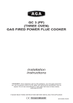
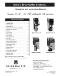
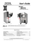
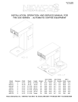
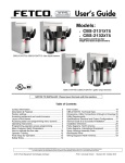
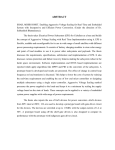
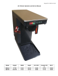
GRIND’N BREW COFFEE SYSTEM™
for Grind’n Brew - Single Bean, Dual Bean and Airpot Brewers
(Model -11, -21, -10, -20 Including H, HQ and E versions)
Operation and Instruction Manual
GRIND’N BREW KAFFEEMASCHINEN™
für Grind’n Brew - Kaffeemaschinen mit einem Bohnenfach, zwei Bohnenfächern und
für Maschinen mit Isolierkanne (Airpot) (Modell -11, -21, -10, -20 inklusive Modell H, HQ und E)
Bedienungsanleitung
SISTEMA PARA CAFÉ GRIND’N BREW™
para Grind’n Brew - Versiones simples con un compartimiento para granos, con dos compartimientos
para granos y con “Airpot” (envase térmico) (Modelos 11, 12, 10, 20 incluyendo las versiones H, HQ y E)
Manual de operación e instrucciones
SISTEMI GRIND’N BREW COFFEE SYSTEM™
per macchine per caffè Grind’n Brew a tramoggia unica o doppia di alimentazione chicchi ed a “Airpot”
(contenitore termico) (Modelli -11, -21, -10, -20 comprese le versioni H, HQ ed E)
Manuale d’uso
GRIND’N BREW™
Ligne de machines à café
pour les modèles Grind’n Brew à réservoir à grains unique, à réservoir à grains double
et à «airpot» (thermos) ( Modèles 11, 21, 10, 20, y compris les versions H, HQ et E )
Manuel opératoire
GRIND’N BREW COFFEE SYSTEMS™
Table des matières
I
Indice
Inhoudsopgave
E Award for exporting
Nederlands
Grindmaster Corporation
4003 Collins Lane
Louisville, Kentucky 40245 USA
(502) 425-4776
FAX : (502) 425-4664
www.grindmaster.com
NL
Waarschuwingsstickers ....................................2
Technische gegevens ......................................2
Installeren van het apparaat ............................3
Aansluiten op de waterleiding ..........................3
Elektrische aansluiting en inschakeling............4
Koffiezetten ......................................................4
Bedienen van het toetsenpaneel......................5
Instellen van porties koffie en water ................5
Timerinstellingen ..............................................5
Instellen van de koffiemolen ............................6
Reinigen en onderhoud ....................................6
Vervangen van de afschuifplaat ......................7
Vervangen van de elektromagnetische
waterklep ..........................................................7
Instellingen van het regelpaneel ......................8
Oplossen van problemen ............................9-10
Bedradingsschema ....................................11-12
Explosietekeningen ..................................13-16
Italiano
Etichette antinfortunistiche . . . . . . . . . . . . . . .2
Dati tecnici . . . . . . . . . . . . . . . . . . . . . . . . . . .2
Installazione . . . . . . . . . . . . . . . . . . . . . . . . . . .3
Allacciamento acqua . . . . . . . . . . . . . . . . . . . .3
Allacciamenti elettrici e procedura
di avviamento . . . . . . . . . . . . . . . . . . . . . . . . .4
Preparazione del caffè . . . . . . . . . . . . . . . . . . .4
Pulsantiera . . . . . . . . . . . . . . . . . . . . . . . . . . . .5
Dosaggio caffè e acqua . . . . . . . . . . . . . . . . . .5
Regolazioni timer . . . . . . . . . . . . . . . . . . . . . . .5
Regolazione del macinacaffè . . . . . . . . . . . . .6
Pulizia e manutenzione . . . . . . . . . . . . . . . . . .6
Sostituzione della piastra di macinazione . . . .7
Sostituzione dell’elettrovalvola per l’acqua . . .7
Impostazioni del quadro di comando . . . . . . . .8
Guida risoluzione problemi . . . . . . . . . . . . .9-10
Schema cablaggi . . . . . . . . . . . . . . . . . . .11-12
Viste esplose . . . . . . . . . . . . . . . . . . . . . .13-16
Índice
Rótulos de advertencia ....................................2
Datos técnicos ..................................................2
Instalación de la unidad ....................................3
Conexión del agua ............................................3
Procedimiento de conexión
eléctrica y puesta en marcha ............................4
Preparación ......................................................4
Uso del teclado ................................................5
Ajuste del peso de la caga de café y del agua 5
Ajuste de los temporizadores............................5
Ajuste del molido ..............................................6
Limpieza y mantenimiento ................................6
Reemplazo de la placa de cizallamiento ..........7
Reemplazo del solenoide de agua....................7
Ajustes del tablero de control............................8
Solución de problemas ................................9-10
Diagrama de cableado ..............................11-12
Vistas esquemáticas ..................................13-16
Français
© Grindmaster Corporation, 1998
Printed in the USA
E
Inhaltsverzeichnis
Espanol
F
Etiquettes d’avertissement ..............................2
Renseignements techniques ............................2
Installation de la machine ................................3
Branchement de l’eau ......................................3
Branchement électrique et procédure
de mise en service ..........................................4
Percolation........................................................4
Fonctions du bloc tactile ..................................5
Réglage des charges utiles et de la
quantité d’eau ....................................................5
Points de consigne de la minuterie ..................5
Réglage de la mouture ....................................6
Nettoyage et entretien ......................................6
Changement de la plaque de cisaillement ......7
Changement du solénoïde de l’eau ................7
Points de consigne de la plaquette
de commandes ........................................................8
Dépannage ..................................................9-10
Schéma de câblage ..................................11-12
Vues agrandies..........................................13-16
D
Warnschilder . . . . . . . . . . . . . . . . . . . . . . . . . .2
Technische Daten . . . . . . . . . . . . . . . . . . . . . .2
Installation . . . . . . . . . . . . . . . . . . . . . . . . . . . .3
Wasseranschluß . . . . . . . . . . . . . . . . . . . . . . .3
Elektrische Anschlüsse und Inbetriebnahme . .4
Aufbrühen . . . . . . . . . . . . . . . . . . . . . . . . . . . .4
Gebrauch der Schaltflächen . . . . . . . . . . . . . .5
Kaffeeportion und Wassermenge einstellen . .5
Timer einstellen . . . . . . . . . . . . . . . . . . . . . . . .5
Mahlstärke einstellen . . . . . . . . . . . . . . . . . . . .6
Reinigung und Wartung . . . . . . . . . . . . . . . . . .6
Abscherplatte auswechseln . . . . . . . . . . . . . . .7
Wassersolenoid auswechseln . . . . . . . . . . . . .7
Steuerung einstellen . . . . . . . . . . . . . . . . . . . .8
Fehlerbehebung . . . . . . . . . . . . . . . . . . . . .9-10
Schaltbild . . . . . . . . . . . . . . . . . . . . . . . . .11-12
Detailansichten . . . . . . . . . . . . . . . . . . . . .13-16
Deutsch
GB Table of Contents
Warning Labels . . . . . . . . . . . . . . . . . . . . . . . .2
Technical Data . . . . . . . . . . . . . . . . . . . . . . . . .2
Unit Installation . . . . . . . . . . . . . . . . . . . . . . . .3
Water Hook-up . . . . . . . . . . . . . . . . . . . . . . . . .3
Electrical Hook-up & Start-up Procedure . . . . .4
Brewing . . . . . . . . . . . . . . . . . . . . . . . . . . . . . .4
Operating the Touchpad . . . . . . . . . . . . . . . . .5
Setting Throw Weights and Water Portion . . .5
Timer Settings . . . . . . . . . . . . . . . . . . . . . . . . .5
Setting the Grind . . . . . . . . . . . . . . . . . . . . . . .6
Cleaning and Maintenance . . . . . . . . . . . . . . .6
Shear Plate Replacement . . . . . . . . . . . . . . . .7
Water Solenoid Replacement . . . . . . . . . . . . .7
Control Board Settings . . . . . . . . . . . . . . . . . .8
Trouble Shooting . . . . . . . . . . . . . . . . . . . .9-10
Wiring Diagram . . . . . . . . . . . . . . . . . . . . .11-12
Exploded Views . . . . . . . . . . . . . . . . . . . .13-16
~
Handleiding
English
voor Grind’n Brew koffiezetapparaten met één of twee compartimenten voor koffiebonen
en koffiezetapparaten met airpot (Model -11, -21, -10, -20 inclusief H, HQ en E uitvoeringen)
0604 Form # BW-353-03
Part # 71333
WARNING LABELS
The following warning labels were on your grinderbrewer when it shipped from the factory. They should remain
on your grinderbrewer in good, readable condition at all times. If one of your labels is missing or damaged,
order a replacement label immediately.
Part# 71104
Located on outside back, grinderbrewer casing
Part # 61497
Located on front of grinderbrewer casing
WARNING
• USE ONLY ON A CIRCUIT THAT IS PROPERLY
PROTECTED AND CAPABLE OF THE RATED LOAD.
• ELECTRICALLY GROUND THE CHASSIS
• DO NOT DEFORM PLUG OR CORD
• FOLLOW NATIONAL AND LOCAL ELECTRICAL CODES
• WATER CONNECTIONS SHALL COMPLY WITH THE PLUMBING CODE OF
BOCA & THE FOOD SERVICE SANITATION MANUAL OF THE FDA
• DO NOT USE NEAR COMBUSTIBLES
• FAILURE TO COMPLY RISKS PERSONAL INJURY, DAMAGE TO
EQUIPMENT, FIRE OR SHOCK HAZARD
• READ THE ENTIRE OPERATING MANUAL INCLUDING THE LIMIT OF
WARRANTY AND LIABILITY BEFORE BUYING OR USING THIS PRODUCT
• ALWAYS UNPLUG UNIT FROM POWER SUPPLY BEFORE SERVICING
OPGELET! HETE VLOEISTOFFEN EN OPPERVLAKKEN
English
Technical Data - Export Models
MODEL
PART #
VOLTAGE
FREQUENCY
WATTS
CIRCUIT BREAKER
NO. OF HOPPERS
HOPPER CAPACITY/HOPPER
BREW CAPACITY
NO. OF WARMERS
10HE
70929
11HE
70913
20HE
70931
21HE
70915
230
50/60 Hz
3270
20
1
2,5 kg
1,9 L
230
50/60 Hz
3360
20
1
2,5 kg
1,9 L
1
230
50/60 Hz
3270
20
2
3 kg
1,9 L
230
50/60 Hz
3360
20
2
3 kg
1,9 L
1
x
x
x
x
x
x
x
x
x
x
x
x
x
x
x
x
x
x
x
x
23,5
61,6
*78,8
29 kg
36,3
23,5
61,6
66,7
29 kg
36,3
23,8
61,6
*95,25
36 kg
43,1
23,8
61,6
83,2
36 kg
43,1
FEATURES :
GRIND’N BREW
GRIND ONLY
BREW ONLY
HALF BREW
PAINTED CASING
STAINLESS CASING
OUTLET FOR WARMERS
DIMENSIONS :
WIDTH (cm)
DEPTH (cm)
HEIGHT (cm)
WEIGHT (kg)
SHIPPING WEIGHT (kg)
* BASED ON 5" LEG HEIGHT
** INCLUDING WATER INLET FITTING
Grind ’n Brew Coffee Systems
Page 2
Grind ‘n Brew Installation, Start-up, and Brewing Instructions: (Read Completely!)
Important: This brewer should be installed by a knowledgeable and experienced commercial
equipment installer.
Brewer Contents
Your brewer package should include the following:
1-Grinderbrewer (either single or dual bean)
1-Operation and Instruction Manual (this manual)
1-Hose to 1/4" flare fitting (part # 61237)
Tools Required for Installation
#2 Phillips screwdriver
9/16" Wrench
5/8" Wrench
(Or Crescent Wrench)
6" Level
Note: Other tools may be needed depending on the type of water supply tubing and location.
English
Unit Installation
1. Inspect unit to see if any damage occurred in shipment.
2. Position brewer on counter. Place on sturdy permanent counter top. (If you have an airpot brewer,
Install 4" plastic legs (included) to the bottom of brewer. Lean brewer towards side to expose screwholes underneath for legs. Adjust leg heights to suit the size airpots you will use.)
Important: Adjust feet to level brewer. With bubble level, check to see that the brewer is level on
countertop.
Water Hook-up (All Models):
Important: This equipment must be installed in compliance with applicable Federal, State, and/or Local
plumbing codes having jurisdiction.
1. The incoming water supply should have a shut-off valve connected in-line. The end should have a
female 1/4" flare fitting. Water supply should be a 1/4" I.D. dedicated line branched off a 1" or larger
supply line.
2. Prior to installing the brewer, flush out the water line by running approximately 1 gallon of water into
a pail. This will insure no sediment from a new installation can get in the brewer.
3. Make sure your source water is turned off. Connect the source water line’s 1/4" female flare fitting (1)
to the 1/4" male fitting on the hose connector (2).
4. Make sure Grind’n Brew is unplugged. Connect source water line to brewer with hose connector.
5. Turn source water valve on, sending water to the brewer. If there are any leaks, tighten connections
to stop leakage.
Figure A
Page 3
Grind ’n Brew Coffee Systems
Electrical Hook-up and Start-Up Procedure (All Models) (Do not plug in unit yet!)
Important: This equipment must be installed in compliance with applicable Federal, State, and/or
Local electrical codes having jurisdiction. Do not use extension cords. Make sure that
outlet brewer plugs into is grounded.
Important: Make sure “Main Power Switch” in back of unit is in “off” position before
plugging in brewer.
Important: Domestic Q models at 208/230V must have a 4 wire electrical connection. Circuit
must have 2 hots, 1 ground, and 1 neutral wire. Failure to install with 4 wire
connecion will void manufactures’ warranty. Grind’n Brews that are 208/230 volt
require a 20 amp circuit. Export “E” models must have a 3 wire electrical
connection. Circuit must have 2 hots, and 1 ground (no neutral).
1.
2.
3.
4.
Plug in brewer to electrical outlet. (Or run power to unit for hardwire applications)
Make sure brewbasket is inserted in brewrails.
Reach to the back of the brewer and press the white “main power switch” to the “on”
position. The front control lights will go on and you will hear water entering the brewer. The
tank will fill in 2-3 minutes from the moment you pressed the “main power switch” to “on”.
Now that the tank is full, it will take 10-15 minutes to heat the water to brewing temperature.
(Cut that time in half for the 230V “Q” models). Once the “ready” light is lit, you are ready to
brew.
Brewing
Important: Brewers are factory set for the correct grind and brew times for average situations. You
should not need to make adjustments in the field.
4.
5.
6.
7.
8.
Page 4
Make sure new paper filter is in the brewbasket and brewbasket is in place in brewer.
Place beans in hopper.
Choose to “Grind and Brew”:
Basic Models-Press switch to “Grind ’n Brew”
“H” Half batch models or all dual bean models-Press far right touchpad so “grind” and
“brew” lights are lit.
Choose Portion:
Basic models-no choice, only full batch.
“H” Half batch models or all dual bean models-choose full or half by pressing touchpad until
desired volume is lit.
Choose decaf or regular coffee (only applicable to dual bean Grind ’n Brews). Press left
touchpad. Arrow will either point left or right for “decaf” or “regular”.
Place decanter or airpot under brewbasket depending on model.
Press Start. You will see coffee bean level go down slightly. You will hear coffee grind.
Coffee automatically is ground and portioned and placed in brewbasket. Then ground coffee
is automatically brewed. The “ready” light will now blink signifying that grinding and brewing
is in process. This will take 3-4 minutes for a 1,7L - 1,9L pot. Portions are factory set. After
brewing a pot, the tank must reheat. Reheat times are 5 1/2-8 minutes for 120V brewers
and half that for 230V machines. Remember, the brewer will not function (although the
grinder will) until the “ready” light is on, indicating the water is hot enough to brew. A
flashing green light means brewer is reheating or there is a cycle in progress. Do not
remove brewbasket while flashing.
On models GNB-11(11Q)(10)(10Q), press rocker switch to “Grind Only” position when you
wish to grind coffee but not brew. This will allow you to grind coffee for other brewers in
use. For “H” half batch and dual bean models, use following instructions on operating the
touchpad.
English
1.
2.
3.
Grind ’n Brew Coffee Systems
(See Figure B)
Bean Selector
(Dual Bean Models Only)
Half or Full Pot
Grind only
Brew only
Grind and Brew Option
Figure B
(Dual Bean Model)
Important:
Figure C
(Single Bean Model)
English
Brewers are factory set for throw weight and water portion. Please check that installation is
correct before making adjustment. No adjustments should be necessary for normal installation.
Setting Throw Weights and Water Portion: (See Figure D)
Tools Required: #2 Phillips Screwdriver
1. Remove lower front access panel to expose digital timer. Refer to chart to
determine timer setting for the amount of coffee/water you wish to dispense.
2. Use the select button to toggle to the setting available on your unit.
3. Use the up and down buttons to make your adjustments to the settings,
then press the select button again to store your new settings. The display
will flash to indicate your settings have been stored. Scroll through settings
to confirm timer setting gives desired dispense volume.
a.) Brew a pot to confirm timesetting gives desired dispense volume.
b.) Record your new timer values on the customer settings chart
located on time face.
4. After a few seconds, the display will shut itself off. The access panel may
be re-installed.
Figure D
GRIND’N BREW Timer settings/ with new PDS Flow control valve
A standard 1,9L bottle Grind’n Brews
Single/Left Full Pot
Right Full Pot
Single/Left Half Pot
Right Full Pot
All Airpot Grind’n Brews
Setting
Approx
Setting
Approx
Setting
Approx
Setting
Approx
Single Bean
yeild
Dual Bean
yield
Single Bean
yeild
Dual Bean
yield
4.2 secs
2 oz./6ml
5.7 secs
2 oz./5.8ml
Single/Left Full Pot
4.5 secs
2.3 oz./7ml
6.2 secs
2.3 oz./7ml
-
-
5.7 secs
2 oz./5.8ml
Right Full Pot
-
-
6.2 secs
2.3 oz./7ml
2.4 secs
1.25 oz./4ml
3.0 secs
1.25 oz./3.6ml
Single/Left Half Pot
2.7 secs
1.4 oz./4ml
3.7 secs
1.4 oz./4ml
Right Full Pot
-
-
3.0 secs
1.25 oz./3.6ml
Full Pot
112-125 secs
62 fl oz./180ml
112-125 secs
62 fl oz./180ml
Half Pot
56-63 secs
31 fl oz./90ml
56-63 secs
31 fl oz./90ml
-
-
3.7 secs
1.4 oz./4ml
Full Pot
140-153 secs
72 fl oz./209ml
140-153 secs
72 fl oz./209ml
Half Pot
70-77 secs
36 fl oz./104ml
70-77 secs
36 fl oz./104ml
• Increase of 1 second to timer setting equates to an increase in fluid volume by 1/2 ounce/1.5ml.
• Decrease of 1 second to timer setting equates to a decrease in fluid volume by 1/2 ounce/1.5ml.
Page 5
Grind ’n Brew Coffee Systems
Setting Grind:
Tool Required: #2 Phillips screwdriver, 7/8"/2.2cm box wrench, large flat blade screwdriver
1. Remove front decal panel by removing screw on underside of panel.
2. Loosen adjusting screw lock nut by turning counter clockwise.
3. Turn slotted adjusting screw clockwise to make the grind coarser or
counter clockwise to make the grind finer. (See Figure E)
Generally, a 1/8 to 1/4 turn will provide desired adjustment.
4. After adjustment has been made, re-tighten adjusting screw lock nut.
5. Visually inspect grind adjustment with a small portion of coffee and
readjust if necessary.
6. Reinstall the front decal panel as it was removed.
REGULAR MAINTENANCE Note : Machine should not be cleaned with a
pressure sprayer. This could result in a
shock hazard.
Figure E
Daily Cleaning
Cabinet :
The outside of the machine can be cleaned with a damp cloth, a household dusting
spray or a stainless steel cleaner. Do not use an abrasive such as Scotchbrite or
Brillo pads. These may mar the finish.
Wipe the underside of the cabinet hood with a clean cloth. Be especially careful when
using soap or detergent around the sprayhead. Any soap left on the deflector may impart
an unpleasant taste to the first brews.
Weekly Cleaning
Slide Valve: The slide valve behind the spray
deflector under the cabinet hood should be
wiped off with a clean, dry cloth. Using the
finger tab (Figure F) open the slide valve.
Note: When the machine is not in use, the
finger tab will automatically activate every 30
minutes to keep clear.
Brew Basket, Airpots and Decanters: Use
commercial grade urn cleaner (as directed by
manufacturer) and rinse thoroughly.
Figure F
Page 6
Grind ’n Brew Coffee Systems
English
Warmers : The warmer plate is easy to clean and will maintain its appearance longer if cleaned
regularly. Coffee stains can be wiped off with a damp cloth. Use detergent or sanitizer
for heavy deposits, but refrain from using abrasives.
SHEAR PLATE REPLACEMENT
Tools Required: #2 Phillips Screwdriver, Large flat blade screwdriver
1. Unplug machine.
2. Remove front panel and hopper. To remove hopper, pull bean shut-off valve forward. This will shutoff the flow of coffee beans and allow you to lift it from the grind head.
3. Remove hopper cradle. There are 5 screws (2 in front and 3 across back)
holding the hopper cradle in place. Loosen screws and lift up hopper
cradle.
4. Remove spray head. First remove the spray deflector by spinning
Figure G
it clockwise. Second, pull the spray nozzle away from mounting
sheet.
5. Remove grind cap by loosening the 2 screws and rotating the
grind cap away from the screws.
6. Pull out the revolving burr and freedworm assembly. The
sweeps on the revolving burr must line up with the cut outs on
the grind head. (See Figure G).
7. Remove the shear cap and broken shear plate.
8. Slide the rotating burr onto the motor shaft, aligning up the sweeps with the
cutouts on the grind head. Rotate the burr so that the burr is held back into the
burr pocket by the sweeps on the grind head lip. Slide the drive coupler into place.
Rotate the slot on drive coupler with the feed worm. Insert a new shear plate.
Shear disc
9. Reassemble the remaining components in reverse order of disassembly.
plate
WATER SOLENOID VALVE (See Figure H)
English
Tools Required: #2 Phillips screwdriver, pliers, 1/4" sockets
Note: The water solenoid valve is accesible from the rear of the unit.
This water valve contains a flow washer which delivers a constant
water flow rate of 0.29 (1.1L) gallons per minute.
1.
2.
3.
4.
Unplug machine.
Remove two lower screws from access panel.
Pivot panel and pull away from machine.
Disconnect electrical connections and water line from water valve. The
water line is removed by sliding the sleeve on the elbow fitting and
pulling the hose out of the fitting.
5. Disassemble water valve and de-lime.
6. Reassemble in reverse order of disassembly.
Figure H
Page 7
Grind ’n Brew Coffee Systems
CONTROL BOARD SETTINGS
J1
J2
Jumper should remain on pin 1 & 2
Jumper Controls
-No pin connected with jumper-No minimum brewing temperature
-Jumper connecting 2 & 3 - Low temperature no brew. The brewing cycle with wait
until
temperature of water is ready before continuing
(factory setting)
-Jumper connecting 1 & 2 - Disables thermister, unit must use a thermostat to operate
properly (not normally used)
English
Number 1 pins
Jumper J1
Jumper J2
Page 8
Grind ’n Brew Coffee Systems
185ÞF/85ÞC
oz (100 grams) of coffee.
English
Page 9
Grind ’n Brew Coffee Systems
English
For additional questions please contact your local Grindmaster distributor and have model
and serial number ready so that information can be given.
Prior authorization must be obtained from Grindmaster’s Technical Services Department for
all warranty claims.
Page 10
Grind ’n Brew Coffee Systems
English
Page 11
Grind ’n Brew Coffee Systems
English
Page 12
Grind ’n Brew Coffee Systems
English
Page 13
Grind ’n Brew Coffee Systems
English
DESCRIPTION
RIGHT BASKET ARM
LEFT BASKET ARM
BRACKET, BASKET ARM
CENTER SPRING
RIGHT BASKET ARM SPRING
LEFT BASKET ARM SPRING
SHOULDER BOLT, 5/16" X 5/8" SS
SPACER, 5/8" X 1/4"
NUT, ESNA 1/4-20 SS
SWITCH, SNAP ACTION
SCREW, 4-40 X 5/8"
NUT, 4-40
BELLOW
WASHER, 1/4" ID SAE SS
Page 14
Grind ’n Brew Coffee Systems
English
Page 15
Grind ’n Brew Coffee Systems
DESCRIPTION
HOPPER CRADLE ASSEMBLY
FLANGED SLEEVE, .183" OD SS
SCREW, 6-32 X 1/2" PH RD HD SS
HOPPER LID ASSEMBLY
HOPPER ASSEMBLY
WINGNUT, ESNA 1/4-20
BOLT, CARRIAGE 1/4-20 X 1/2" SS
BEAN SHUTOFF
HOPPER GASKET
SCREW, 8-32 X 1/2" PH TR SS
FRONT PANEL ASSEMBLY
NUT, ESNA 6-32
SPRING, SHUTTER
NUT, ESNA 1/4-20 SS
BRACKET, SHUTOFF
SHOULDER BOLT, 5/16" X 5/8"
English
DESCRIPTION
HOPPER CRADLE ASSEMBLY
HOPPER LID ASSEMBLY
NYLON SCREW, 8-32 X 1/2 SL BD
NYLON NUT, 8-32 LOCK
HOPPER PARTITION
DUAL BEAN HOPPER ASSEMBLY
SHUTOFF VALVE
CENTER SPRING
SHUTOFF VALVE BRACKET
NUT, 1/4-20 ESNA
SHOULDER BOLT, 5/16" X 5/8"
NUT, 6-32 ESNA
FRONT PANEL ASSEMBLY
PORTIONER, UPPER HALF
AUGER DRIVE SPRING
SCREW, 8-32 X 3/8 PH FL
SCREW, 6-32 X 1/2 PH PN BLACK
PORTIONER COVER PLATE
120 VOLT AUGER MOTOR
240 VOLT AUGER MOTOR
AUGER MOTOR BRACKET
TINNERMAN, 8-32 S.S.
AUGER DRIVE FEEDER
RIVNUT, 8-32 SECOND GRIP
AUGER MOTOR WIRE HARNESS
SCREW, 8-32 X 1/2 PH PN TYPE F
PORTIONER, LOWER HALF
PORTIONER GASKET
8-32 ESNA NUT
8-32 X 1/2 PH PN SS SCREW
1/4-20 WING NUT
BRACKET W/ 1/4-20 STUD
Page 16
Grind ’n Brew Coffee Systems