1
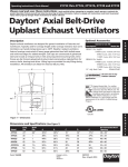
READ AND SAVE THESE INSTRUCTIONS
Models RBU/RBUMO/RDU
Upblast Propeller Roof Fans
Belt Drive and Direct Drive
GREENHECK
®
PN 455700
P.O. BOX 410 SCHOFIELD, WISCONSIN 54476-0410
PH. 715-359-6171
www.greenheck.com
Installation, Operation and Maintenance Manual
Greenheck Model RBU, RBUMO and RDU fans are thoroughly inspected and test run at
the factory, however damage may occur during handling and shipping. Consequently, it
is important that the unit be carefully inspected for visible and concealed damage before
beginning installation. Report any damage to the shipper immediately. In
addition, assure all accessory items are accounted for.
INSTALLATION
LIFTING
Attach a suitable chain or strap to the four windband mounting brackets,
which are designed to be used as lifting lugs (Fig. 1). Do not lift the
fan by the motor, belt
tube, damper frame,
Fig. 1
windband or
accessories.
Carefully lift the fan to
the roof curb and install
fasteners in all holes
provided in the unit
base. The windband
does not need to be
removed for the lifting
operation.
Lifting Lug
SERVICE ACCESS
MOTOR OUT OF AIRSTREAM
Model RBUMO simplifies inspection and servicing with the “motor out
of the airstream” design. A removable motor cover enables quick and
easy access to the motor, belt, and drives from the roof deck (Fig. 2).
Servicing of propeller and bearings can easily be accomplished by
removing the fan panel/windband assembly from the fan base.
REMOVABLE WINDBAND
By removing the bolts from the four windband mounting brackets, the
windband can be removed. With the windband removed, access to the
fan can be gained through the butterfly dampers. This service feature
applies to models RBU, RBUMO and RDU (Fig. 1).
Fig. 2
1
ELECTRICAL CONNECTIONS
Before electrical connections are made, the supply voltage, phase and ampere capacity must be checked for compatibility
with the fan motor. In addition, the supply wiring must be properly fused and conform to local and national electrical codes.
The supply wires are then connected to an optional safety disconnect switch (if supplied) or wired directly to the motor.
For belt drive units in Emergency Smoke Removal installations, the electrical supply must be kept out of the airstream.
They may also require an isolated power supply so that if power is cut to the building in the event of a fire, the fan will
continue to operate. Check the local and national electrical codes for emergency smoke removal fans.
** WARNING **
Disconnect and secure to the “off” position all electrical power to the fan prior to inspection or
service.
Caution must be used when working around the fusible link damper lifters. They may release
the dampers unexpectedly.
Models RBU, RBUMO and RDU may have fusible link damper lifters and all models RBUMO with
high temperature options have fusible link damper lifters under spring tension. RBUMO fans
UL listed as “Power ventilators for smoke control systems” in sizes 42, 48, 54 and 60 have
extra heavy duty fusible link damper lifters under high spring tension that, for safety reasons,
must be pinned to prevent accidental release. See Fig. 3 below for details on how to secure the
lifter arms.
FAILURE TO COMPLY WITH THESE SAFETY PRECAUTIONS MAY
RESULT IN SERIOUS INJURY OR DEATH!
For Models RBUMO with high temperature option - UL Listed
WARNING !
These fans have extra heavy duty fusible link
damper lifters under very high spring tension
that must be pinned so they can not be
accidentally tripped when servicing the fan. The
fusible link damper lifters are located under the
butterfly damper blades. Fig. A, shows where the
safety pin MUST be placed when the fan is being
serviced. Fig. B, shows where the safety pin is placed
for storage when the fan is in service. Fan sizes 20,
24, 30 and 36 also have fusible link damper lifters, but
they do not have the ability to be pinned when
servicing due to differences in lifter designs. In either
case, extreme care must be taken when working
around the damper lifter assemblies or serious
bodily injury or death may result.
Fig. 3
Safety pins installed
IMPORTANT
Fig. A
Electrical - This equipment must be
installed with remote overload
protection having adequate rating
as to voltage, frequency,
horsepower and full load current per
phase. Where connected to a circuit
protected by fuses, use time delay
fuses. For supply connection use
wires rated for at least 90°C (194°F)
Fig. B
Safety Pin
Storage
Locations
to prevent closure
while servicing fan
Installation - When connecting
electrical power to this fan, do not
restrict motor movement. Motor
must have sufficient movement for
possible future belt or wheel
adjustment.
00453547
Models RBUMO with High Temperature Option - UL
Listed will bear the label shown at right. For fan sizes
42, 48, 54 and 60 Figs. A and B apply.
2
C
UL
R
US LISTED
VENTILATOR
FOR
SMOKE
CONTROL
SYSTEMS.
76Y9
PRESTARTING CHECKS
Check all fasteners and set screws for tightness. This is especially important for
bearing set screws.
The propeller should rotate freely and not rub on the fan panel venturi. Rotation
direction of the propeller should be checked by momentarily turning the unit on.
Rotation should be in the same direction as the rotation decal affixed to the unit
or as shown in Fig. 4. For 3-phase installations, fan rotation can be reversed by simply
interchanging any two of the three electrical leads. For single phase installations
follow the wiring diagram located on the motor.
Airflow
Airflow
Rotation
Rotation
FOR BELT DRIVE FANS
The adjustable motor pulley is preset at the factory for the specified fan RPM. Fan
speed can be increased by closing or decreased by opening the adjustable pulley.
Two or three groove variable pitch pulleys must be adjusted an equal number of turns
open. Any increase in fan speed represents a substantial increase in horsepower
required from the motor. Always check motor load amperage and compare to name
plate rating when changing fan speed.
Fig. 4
ROUTINE MAINTENANCE
WARNING
DISCONNECT AND SECURE TO THE “OFF” POSITION ALL ELECTRICAL POWER TO THE FAN
PRIOR TO INSPECTION OR SERVICING. FAILURE TO COMPLY WITH THIS SAFETY PRECAUTION
COULD RESULT IN SERIOUS INJURY OR DEATH.
Once the fan has been put into operation, a periodic maintenance program should be set up to preserve the reliability
and performance of the fan. Items to be included in this program are:
•
•
•
•
•
•
BELTS
BEARINGS
FASTENERS
SET SCREWS
LUBRICATION
REMOVAL OF DUST/DIRT
Deflection =
Belt Span
Fig. 5
BELTS
Belt Span
64
Premature belt failures are frequently caused by improper belt tension
(either too tight or too loose) or misaligned pulleys. The proper tension for
operating a V-belt is the lowest tension at which the belts will not slip at
peak load conditions. For initial tensioning, the proper belt deflection half
way between pulley centers is 1/64" for each inch of belt span. For
example, if the belt span is 64 inches, the belt deflection should be one
inch using moderate thumb pressure at midpoint of the drive (Fig. 5).
Check belt tension two times during the first 24 hours of operation and
periodically thereafter. To adjust belt tension, simply loosen four fasteners
(two on each side of the motor plate) and slide the motor plate away from
the fan shaft until proper belt tension is attained. On some fans, fasteners
attaching the motor to the motor plate must be loosened in order to adjust
the belt.
It is very important that the drive pulleys remain in proper alignment after
adjustments are made. Misalignment of pulleys will result in premature
belt wear, noise, vibration and power loss. See Fig. 6.
WRONG
WRONG
WRONG
CORRECT
Fig. 6
BEARINGS (For belt drive fans only)
Bearings are the most critical moving part of the fan and should be inspected at periodic intervals. Locking collars
and set screws, in addition to fasteners attaching the bearings to the bearing plate, must be checked for tightness. In a
clean environment and temperatures above 32°F./below 200° F., fan shaft bearings with grease fittings
should be lubricated semi-annually using a high quality lithium based grease. If unusual environmental conditions exist
temperatures below 32°F./above 200°F., moisture or contaminants, more frequent lubrication is required.
With the unit running, add grease very slowly with a manual grease gun until a slight bead of grease forms at
the seal. Be careful not to unseat the seal by over lubricating or using excessive pressure. Bearings without grease fittings are
lubricated for life.
3
FASTENERS AND SET SCREWS
Any fan vibration has a tendency to loosen mechanical fasteners. A periodic inspection should include checking all
fasteners and set screws for tightness. Particular attention should be paid to set screws attaching the propeller to the
shaft and the shaft to the bearings. Loose bearing set screws will lead to premature failure of the fan shaft.
LUBRICATION
Refer to the paragraph on bearings for bearing lubrication. Many fractional horsepower motors installed on the smaller fans are
lubricated for life and require no further attention. Motors equipped with oil holes should be oiled in accordance with the
manufacturer’s instructions printed on the motor. Use a high grade SAE 20 machine oil and use caution not to over lubricate.
Motors supplied with grease fittings should be greased according to directions printed on the motor.
REMOVAL OF DUST AND DIRT
Dirt clogs cooling openings on the motor housing, contaminates bearing lubricant and collects on propeller blades
causing severe imbalance if left unchecked. The exterior surface of the motor, fan panel and entire propeller should be
thoroughly cleaned periodically. Use caution and do not allow water or solvents to enter the motor or bearings. Under no
circumstances should motors or bearings be sprayed with steam or water.
DAMPER INSPECTION AND SERVICE
CAUTION: Butterfly dampers on units supplied with optional spring lifter bars are under spring tension and will open
forcefully if the fusible link is released. Butterfly dampers should be inspected for proper operation at each service interval.
Check for freedom of movement and general condition of the damper blades and hinge rods.
Belt Drive Fans Parts List
Direct Drive Fans Parts List
9
1
1
3
2
8
2
4
5
4
5
3
7
1.
2.
3.
4.
5.
6.
7.
8.
9.
10.
11.
6
10
1.
2.
3.
4.
5.
Fan Panel
Propeller
Drive Frame Channel (2)
Motor Plate
Motor
Motor Pulley
Shaft Pulley
Fan Shaft
Bearings (2)
Belt
Bearing Plate (Level 3 fans only - not shown)
Copyright © 2000 Greenheck Fan Corp.
4
Fan Panel
Propeller
Drive Frame Channel (2)
Motor Plate
Motor
IOM RBU/RBUMO/RDU
Rev. 2 December 2000