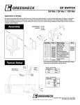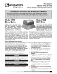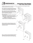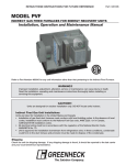
1
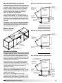
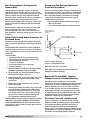
PN 471555
Centrifugal Laboratory Exhaust
®
Installation, Operation and Maintenance Manual
Please read and save these instructions. Read carefully before attempting to assemble, install, operate or maintain the
product described. Protect yourself and others by observing all safety information. Failure to comply with instructions
could result in personal injury and/or property damage! Retain instructions for future reference.
Vektor-CD
Direct or Belt Drive
The Vektor-CD fan is a side inlet centrifugal blower
with a high plume dilution nozzle designed for
laboratory exhaust systems. Available in either direct
or belt drive configurations, the Vektor-CD is capable
of up to 14 inches wg of static pressure and 100,000
cfm and can be constructed to AMCA spark B or
C specifications. All fans are AMCA 210 and 260
certified for flows as well as AMCA 300 for sound. The
Vektor-CD is available in 15 sizes ranging from 12 to
66 inch wheels. Each fan has a permanently affixed
manufacturer’s engraved metal nameplate containing
the model number and individual serial number.
by
General Safety Information
Only qualified personnel should install this fan system.
Personnel should have a clear understanding of these
instructions and should be aware of general safety
precautions. Improper installation can result in electric
shock, possible injury due to coming in contact with
moving parts, as well as other potential hazards.
Other considerations may be required if high winds
or seismic activity are present. If more information
is needed, contact a licensed professional engineer
before moving forward.
DANGER
Always disconnect power before working on or
near a fan. Lock and tag the disconnect switch or
breaker to prevent accidental power up.
CAUTION
When servicing the fan, motor may be hot enough
to cause pain or injury. Allow motor to cool before
servicing.
CAUTION
Precaution should be taken in explosive
atmospheres.
Vektor-CD Centrifugal Laboratory Exhaust
1. Follow all local electrical and safety codes, as well
as the National Electrical Code (NEC), the National
Fire Protection Agency (NFPA), where applicable.
Follow the Canadian Electric Code (CEC) in
Canada.
2. The rotation of the wheel is critical. It must be free
to rotate without striking or rubbing any stationary
objects.
3. Motor must be securely and adequately grounded.
4. Do not spin fan wheel faster than maximum
cataloged fan rpm. Adjustments to fan speed
significantly effects motor load. If the fan RPM is
changed, the motor current should be checked to
make sure it is not exceeding the motor nameplate
amps.
5. Do not allow the power cable to kink or come in
contact with oil, grease, hot surfaces or chemicals.
Replace cord immediately if damaged.
6. Verify that the power source is compatible with the
equipment.
7. Never open access doors to a duct while the fan is
running.
Receiving
Upon receiving the product, check to make sure
all items are accounted for by referencing the bill
of lading to ensure all items were received. Inspect
each crate for shipping damage before accepting
delivery. Notify the carrier if any damage is noticed.
The carrier will make notification on the delivery
receipt acknowledging any damage to the product.
All damage should be noted on all the copies of the
bill of lading which is countersigned by the delivering
carrier. A Carrier Inspection Report should be filled out
by the carrier upon arrival and the Traffic Department.
If damaged upon arrival, file claim with carrier. Any
physical damage to the unit after acceptance is not
the responsibility of Greenheck Fan Corporation.
Unpacking
Verify that all required parts and the correct quantity
of each item have been received, including accessory
kit containing flex connector, gasketing, etc. If any
items are missing report shortages to your local
representative to arrange for obtaining missing
parts. Sometimes it is not possible that all items
for the unit be shipped together due to availability
of transportation and truck space. Confirmation of
shipment(s) must be limited to only items on the bill of
lading.
Handling
Fans are to be rigged and moved by the lifting
brackets provided or by the skid when a forklift is
used. Location of brackets varies by model and
size. Handle each piece in such a manner as to keep
from scratching or chipping the coating. Damaged
finish may reduce ability of fan to resist corrosion.
See coating repair section of this manual for details
involving touch-up of damaged surfaces.
Fans should never be lifted by the shaft, fan housing,
motor, belt guard, weatherhood, windband or other
accessories.
Storage
Fans are protected against damage during shipment. If
the unit cannot be installed and operated immediately,
precautions need to be taken to prevent deterioration
of the unit during storage. The user assumes
responsibility of the fan and accessories while in
storage. The manufacturer will not be responsible
for damage during storage. These suggestions are
provided solely as a convenience to the user.
INDOOR
The ideal environment for the storage of fans and
accessories is indoors, above grade, in a low humidity
atmosphere which is sealed to prevent the entry of
blowing dust, rain, or snow. Temperatures should
be evenly maintained between 30°F (-1°C) and
110°F (43°C) (wide temperature swings may cause
condensation and “sweating” of metal parts). All
accessories must be stored indoors in a clean, dry
atmosphere.
Vektor-CD Centrifugal Laboratory Exhaust
Remove any accumulations of dirt, water, ice or snow
and wipe dry before moving to indoor storage. To
avoid “sweating” of metal parts allow cold parts to
reach room temperature. To dry parts and packages
use a portable electric heater to get rid of any
moisture build up. Leave coverings loose to permit air
circulation and to allow for periodic inspection.
The unit should be stored at least 3½ in. (89 mm) off
the floor on wooden blocks covered with moisture
proof paper or polyethylene sheathing. Aisles between
parts and along all walls should be provided to permit
air circulation and space for inspection.
OUTDOOR
Fans designed for outdoor applications may be stored
outdoors, if absolutely necessary. Roads or aisles for
portable cranes and hauling equipment are needed.
The fan should be placed on a level surface to prevent
water from leaking into the fan. The fan should be
elevated on an adequate number of wooden blocks so
that it is above water and snow levels and has enough
blocking to prevent it from settling into soft ground.
Locate parts far enough apart to permit air circulation,
sunlight, and space for periodic inspection. To
minimize water accumulation, place all fan parts on
blocking supports so that rain water will run off.
Do not cover parts with plastic film or tarps as these
cause condensation of moisture from the air passing
through heating and cooling cycles.
Fan wheels should be blocked to prevent spinning
caused by strong winds.
Inspection and Maintenance during
Storage
While in storage, inspect fans once per month. Keep a
record of inspection and maintenance performed; see
page 15.
If moisture or dirt accumulations are found on parts,
the source should be located and eliminated. At each
inspection, rotate the wheel by hand ten to fifteen
revolutions to distribute lubricant on motor and
bearings. If paint deterioration begins, consideration
should be given to touch-up or repainting. Fans with
special coatings may require special techniques for
touch-up or repair.
Machined parts coated with rust preventive should
be restored to good condition promptly if signs of
rust occur. Immediately remove the original rust
preventive coating with petroleum solvent and clean
with lint-free cloths. Polish any remaining rust from
surface with crocus cloth or fine emery paper and oil.
Do not destroy the continuity of the surfaces. Wipe
clean thoroughly with Tectyl® 506 (Ashland Inc.) or
the equivalent. For hard to reach internal surfaces or
for occasional use, consider using Tectyl® 511M Rust
Preventive or WD-40® or the equivalent.
®
REMOVING FROM STORAGE
Vektor-CD Arrangements
As fans are removed from storage to be installed
in their final location, they should be protected and
maintained in a similar fashion, until the fan equipment
goes into operation.
Prior to assembly and installation of the Vektor fan
and system components, inspect the fan assembly to
make sure it is in working order.
Vektor-CD
Single Fan System
Vektor-CD
Opposed Fan System
Vektor-CD
Dual Fan System
Vektor-CD
Triple Fan System
1. Check all fasteners, set screws on the fan, wheel,
bearings, drive, motor base and accessories for
tightness.
2. Rotate the fan wheel(s) by hand and assure
no parts are rubbing. Access to the wheel is
obtained through a bolted panel located on the
side of the fan housing.
3. Ensure proper wheel settings for radial gap and
alignment. Refer to page 13.
Installation
Installations with inlet or discharge configurations that
deviate from this standard may result in reduced fan
performance. Restricted or unstable flow at the fan
inlet can cause pre-rotation of incoming air or uneven
loading of the fan wheel yielding large system losses
and increased sound levels.
System Identification Tags
Vektor fan systems may arrive in component pieces
due to shipping restrictions. Individual components
of a system have matching identification tags
which should be used to identify and assemble the
complete system.
Assembling systems
with different
identification tags
can cause reductions
in the fan(s)
performance.
Rigging / Assembly Instructions
1. Use standard lifting and rigging practices.
2. All lifting lugs on each component must be utilized
at the same time.
3. Plenum, blower, and windband are to be kept level
during installation.
Chains
Spreader Bar
Chains
Lifting
Lugs
Lifting
Lugs
Standard Fan Configurations
The following illustration identifies a typcial
configuration of the Vektor-CD system. Greenheck
also supplies custom configurations. Your system
may not be depicted in the drawing shown. Refer to
submittal drawing.
WINDBAND
Roof Curb / Structural Support
FLEX CONNECTOR
ISOLATION
DAMPER
PLENUM
NOZZLE
FH
Bypass Air
Plenum
Gasketing
FAN
FL
FW
CURB SQR
PRIMARY INLET
OPTIONAL
ROOF CURB
ISOLATOR
®
Vektor-CD Centrifugal Laboratory Exhaust
Vektor-CD Centrifugal Laboratory Exhaust
®
Curb Installations
Bases—Foundation and Isolation
Greenheck supplies gasketing material for all multisection curbs and/or plenums. Install gasketing prior
to bolting split curbs and or plenums together.
Critical to every fan installation is a strong, level
foundation. A reinforced poured concrete pad with
a structural steel base or inertia base provides an
excellent foundation. Structural bases must be sturdy
enough, with welded construction, to prevent flexing
and vibration.
NOTE: Steel, concrete or wood support is per
structural engineer and in accordance with load
requirements and applicable building codes.
Structural Steel
Greenheck Roof Curb
for Vektor Systems
Continuous Weld or Stitch Weld
6 in. minimum stitch weld x 3-1/4 in. spacing
Minimum 6 in. weld on each corner.
(hardware by others)
Steel structural support
(by others)
To eliminate vibration and noise from being transferred
to the building, vibration isolators should be used.
The fan is mounted directly on the isolation base and
must be supported for the entire length of the fan base
angle (Refer to the installation manual for structural
bases if the base was supplied by Greenheck).
Isolators are installed between the isolation base and
the foundation.
After the fan, isolation base and isolators are installed,
the entire assembly must be leveled. Position the level
on the isolation base, not the fan shaft, for proper
leveling. Additionally, the motor and fan shafts must
be level and parallel relative to each other for proper
alignment.
NOTE: Steel,Deck
concrete or wood roof support is per structural engineer and
Concrete
in accordance with load requirements and applicable building codes.
Greenheck Roof Curb
for Vektor Systems
Install 1/2 in. bolt
5-1/2 in. maximum bolt spacing
4 in. maximum spacing from curb corners
(hardware by others)
Concrete structural support
(by others)
NOTE: Steel, concrete or wood roof support is per structural engineer and
Wood Deck in accordance with load requirements and applicable building codes.
Greenheck Roof Curb
for Vektor Systems
Install 1/2 in. lag or thru-bolt
(as determined by structural engineer)
with 1 in. washer in each hole shown above
(hardware by others)
Wooden structural support
(by others)
Vektor-CD Centrifugal Laboratory Exhaust
®
Riser Installation
Plenum Assembly
Check curb or structural supports for levelness. Both
must be level to ensure proper drainage from plenum
and fan(s).
Note: Gasketing material (shipped with fan) should
be placed on the top edge of already installed roof
curb prior to placing the plenum or individual plenum
sections on the curb.
Lab Exhaust Riser
If the plenum is shipped disassembled, the plenum
sections can be assembled together into one single
piece before lifting onto the roof and then fitted on
the roof curb / support structure, or each section can
be placed on individually. The method used would be
dependent on the lifting capacity for the equipment
on-site. If moving each piece separately onto the
roof curb or support structure, each section should
be joined to its mating part before moving another
section into place.
Riser duct(s) run up through the curb and are
flanged over the curb. (by contractor)
Roof Curb—anchor curb to roof
deck structure in accordance with
project construction documents
and local codes.
For a 1x1 system there is only a single plenum section
and no multiple plenum assembly would be required.
Determine the placement of the plenum
sections relative to each other
(Multiple Fan Systems)
Plenum Isometric View
When looking at the individual section one will notice
that each plenum section is missing at least one
side panel. These areas are the locations where the
sections are to be joined together. If you have two
plenum sections, then each one would be missing a
side panel. If you have a three-fan system, there are
three plenum sections. The two end plenum sections
would each be missing one side panel and the middle
section would not have panels on two sides. Please
refer to the submittal drawing for the orientation of
any Bypass Air Plenum (BAP) dampers or air inlet
locations.
Putting the plenum together
After identifying the plenum sections arrangement
order, one of the two mating sections has weld nuts
on the inside of the plenum. The assembly hardware
(stainless steel bolts) required to join the sections
is located here for shipping purposes. These bolts
should be removed and set-aside prior to placing the
mating sections together. The bolts are located every
6 to 10 inches to provide the best seal between the
mating sections.
For side inlet fans, remove panel at end of plenum.
This opening is the designed connection spot for user
connected ductwork from building.
Before moving the sections into position, gasketing
must be installed to seal the plenum sections against
leakage. This silicone gasketing is supplied with
the fans and only needs to be applied to one of the
two mating plenum sections. The bands or strips of
gasketing should be attached around the perimeter of
the joining face and with an additional strip making a
triangular area in each corner.
After the gasketing has been attached and the
hardware has been removed, place the two mating
sections together. The stainless steel bolts, which
were set aside earlier, are now run first through the
holes of the plenum section without the weld nuts and
tighten into the weld nuts on the other plenum section.
®
Vektor-CD Centrifugal Laboratory Exhaust
Plenum Assembly continued
An additional side (or access) panel may need to be
removed in order to gain access to the inside of the
plenum assembly. The bolts should be tightened in
an even and consistent manner as to pull the two
sections together and compress the gasketing.
Plenum and Curb
toPLENUM,
Structural
FAN,
AND Steel
CURB TO STRUCTURAL STEEL
⁄16 in. bolt
(typical)
(by Greenheck)
5
Weatherhood
with birdscreen
(optional)
Bypass Air
Plenum
After the plenum is assembled
Use all provided hardware to tighten and join the
mating sections together. Any side panels removed
to gain access to the interior of the plenum should be
reattached. The assembled plenum has holes in the
curb cap to fasten the plenum to the already installed
roof curb.
⁄16 in. silicone gasket
(by Greenheck)
3
⁄8 in. bolt
(typical)
(by Greenheck)
3
Fiberglass
Insulation
Bolt or weld in field
(by others)
The plenum is now ready to have gasketing placed in
the mounting location between the plenum and the
fan. After the gasketing has been attached the fans
can be lifted and set into place.
FAN, PLENUM, AND CURB Modular Plenum
STRUCTURAL STEEL
Isometric TO
View
Roof Curb
Structural Support
(by others)
FAN, PLENUM AND CURB TO ROOF DECK
PLENUM
(NO CURB)
PlenumFAN
(noAND
Curb)
to Channel
Base
TO CHANNEL BASE
⁄16 in. bolt
5
FAN, PLENUM, AND CURB(typical)
TO STRUCTURAL STEEL (by Greenheck)
Lifting Lugs
Weatherhood
with birdscreen
(optional)
Bypass Air
Plenum
⁄16 in. silicone gasket
(by Greenheck)
3
Drain hole
1 in. coupling
Bolted and gasketed
access panels
Field drilled & bolted
(by others)
Structural Support
(by others)
FAN, PLENUM AND CURB -
Plenum Installation
TO ROOF DECK
The figures depicted illustrate three common methods
used to install Vektor-CD bypass plenums. Methods
used to attach a Vektor unit are dependent on local
codes, roof construction design and roof construction
materials. Consult an architect or structural engineer
for proper means of attachment.
FAN AND CURB (NO PLENUM) TO ROOF DECK
Fan, Plenum, and
Curb
to Roof
DeckFAN,
PLENUM
AND CURB
TO ROOF DECK
⁄16 in. self-tapping screws
(by Greenheck)
5
Place 1/2 inch thick x 1/2 inch wide silicone gasket
around the perimeter of top edge of curb, adhesive
side down (gasket provided in Vektor-CD hardware kit).
Weatherhood
with birdscreen
(optional)
To align holes properly, the plenum needs to be
centered on the curb.
When holes are provided in the curb, install 316
stainless steel screws (provided) in all holes. Use antiseize gel (provided) to prevent galling / welding of all
stainless steel fasteners.
When holes are not provided in the curb (non
Greenheck curb): Drill 0.28 in. diameter holes in curb
using bypass air plenum holes as a template. Install
5/16 in. self-tapping screws (provided) in all the holes.
Vektor-CD Centrifugal Laboratory Exhaust
Bypass Air
Plenum
⁄16 in. silicone gasket
(by Greenheck)
3
⁄8 in. bolt
(typical)
(by Greenheck)
3
Fiberglass
Insulation
Roof Curb
Bolt or weld in field
(by others)
Roof Line
Exhaust Duct
(by others)
(Roofing felt
& material
by others)
®
Fan Installation
Fan Housing Installation
Lines of attachment
are to be lifted in the
vertical direction to
prevent damage.
Spreader bars
are recommended.
Lifting lugs located on the
four corners of the base
Windband Installation
Using the windband
Four (4) lifting
lifting lugs, place
lugs located
windband over blower
at top of
discharge, aligning
windband
windband support
bracket holes with
bolt holes in blower Four (4) lifting
lugs located
housing. Attach
at top of
windband to blower windband
discharge using 316
stainless steel bolts
(provided) through support brackets welded to the
inside of the windband. Use anti-seize gel (provided)
to prevent galling / welding of all stainless steel
fasteners.
If the windband is shipped attached to the fan housing
or if the windband is secured to the fan housing
Lifting lugs located at top
prior to mounting to the plenum, the fan / windband
of bypass air plenum
Bypass Air Plenum Installation
assembly should be lifted by the lifting lugs located
Span determines the number of lifting lugs to be used
** Greenheck
strongly
theassembly
use of guy wires
on any system
on the
fan housing.
Dorecommends
not lift this
by the
incorporates
of a stack extension
and fan
the subsequent
during installation:
liftingthat
lugs
located the
on usage
the windband.
Connect
guy wires are to be designed and installed by others.
to plenum
using Excelon™ flex connector found in the
Lifting lugs located at top
Vektor-CD hardware kit.
Span
S
of bypass air plenum
Fan Stack Installation
**Guy wire attachments
Span
No. of Lifting Lugs
Lines of attachment
Minimum
of be
4 lifting
are to
lifted lugs
in the
vertical
to
Minimum
of 6direction
lifting lugs
prevent damage.
Minimum
of 8 lifting
Spreader
bars lugs
are recommended.
12 inches or less
12 to 18 inches
Stack Extension
18 inches or greater
of attachment
Guy Wire Lines
Locations
Fan Assembly
are to be lifted in the
vertical direction to
prevent damage.
Spreader bars
are recommended.
Lifting lugs loca
four corners of t
If fan requires a stack or stack extension, install on
fan before installing nozzle and windband. Place
gasketing between any sections, blower housing and
initial stack. Use lifting lugs to position each piece
into place. Attach stack or stack extension to blower
housing using 316 stainless steel bolts (provided)
through flanges aligning bolt patterns. Use antiseize gel (provided) to prevent galling/welding of all
stainless steel fasteners.
Greenheck strongly recommends the use of guy
wires on any system that incorporates the usage
of a stack extension including inline attenuators.
Subsequent guy wires are to be designed and
installed by others.
®
Lifting lugs located on the
base
1-1/4 inch
typical
fourthru-hole
corners
of the
NOTE: Guy wires to be supplied by others. Fastening to
building structure to be provided and engineered by others.
If your fan requires stack extensions, the use of guy
wires is recommended. See drawing for guy wire
connection locations.
Note: Keep 36 inches minimum spacing around unit
to provide adequate clearance for servicing or
repairing unit.
Vektor-CD Centrifugal Laboratory Exhaust
Duct Connections to the Bypass Air
Plenum (BAP)
Plenum and Fan Drainage Piping and
Trap Detail (by others)
Connecting primary exhaust air ducts is allowed
through the roof curb or through one or more of the
side access panels. To reduce the potential for system
effects in the plenum, the duct connection should
be sized to have a maximum air velocity of 1500 fpm
when entering. When attaching ductwork to the
plenum, care should be taken to ensure a tight fit and
proper seal to prevent leakage of the contaminated
airstream.
There are multiple locations for pipe connections, one
on each plenum section, and another on each tubular
fan housing located at the bottom of the scroll. Each
drain should be properly connected to a drainage
system to ensure proper disposal of any water or
condensate that may occur.
A
Ductwork that is a different size than the removable
access panel can either use a transition to the
plenum’s opening size, or the access panel can be
field modified by cutting an opening to the size of the
ductwork.
Vektor Field Coating Repair Procedure for
Scratched Areas
• Installed piping to have a downward Bangle to
allow for drainage
C
• Fill trap to recommended level before start-up
Detail of bypass air
plenum and blower
housing
1 in. drain coupling in blower
housing and bypass air plenum
Standard coating and color for the Vektor laboratory
exhaust system is Greenheck’s Hi-Pro Polyester Gray
(041).
The procedure below details the correct method for
repairing minor scratches in the coating. Each Vektor
unit is supplied with a repair kit for use after the initial
installation.
Y
X
1 inch of water
The kit includes:
• 1 pint Kem Kromik® Universal Metal Primer
• 1 pint industrial enamel (Industrial 041 Gray)
• 4 disposable foam brushes
• 1 sheet of sandpaper
• 2 tech data sheets for the two paints
• 1 repair procedure.
Y Dim ≥ System Pressure
1. Scuff affected area to be repaired using medium
sandpaper (provided). Feather the edges.
Note: Refer to local codes for proper disposal of
potential hazardous drainage.
2. Clean affected area to be touched up using an
alkaline based cleaner and rinse.
3. Apply Kem Kromik® primer using the 1 inch foam
brush (provided). Follow technical data sheet
instructions.
4. Allow primer to dry a minimum of 2-1/2 hours
before top coating.
5. Topcoat with Industrial enamel using 1 inch foam
brush (provided). Follow technical data sheets
instructions. Allow painted units to air-dry and
cure before putting into service. See enclosed
Technical Data sheets for detailed drying and
cure schedules at different temperatures.
To order additional coating repair kits please reference
Greenheck’s part number, HAZ2037 HI-PRO GRAY
FIELD DAMAGE REPAIR KIT. Please contact factory
with your fan’s serial number for colors other than our
standard Gray (041).
Vektor-CD Centrifugal Laboratory Exhaust
Clean out location
X Dim ≥ 1/2 System Pressure
Dimension of X and Y are inches.
Bypass Air Plenum (BAP), Isolation
Damper Access & Actuator Mounting
Depending on the configuration and intended
operation of the system supplied, every Vektor plenum
section may not have a weatherhood and bypass air
damper. Typically systems that include a fan which
is on standby will have one less weatherhood and
BAP damper assembly than plenum sections. Refer
to submittal drawings for additional information. The
appropriate guard / cover needs to be removed for
installation, inspection and maintenance.
For Vektor Fans with a Weatherhood
Access to the bypass air plenum damper and the
isolation damper, actuator(s) (optional from factory),
and voltage transformer (optional from factory) is
gained through the removal of the weatherhood
guard / cover. The isolation damper assembly can be
removed from its location by unbolting the frame from
the plenum and removing the flex connector.
®
For Vektor Fans without a Weatherhood
A guard / cover is located on the side of the plenum
section. Removal of the guard / cover gains access to
the damper linkages, actuator (optional from factory)
and transformer (optional from factor). The entire
bypass damper assembly can be removed through
this opening. The isolation damper assembly can be
removed from its location by unbolting the frame from
the plenum and removing the flex connector.
If the Vektor units were not supplied with optional
actuators, the dampers have an extended jackshaft
for field mounting a customer supplied actuator.
Motor Disconnect Wiring &
Isolation Damper Wiring Diagram
LINE IN
208/230/460/575 V
3 PHASE
Disconnect is mounted to fan housing.
Transformer is mounted to bypass air plenum
near isolation damper actuator motor. For
systems that ship un-assembled because of
physical size, this connection at disconnect
from transformer must be field installed.
Wires with conduit and fitting are provided
pre-connected to transformer.
DISCONNECT
OPTIONAL ISOLATION
DAMPER CONTROL
208/230/460/575 V
3 PHASE
TRANSFORMER
208/230/460/575 V
1 PHASE
24/115 V
1 PHASE
MOTOR
208/230/460/575/60/3
ISOLATION DAMPER
ACTUATOR MOTOR
POWER OPEN/SPRING CLOSE
FIELD WIRING
FACTORY WIRING
NOTE: If a Variable Frequency Drive is used to control fan speed,
transformer and actuator will not function properly when wired as
shown. Transformers must be wired independently from VFD control.
Applications with Variable Frequency
Drives (VFD)
For Vektor systems with single-point, three-phase
wiring per blower, the isolation damper actuator will
be powered via a step-down transformer, which is
wired to the fan disconnect, as shown in the diagram
above.
If fan flow (motor speed) is to be controlled using a
VFD, the reduced voltage and frequency supplied to
the fan will cause control problems with the isolation
damper actuator.
When a Vektor control sequence requires the use of a
VFD, it is suggested that the control contractor supply
the isolation damper actuator voltage — independent
of the power supplied to the Vektor fan motor.
Isolation Damper Control
Isolation dampers on de-energized fans are to be
closed to maintain system negative pressure and
prevent reverse “free-wheeling” of de-energized
blower(s). Isolation dampers shall be opened
immediately upon fan energizing.
®
Vektor-CD Centrifugal Laboratory Exhaust
Unit Start-Up
leads. Single phase motors can be reversed by
changing internal connections as described on
the motor label or wiring diagram.
warning
Disconnect and secure to the “Off” position all
electrical power to the fan prior to inspection
or servicing. Failure to comply with this safety
precaution could result in serious injury or death.
2. If the fan has inlet vanes, they should be partially
closed to reduce power requirements. This is
especially important if the fan is designed for a
high temperature application and is being started
at room temperature.
1. Disconnect and lock-out all power switches to
fan.
3. Fans with multi-speed motors should be checked
on low speed during initial start-up.
2. Check for bearing alignment and lubrication.
4. Check for unusual noise, vibration or overheating
of bearings. Refer to the “Troubleshooting”
section of this manual if a problem develops.
3. Check the V-belt drive for proper alignment and
tension (belt drive).
4. Check rigid coupling for proper alignment and
connect between motor shaft and fan shaft
(direct drive).
5. Check all guarding to ensure that it is securely
attached and not interfering with rotating parts.
6. Check operation of isolation and bypass dampers
(if supplied) for freedom of movement.
7. Check all electrical connections for proper
attachment.
8. Check housing and ductwork, if accessible,
for obstructions and foreign material that may
damage the fan wheel.
9. Fill drainage piping trap.
10. Check all fasteners, set screws and locking
collars on the fan, bearings, drive, motor base
and accessories for tightness.
11. Rotate the fan wheel by hand and assure no parts
are rubbing.
Additional steps for initial start-up
1. Check for proper wheel rotation by momentarily
energizing the fan. Rotation is always determined
by viewing the wheel from the drive side and
should correspond to the rotation decal affixed to
the unit.
Centrifugal
Backward Inclined
Centrifugal
Airfoil
CW Rotation - always viewed from the drive side.
5. Grease may be forced out of the bearing seals
during initial start-up. This is a normal selfpurging feature of this type of bearing.
Vibration
Excessive vibration is the most frequent problem
experienced during initial start-up. Left unchecked,
excessive vibration can cause a multitude of
problems, including structural and/or component
failure. The most common sources of vibration are
listed below.
• Wheel Unbalance
• Drive Pulley Misalignment
• Incorrect Belt Tension
• Bearing Misalignment
• Mechanical Looseness
• Faulty Belts
Many of these conditions can be discovered by
careful observation. Refer to the troubleshooting
section of this manual for corrective actions. If
observation cannot locate the source of vibration,
a qualified technician using vibration analysis
equipment should be consulted. If the problem is
wheel unbalance, in-place balancing can be done
through the access panel located on the side of each
fan’s tubular housing. Any correction weights added
to the wheel should be welded to either the wheel
back (single-plane balance) or to the wheel back and
wheel cone (two-plane balance).
Greenheck performs a vibration test on all centrifugal
fans before shipping. Three vibration readings are
taken on each bearing in the horizontal, vertical, and
axial directions. The allowable maximum vibration
for belt drive units is 0.10 in./sec. peak (0.08 in./sec.
direct drive) velocity filter-in at the fan rpm per AMCA
Standard 204. These vibration signatures are a
permanent record of how the fan left the factory and
are available upon request.
One of the most frequently encountered problems
with Centrifugal Fans are motors which are wired
to run in the wrong direction. This is especially
true with 3-phase installations where the motor
will run in either direction, depending on how it
has been wired. To reverse rotation of a 3-phase
motor, interchange any two of the three electrical
10 Vektor-CD Centrifugal Laboratory Exhaust
®
Serviceable Components
Fan Operation
Windband
Nozzle
Isolation
Damper
Bypass Air
Plenum
Fan Assembly
Weatherhood
Bypass
Damper
Roof Curb or Structural Support
Routine Maintenance & Operation
Once the unit has been put into operation, a routine
maintenance schedule should be set up to accomplish
the following:
1. Lubrication of bearings and motor.
2. Bypass air dampers should be checked for
freedom of operation and wear.
3. Wheel, housing, bolts and set screws on the
entire fan should be checked for tightness.
4. Any dirt accumulation on the wheel or in the
housing should be removed to prevent unbalance
and possible damage.
5. Inspect fan impeller and housing looking for
fatigue, corrosion, or wear.
CAUTION
When operating conditions of the fan are to be
changed—speed, pressure, temperature, etc.—
consult Greenheck to determine if the unit can
operate safely at the new conditions.
All fans should be run every thirty (30) days, or at least
“bumped” every thirty days. It is preferred that each
fan is run as this causes all electrical and mechanical
components to get up to temperature, displacing any
formed condensation, redistributes load on bearings,
and redistributes grease in the bearings (motor and
shaft bearings).
V-Belt Drives
V-belt drives must be checked on a regular basis
for wear, tension, alignment and dirt accumulation.
Premature or frequent belt failures can be caused by
improper belt tension (either too loose or too tight)
or misaligned sheaves. Abnormally high belt tension
or drive misalignment will cause excessive bearing
loads and may result in failure of the fan and/or motor
bearings. Conversely, loose belts will cause squealing
on start-up, excessive belt flutter, slippage and
overheated sheaves. Either excessively loose or tight
belts may cause fan vibration.
When replacing V-belts on multiple groove drives
all belts should be changed to provide uniform
drive loading. Use a set of matched belts whenever
possible. Do not pry belts on or off the sheave.
Loosen belt tension until belts can be removed by
simply lifting the belts off the sheaves. After replacing
belts, ensure that slack in each belt is on the same
side of the drive. Belt dressing should never be used.
Do not install new belts on worn sheaves. If the
sheaves have grooves worn in them, they must be
replaced before new belts are installed.
The proper tension for operating a V-belt drive is
the lowest tension at which the belts will not slip at
peak load conditions. Belts are adjusted by raising or
lowering the motor pivot plate. For initial tensioning,
the proper belt deflection halfway between sheave
centers is 1/64 inch for each inch of belt span.
For example, if the belt span is 64 inches, the belt
deflection should be 1 inch using moderate thumb
pressure at mid-point of the drive. Check belt tension
two times during the first 24 hours of operation and
periodically thereafter.
Deflection =
Belt Span
64
Belt Span
®
Vektor-CD Centrifugal Laboratory Exhaust 11
Motors
Motor maintenance is generally limited to cleaning
and lubrication. Cleaning should be limited to exterior
surfaces only. Removing dust and grease buildup on
the motor housing assists proper motor cooling. Never
wash-down motor with high pressure spray.
Greasing of motors is only intended when fittings are
provided. Many fractional motors are permanently
lubricated for life and require no further lubrication.
Motors supplied with grease fittings should be
greased in accordance with the manufacturer’s
recommendations. When motor temperature does not
exceed 104ºF (40ºC), the grease should be replaced
after 2000 hours of running time.
Direct drive systems have extended grease lines to
lubricate the motor without removal of any guarding.
Bearings
The bearings for Greenheck fans are carefully
selected to match the maximum load and operating
conditions of the specific class, arrangement, and
fan size. The instructions provided in this manual
and those provided by the bearing manufacturer will
minimize any bearing problems. Bearings are the
most critical moving part of the fan, therefore, special
care is required when mounting them on the unit and
maintaining them.
Greenheck Fan Corporation recommends bearings
to be relubricated quarterly at a minimum. All
Vektor‑CD fans use Mobil Mobilith SHC 100 synthetic
grease conforming to NCGI Grade 2. Never mix
greases made with different bases. This will cause a
breakdown of the grease and possible failure of the
bearing. For specific information, contact the factory
representative or the fan system submittals.
Service
V-Belt Drives
The V-belt drive components, when supplied by
Greenheck Fan Corporation, have been carefully
selected for this unit’s specific operating condition.
Caution: Changing V-belt drive components could
result in unsafe operating conditions which may cause
personal injury or failure of the following components:
•
•
•
•
•
Fan Shaft
Fan Wheel
Bearings
V-belt
Motor
V-Belt Drive Installation — Belt Drive
1. Remove the protective coating from the end of
the fan shaft using mineral spirits or another
similar solvent. Check to ensure that the shaft is
free of nicks and burrs.
2. Slide sheaves on shafts - do not drive sheaves on
as this may result in bearing damage.
3. Align fan and motor sheaves with a straight-edge
or string and tighten.
4. Place belts over sheaves. Do not pry or force
belts, as this could result in damage to the cords
in the belts.
5. Adjust the tension until the belts appear snug.MOTOR
MOTOR
Run
the unit for
a few minutes and
allow the belts
FAN
FAN
to “set” properly.
6. With the fan off, adjust the belt tension by moving
the motor pivot plate. When in operation, the
tight side of the belts should be in a straight line
from sheave to sheave with a slight bow on the
slack side.
Aligning sheaves with a straight edge
12 Vektor-CD Centrifugal Laboratory Exhaust
®
Bearing Replacement
Both drive bearings are accessible from the ground
on all Vektor-CD fans. Whether direct or belt driven,
the bearings, along with other serviceable drive
components (belts, motors, sheaves) are accessible
by removing the motor cover panel. Please contact
Greenheck Fan Corporation for specific instructions
on the replacement of the bearings specific for each
Vektor-CD fan. Please include fan identification
numbers with the request to ensure that proper
instructions are received.
Note: Bearing replacement could require moving
of fan wheel. See Radial Gap, Overlap & Alignment
section to re-align wheel upon bearing reinstallation.
Radial Gap, Overlap & Wheel Alignment
Efficient fan performance can be maintained by having
the correct radial gap, overlap and wheel alignment.
These items should be checked after the fan has been
in operation for 24 hours and before start-up after the
unit has been serviced.
Radial gap is adjusted by loosening the inlet cone/
ring bolts and centering the cone/ring on the wheel.
If additional adjustment is required to maintain a
constant radial gap, loosening the bearing bolts and
centering the wheel is acceptable as a secondary
option.
Inlet Cone to Backplate Distance
“A” Dimension
(inches)
Unit Size
12
4
± 1⁄8
15
5
± 1⁄8
18
63⁄8
± 1⁄8
22
713⁄16
± 3⁄16
24
85⁄8
± 1⁄4
27
97⁄16
± 1⁄4
30
109⁄16
± 3⁄8
33
117⁄16
± 3⁄8
36
123⁄4
± 3⁄8
40
143⁄16
± 3⁄8
44
159⁄16
± 3⁄8
49
171⁄8
± 1⁄2
54
1813⁄16
± 1⁄2
60
2015⁄16
± 1⁄2
66
227⁄8
± 1⁄2
Overlap is adjusted by loosening the wheel hub from
the shaft and moving the wheel to the desired position
along the shaft. The transition between the inlet cone
and wheel should be as shown; there is a smooth feel
to the profile when moving from one component to the
other. Overlap on double width fans is set by having
equal spacing on each side of the wheel.
Overlap
Wheel
A
Radial
Gap
®
Inlet
Cone
Vektor-CD Centrifugal Laboratory Exhaust 13
Troubleshooting
Problem
Cause
Corrective Action
Wheel rubbing inlet
Adjust wheel and/or inlet cone. Tighten wheel hub or
bearing collars on shaft.
V-belt drive
Tighten sheaves on motor/fan shaft. Adjust belt tension.
Align sheaves properly (see procedure). Replace worn
belts or sheaves.
Bearings
Replace defective bearing(s). Lubricate bearings.
Tighten collars and fasteners.
Wheel unbalance
Clean all dirt off wheel. Check wheel balance, replace if
necessary.
Fan
Check wheel for correct rotation. Check blade position
of bypass air plenum (BAP) damper, increase fan speed.*
Duct system
Higher pressure than design. Filters need replacement.
Fan
Decrease fan speed.
Duct system
Increase BAP damper blade open position. Resize
ductwork. Access door, filters, dampers not installed.
Duct system has more
or less restriction than
anticipated
Change obstructions in system. Use correction factor
to adjust for temperature/altitude. Adjust set point used
to control BAP damper modulation. Resize ductwork.
Clean filters/coils. Change fan speed.*
Fan
Check rotation of wheel. Reduce fan speed.
Duct system
Resize ductwork. Check proper operation of isolation
and bypass dampers. Check filters and access doors.
Electrical supply
Check fuses/circuit breakers. Check for switches turned
off or disconnected. Check for correct supply voltage.
Drive
Check for broken belts. Tighten loose pulleys.
Motor
Assure motor is correct horsepower and not tripping
overload protector.
Lubrication
Check for excessive or insufficient grease in the bearing.
Mechanical
Replace damaged bearing. Relieve excessive belt
tension. Align bearings. Check for bent shaft.
Belts
Adjust tightness of belts. Replacement belts should be a
matched set.
System unbalance
Check alignment of shaft, motor and pulleys. Adjustable
pitch pulleys with motors over 15 hp are especially
prone to unbalance. Check wheel balance, rebalance if
necessary.
Excessive noise
Low CFM
High CFM
Static pressure wrong
High horsepower
Fan doesn’t operate
Overheated bearing
Excessive vibration
*Always check motor amps and compare to nameplate rating. Excessive fan speed may overload the motor and result in
motor failure. Do not exceed the maximum cataloged rpm of the fan.
Unit Identification
The tag below is an example of an identification label on the fan. The information provides general details
about the fan, as well as containing specific information unique to the unit. When contacting your Greenheck
representative with future needs or questions, please have the information on this label available.
Tags are mounted in an area which is clearly visible—usually on the side of the fan housing.
Model — General description of fan
®
MODEL
S/N
MARK
14 Vektor-CD Centrifugal Laboratory Exhaust
S/N — Serial Number assigned by Greenheck,
which is a unique identifier for every unit
Mark — Customer supplied identification
®
Maintenance Log
Date___________________ Time______________ AM/PM
Date___________________ Time______________ AM/PM
Notes:___________________________________________
Notes:___________________________________________
_________________________________________________
_________________________________________________
_________________________________________________
_________________________________________________
_________________________________________________
_________________________________________________
_________________________________________________
_________________________________________________
Date___________________ Time______________ AM/PM
Date___________________ Time______________ AM/PM
Notes:___________________________________________
Notes:___________________________________________
_________________________________________________
_________________________________________________
_________________________________________________
_________________________________________________
_________________________________________________
_________________________________________________
_________________________________________________
_________________________________________________
Date___________________ Time______________ AM/PM
Date___________________ Time______________ AM/PM
Notes:___________________________________________
Notes:___________________________________________
_________________________________________________
_________________________________________________
_________________________________________________
_________________________________________________
_________________________________________________
_________________________________________________
_________________________________________________
_________________________________________________
Date___________________ Time______________ AM/PM
Date___________________ Time______________ AM/PM
Notes:___________________________________________
Notes:___________________________________________
_________________________________________________
_________________________________________________
_________________________________________________
_________________________________________________
_________________________________________________
_________________________________________________
_________________________________________________
_________________________________________________
Date___________________ Time______________ AM/PM
Date___________________ Time______________ AM/PM
Notes:___________________________________________
Notes:___________________________________________
_________________________________________________
_________________________________________________
_________________________________________________
_________________________________________________
_________________________________________________
_________________________________________________
_________________________________________________
_________________________________________________
Date___________________ Time______________ AM/PM
Date___________________ Time______________ AM/PM
Notes:___________________________________________
Notes:___________________________________________
_________________________________________________
_________________________________________________
_________________________________________________
_________________________________________________
_________________________________________________
_________________________________________________
_________________________________________________
_________________________________________________
®
Vektor-CD Centrifugal Laboratory Exhaust 15
Warranty
Greenheck warrants this equipment to be free from defects in material and workmanship for a period of three years
from the purchase date. Any units or parts which prove defective during the warranty period will be replaced at our
option when returned to our factory, transportation prepaid. Motors are warranted by the motor manufacturer for a
period of one year. Should motors furnished by Greenheck prove defective during this period, they should be returned
to the nearest authorized motor service station. Greenheck will not be responsible for any removal or installation costs.
As a result of our commitment to continuous improvement, Greenheck reserves the right to change specifications
without notice.
Greenheck Catalog Vektor-CD provides additional
information describing the equipment, fan performance,
available accessories, and specification data.
AMCA Publication 410-96, Safety Practices for Users and
Installers of Industrial and Commercial Fans, provides
additional safety information. This publication can be
obtained from AMCA International, Inc. at: www.amca.org.
®
Phone: (715) 359-6171 • Fax: (715) 355-2399 • E-mail: [email protected] • Website: www.greenheck.com
16 471555 • Model Vektor-CD IOM, Rev. 1, February 2008
Copyright 2008 © Greenheck Fan Corp.