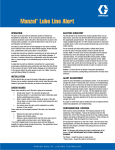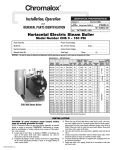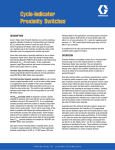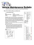
1
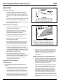
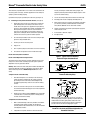
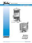
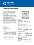
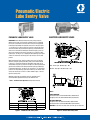
Pneumatic/Electric
Lube Sentry Valve
ELECTRIC LUBE SENTRY VALVE
PNEUMATIC LUBE SENTRY VALVE
OPERATION: Initiate lubricant flow from the lube pump serving the
divider valve or pump to point system (until flow has been established,
the electric or pneumatic circuit to the Lube Sentry must be bypassed).
Lubricant passing through the hydraulic section of the valve (See Figure
1 or 2) from port (1) to port (2) moves to piston (3) in the direction of the
arrow. The actuator rod (4) is attached to piston (3) and simultaneously
moves in the same direction allowing the directional spool (5) in the air
valve of the Pneumatic Lube Sentry (See Figure 1) to permit air to flow
between port “A” and port “C” or tripping the microswitch(es). (See Figure
2 Note 2 on the Electric Lube Sentry.) The Lube Sentry is now in a flow
position.
When lubricant flow stops, spring (6) returns piston (3) in the opposite
direction, closing the porting to the lube outlet (7). The lubricant ahead
of piston (3) is forced back through the adjustable needle valve (8) at a
controlled rate. As piston (3) returns to the right, the attached actuator rod
(4) moves the Pneumatic Lube Sentry directional spool (5) permitting air
to now flow between port “A” and port “B” (See Figure 1), or changing the
position of the microswitch(es) (See Figure 2 Note 2) on the Electric Lube
Sentry. The Lube Sentry is now in a no-flow condition. Figure 1 shows a
typical no-flow position.
Flow - Green Light - ON; Red Light - OFF
No-Flow - Red Light - ON; Green Light - OFF
Adjusting needle valve (8) clockwise increases shutdown time. A
counterclockwise adjustment decreases the shutdown time.
Note 1: Pneumatic Valve Operation (During Lubricant Flow)
Note 2:
FLOW CONDITION :
For Closed Contact: Use Red and Blue Wires (Red Common)
For Open Contact: Use Red and White Wires (Red Common)
Operation
Port “A”
Port “B”
Port “C”
Norm. Open
Air In
Plugged
Air Out
Norm. Closed
Air Out
Air In
Plugged
Figure 1. Pneumatic Lube Sentry Valve
NO-FLOW CONDITION:
For Open Contact: Use Red and Blue Wires (Red Common)
For Closed Contact: Use Red and White Wires (Red Common)
CAUTION: If only two of the three wires are used, tape un-used wire.
Figure 2. Electric Lube Sentry Valve
45425
Manzel® Pneumatic/Electric Lube Sentry Valve
INSTALLATION
General Lube Line Connection
1.
The Lube Sentry Valve should be located in the lube line
downstream of pump, filters, and controls, but ahead of the
master divider valve. (A high-pressure line filter placed after
the pump is insurance against system plugging due to oil-born
dirt.)
2.
A pressure rupture assembly (Disk Relief Type) must be located
in the main lube line between the pump and the line filter.
3.
NOTE: Do not use below minimum recommended
flow rates or inconsistent shutdown times occur.
Always install Lube Sentry with “LUBE OUT” port up, to permit
natural air purging of the device.
Graph 1. Minimum Flow Rate
General Shutdown Reaction Adjustment
1.
See graphs for minimum flow rates, with various viscosity oils,
and shutdown time recommendations.
2.
Start with the adjustment screw (Figures 1 & 2, Item 8)
flush with end of housing. Turn on lube system with pump
discharging oil at normal flow rate and pressure.
3.
Slowly rotate adjustment screw clockwise until the electric
switch/air valve changes mode (flow condition).
4.
Stop oil flow and note time for electric switch air valve to
change mode (no-flow condition).
5.
Start normal flow of oil and note that the electric switch/air
valve changes mode (flow condition) within two minutes and
remains in this mode as long as normal oil flow continues.
6.
For positive shutdown indication on the Electric Lube Sentry,
an ohmmeter or continuity meter should be connected to
wiring as follows: No flow condition – continuity between red
and white wires. Flow condition – continuity between red and
blue wires. Caution – In an explosive atmosphere, use only
approved device for checking continuity
7.
This is the minimum shutdown time attainable for the
application. The shutdown time can be increased by continuing
to turn the adjustment screw clockwise. Caution – Do not
adjust shutdown time greater than shown on graphs or
inconsistent shutdown time will result.
Pneumatic Lube Sentry Valve Installation
Pneumatic Connections
A. Series Type (in-line) Safety Control Pneumatic Circuits (See
Figure 3)
1.
Trace pneumatic safety circuits from the source of its take-off
air supply through the various safety devices used on the
engine and compressor to the entrance of the pilot air port
(bonnet port) on the safety control valve or gas shut-off valve.
2.
Select the most convenient location to break into the air circuit,
either between two other safety devices or between the last
safety device and the bonnet port of the safety control valve.
NOTE: At minimum flow rate, the shutdown time is not
adjustable. Times indicated are approximate results when
the attached procedure is followed. Attempting to increase
the shutdown time will result in inconsistent shutdown time.
Graph 2. Minimum Shutdown Time
3.
Break the air circuit at the selected point and tube the Lube
Sentry Valve into the circuit with air flow entering port “A” and
leaving port “C” (See Figure 1). If gas is used as the control
medium rather than air, tube the exhaust port “B” into a
suitable vent line.
CAUTION – Never plug port in series type shutdown circuits.
4.
To test device for operation, start engine to initiate flow in the
divider valve system. Operation of the air valve within the Lube
Sentry will be observed as the tripping out of the reset latch
(manual override) lever on the safety control valve (see Figure
3), and the continued operation of the engine.
After a short interval of running during which the engine and
compressor receive sufficient lubrication and all other safety
devices move to the RUN position, dump the output of the
pumps serving the divider valve systems by removing the
pump blowout disc or a pipe plug from the pump manifold
assembly. When the flow to the distribution system stops,
the Lube Sentry should operate to dump the pressure in the
pneumatic safety circuit, dropping out the safety control valve
to stop the engine. (If shutdown action is sluggish, reduce the
setting of the adjustable orifice through which air for the safety
circuit passes.
Page 2
45425
Manzel® Pneumatic/Electric Lube Sentry Valve
The Lube Sentry is provided with a 1/8” air valve. If the control orifice for
the safety system is too large, air will be supplied to the Lube Sentry too
quickly to permit it to dump properly.)
housing, consisting of conduit elbow and cap, nipple, and
adaptor by loosening and removing the adaptor, (Figure 7, Item
31) from the switch housing.
A pneumatic relay may be operated by the Lube Sentry (see Figure 4).
3.
Loosen setscrew (Item 26) located on bottom of switch body.
B. Parallel Type Safety Control Pneumatic Circuits (See Figure 5)
4.
Actuating piston must be completely extended (Item 15).
5.
Rotate switch enclosure screw (Item 23) clockwise until switch
just actuates. (Continuity is obtained between red and white
wires.) Rotate additonal 1/4 turn after switch actuates.
6.
Tighten setscrew (Item 26) to lock nylon ball (Item 25) against
switch enclosure screw.
7.
If microswitch is defective, replace.
8.
Re-adjust switch.
1.
Parallel type safety circuits rely on their devices to dump the
pilot control pressure on the safety control valve in case of
trouble. This control pressure is supplied to the pilot (bonnet)
port of the safety shutdown valve through an adjustable orifice
which permits enough air to enter the circuit to maintain
pressure on the port. When any safety device operates, the
pilot pressure is dumped, with the control orifice preventing
sufficient air to enter the system to maintain pressure.
2.
The Lube Sentry should be teed in to the line serving the pilot
port of the safety shutdown valve.
3.
Connect port “B” into the safety circuit.
4.
Plug port “C”.
5.
Port “A” (exhaust) may be connected to a vent line if necessary.
6.
To test device for operation see item 4 under Series Type.
Electric Lube Sentry Valve Installation
Electric Switch Adjustment and Replacement
Figure 3. Typical Series Installation of
Pneumatic Engine Shutdown Circuit
The electrical end of the Lube Sentry has been adjusted correctly at the
factory. If the electric switch assembly is replaced, repairs required or
adjustment necessary, proceed as follows:
Warning: Never remove the Lube Sentry Electric Switch Assembly from
the Actuator Assembly or make any adjustments to the Electric Switch
without first being sure there is NO Electricity Present at the Lube
Sentry.
To Replace Electric Switch Assembly
1.
After determining there is no electricity to the Lube Sentry,
remove the switch assembly from the actuator assembly
by removing the four-socket head screws holding the two
assemblies together, being careful not to scratch the mating
surfaces.
2.
Be sure no corrosion or dirt is present. In a no-flow condition,
the actuator rod should extend approx. 5/32 inches beyond the
actuator rod housing.
3.
Replace electric switch assembly. Caution: Do not reassemble
if scratches, dirt, or corrosion are present on mating surfaces
of switch and actuator assembly.
To Adjust Electric Switch Assembly
1.
2.
Page 3
With no lubricant flowing, Lube Sentry should be in shutdown
or warning position (switch actuated). You should show
continuity between red and white wires, if not, the microswitch
is misadjusted or broken.
If adjustment is required, remove the electrical connection
Figure 4. Typical Installation with
Pneumatic Indicating Relay
NOTE: Installation of the Pneumatic Lube Sentry as shown on
the drawing provides automatic signalling of cylinder lubrication
trouble. No flow caused by pump failure, broken line or low
oil supply will cause the Lube Sentry to operate, removing air
pressure from the fuel valve and stopping the engine.
Figure 5. Typical Parallel Gas Engine Installation of Lubriquip
Pneumatic Lube Sentry with Fulton-Sylphon No. 530
Pneumatic Pilot Valve
Ordering Information
Figure 7. Switch Assembly for Electric Lube Sentry
Description
Part No.
Old Part No.
Item
Pneumatic Lube Sentry, Complete
563506
527-100-190
22
Description
Part No.
Old Part No.
Qty.
Switch Assembly - Electric Lube Sentry
563504
527-100-170
Pneumatic Valve
563503
527-100-150
23*
1
• Switch Enclosure Screw
557355
503-680-000
Actuator
563502
527-100-130
1
24*
• Microswitch Assembly
557757
527-100-210
Electric Lube Sentry, Complete
563505
1
527-100-180
25*
• Nylon Ball, 5/32 in.
555781
504-706-000
Switch Assembly
563504
1
527-100-170
26*
• Setscrew, 10-32 x 3/8 in.
556476
417-450-040
1
27*
• Round Head Screw
555496
416-010-070
2
28*
• Int. Lockwasher
555631
421-070-010
2
29*
• Socket Head Srew, 1/4-20 x 1-3/4
556510
419-130-090
4
30
• Switch Housing
561008
527-100-090
1
31
• Adapter
557356
503-681-000
1
32
• Conduit Elbow w/Nipple
557384
507-912-000
1
563908
560-001-120
1
For more information on the Pneumatic or Electric Lube Sentry Valve consult Literature L15831
Figure 6. Actuator Assembly
Item
Description
1
Part No.
Lube Sentry Actuator Assembly
563502
Old Part No.
527-100-130
Qty.
1
2
• Body (Matched Fit)
560999
527-100-000
1
3
• Piston (Matiched Fit)
561000
527-100-010
1
4*
• Valve - Adjustment
561005
527-100-062
1
5*
• Housing Adjustment Screw
561004
527-100-052
1
6*
• O-Ring, Viton, 70 Duro
556560
422-041-140
2
7*
• O-Ring, Viton, 70 Duro
556551
422-040-060
1
8*
• Back-Up Ring
557719
527-000-760
2
9*
• O-Ring
556554
422-040-110
1
10*
• Setscrew, 1/4-20 x 1/4 Hex
555531
417-060-020
1
11*
• Ball, 3/16, Steel
556328
401-030-030
1
Figure 8. Valve Assembly for Pneumatic Lube Sentry
12*
• Spring-Piston Return
557753
527-100-110
1
Item
13*
• O-Ring
556557
422-040-140
1
22
14*
• Spacer, O-Ring Retaining
561009
527-100-100
1
23*
15*
• Piston-Switch Actuating
561002
527-100-030
1
16*
• Locking Screw, 3/8-24 x 3/16
556470
416-700-780
17*
• Back-Up Ring
556584
18*
• O-Ring
556553
19
• Screw - Piston Enclosure
20
*
Electric Switch Assembly Repair Kit
Description
Part No.
Old Part No.
Qty.
Valve Assembly - Pneumatic Lube Senry
563503
527-100-150
1
• O-Ring, 70 Duro
555690
422-041-200
1
24*
• O-Ring, 70 Duro
555685
422-040-220
1
1
25*
• Air Valve Spring
557353
503-658-000
1
423-700-038
1
26*
• Valve Cartridge
557354
503-659-000
1
422-040-080
1
27*
• Spring Guide
561011
527-100-320
1
561003
527-100-040
1
28*
• Socket Head Screw, 1/4-20 x 1-3/4
556510
419-130-090
4
• Houseing - 5 W. Act. Piston
561001
527-100-020
1
29
• Air Valve Housing
561006
527-100-070
1
–
Adjustment Screw & Housing Only
564405
527-100-370
1
30
• Air Valve Enclosure Screw
561007
527-100-080
1
*
Actuator Assembly Repair Kit
564436
560-001-130
1
*
Pneumatic Lube Sentry Repair Kit
563907
560-001-110
1
Specifications
Material
Steel
Operating Temperature
-20ºF to 180ºF (-29ºC to 82ºC)
Max Pressure
6,000 psi (414 bar)
Max Air Pressure (Pneu.)
125 psi (8 bar)
(1) Flow Rate (per day)
4 - 400 pints (1.89 - 189.2 liters)
Elecrical Rating
Pressure Drop
250 psi (17 bar)
Seals
Viton
1) 5 amps @ 125/250 VAC
2) A, B or C @ 28 VDC
(A) Inductive - 3 amp
(B) Resistive - 5 amp
(C) Max Inrush - 15 amp
(1) Lubricant
Oil (450 - 2,000 SUS)
Net Weight
5 lb (2.265 kg)
(1) Ref to Graph 1
All written and visual data contained in this document are based on the latest product information available at the time of publication. Graco reserves the right to make changes at any time without notice.
Contact us today!
To receive product information or talk with a Graco representative,
call 800-533-9655 or visit us online at www.graco.com.
©2006-2009 Graco Inc. Form No. L45425 Rev. B 7/09 Printed in U.S.A. All other brand names or marks are used for identification purposes and are trademarks of their respective owners. All written and
visual data contained in this document are based on the latest product information available at the time of publication. Graco reserves the right to make changes at any time without notice.