1
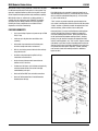
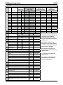
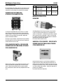
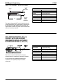
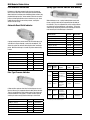
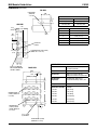
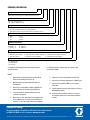
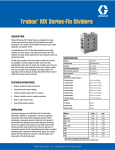
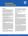
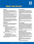
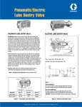
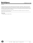
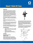
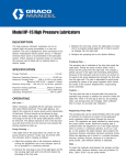
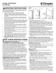
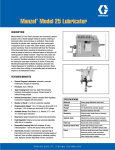
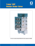
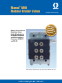
Manzel MHH
Modular Divider Valves
®
Modular, Series-Progressive,
Divider Valve Delivers
Positive Oil Lubrication for
Gas Engines, Compressors
and Similar Equipment at
Pressures up to 6000 PSI
and 7500 PSI
Available Electronic Only
MHH valve
s
are a dire
ct
replaceme
nt fo
MHP valve r
s. *
*MHP part numbers will automatically be superseded by the Graco GEDI order entry system.
MHH Modular Divider Valves
MHH divider valves precisely proportion a volume of oil to satisfy
the different requirements of every point in a lube system. They
operate in sequential fashion to ensure that no point is missed.
Series-Progressive design provides ready monitoring capability.
MHH divider valves are available for use with petroleum or
synthetic oils and at pressures up to 7500 PSI. The modular,
stackable sub-plate design provides maximum application
flexibility. Accessory components are available for visual
diagnostics and electrical monitoring.
FEATURES/BENEFITS
•
Use in terminating oil systems at pressures up to 7500
PSI (517 bar)
•
Lubricate up to 16 points from one divider valve
assembly.
•
Soft-seal O-ring construction and indicator ports
minimize leakage and reduce maintenance.
•
Built-in check valves prevent lube back flow and help
keep lube lines full.
•
Stackable sub-plate design simplifies build-up,
installation and maintenance.
•
Ample clearance between outlet connections for
elbows and 3/8" lube lines.
•
Performance indicators, cycle indicators and proximity
switches monitor divider valve action to simplify
troubleshooting and repair.
•
Choice of SAE or NPSF inlet and outlet connections
•
Choice of 70 Durometer Buna-N or 90 Durometer
fluoroelastomer O-rings.
L10103
DESCRIPTION
Each MHH divider valve assembly incorporates from three to
eight working piston sections (1), associated sub-plate sections
which include the outlet distribution ports (2), an inlet section
(3), and an end section (4).
“Twin” sections are ported to provide separate outputs from
each end of a working piston and direct them to two lube points.
“Single” sections are ported to combine the outputs from each
end of a working piston and direct it to one lube point.
Cross port plates (5) may be installed between working piston
sections and sub-plate sections to combine the outputs of
successive working piston sections. (Cross port plates must
not be installed beneath bottom working sections.) Singling
plates (6) may be installed to combine the outputs from both
ends of a working piston in any "Twin" section. Bypass sections
(not shown) may be used in place of working piston sections to
eliminate inactive lube lines without disturbing active lube lines,
or to provide for future system expansion. (Divider assembly
must contain at least three working sections in addition to
bypass section.)
Page 2
MHH Modular Divider Valves
L10103
COMPONENTS
Output Volume
Key
Size
1
6T
–
Description
MHH (High Pressure
fluoroelastomer
90 Durometer O-Rings)
in3
cm3
Part No.
Old Part No.
Part No.
Old Part No.
.006 Twin
0.006
0.098
562667
106-000-085
562685
106-000-595
6S
.006 Single
0.012
0.197
562661
106-000-025
562679
106-000-465
9T
.009 Twin
0.009
0.149
562668
106-000-095
562686
106-000-605
9S
.009 Single
0.018
0.295
562662
106-000-035
562680
106-000-475
12T
.012 Twin
0.012
0.197
562669
106-000-105
562687
106-000-615
12S
.012 Single
0.024
0.393
562663
106-000-045
562681
106-000-485
0.018
0.295
562670
106-000-115
562688
106-000-625
562676
106-000-235
.018 Single
0.036
0.590
562664
106-000-055
562682
106-000-495
562674
106-000-205
24T
.024 Twin
0.024
0.393
562671
106-000-125
562689
106-000-635
562677
106-000-245
24S
.024 Single
0.048
0.787
562665
106-000-065
562683
106-000-505
564252
106-000-215
30T
.030 Twin
0.030
0.492
562672
106-000-135
562690
106-000-645
562678
106-000-255
30S
.030 Single
0.060
0.983
562666
106-000-075
562684
106-000-515
562675
106-000-225
562660
106-000-010
Bypass
Intermediate Sub-plate*
Old Part No.
1/8-27 NPSF
563425
–
3
Inlet w/Bleed
563421
–
4
End Section*
563424
–
5
Cross port plate - Right+#
563469
527-005-320
Cross port plate - Left+#
563470
527-005-330
Cross port plate - Both+#
563471
527-005-340
Singling Plate+#
563472
527-005-350
Key Description
Part No.
Old Part No.
7/16-20 SAE
563451
527-003-550
563422
527-000-325
Old Part No.
3 Section
557731
527-001-930
4 Section
557732
527-001-940
5 Section
557733
527-001-950
6 Section
557734
527-001-960
7 Section
557735
527-001-970
8 Section
557736
527-001-980
8
Tie Rod Nut Only
556371
410-440-010
9
Valve Block Mounting Screw
556513
419-140-070
10
Piston Enclosure Plug
557716
527-000-232
11
Piston Enclosure O-Ring, 70 Buna-N
556568
422-210-040
Piston Enclosure O-Ring, 90 fluoroelastomer
556570
422-240-040
12
Indicator Port Plug
557776
527-300-840
13
Indicator Port O-Ring, 70 Buna-N
556567
422-210-030
Indicator Port O-Ring, 90 fluoroelastomer
556569
422-240-030
70 Duro, Buna-N O-Ring
556540
422-010-060
90 Duro, fluoroelastomer O-Ring
122276
–
Valve Block Mounting Screw for use w/cross port and
Singling Plates
556514
419-140-080
15
Page 3
NOTE:
* Part numbers include standard Buna-N
70 Durometer seals for 6000 PSI
maximum system pressure. Consult
Graco for fluoroelastomer 90 Durometer
(7500 PSI) seals.
Working piston sections are also
available with cycle indicators mounted
on the left-hand side, but limit maximum
operating pressure to 3500 psi.
Part No.
14
Old Part No.
.018 Twin
1/4-18 NPSF
7
Part No.
18T
Key Description
6
w/Cycle Pin *+
Right Hand Side
18S
Part No.
2
MHP valves have been
superseded by MHH valves
shown at right
Tie Rod (3 req'd)
When requested, cross porting and
singling can be accomplished by using
appropriate plates.
+ Part numbers include appropriate
mounting screws.
# Part numbers include 90 Durometer
fluoroelastomer seals for 7500 PSI
maximum system pressure.
MHH Modular Divider Valves
CYCLE INDICATORS
By sensing divider valve piston movement, lube volume can be
accurately monitored and controlled. A variety of mechanical
and electrical cycle indicators are available for this purpose.
DIVIDER VALVE SECTIONS WITH
ATTACHED CYCLE INDICATOR PIN
L10103
Type
Rating
Part No.
Old Part No.
SPDT
20.0A @ 125, 250 VAC
0.50A @ 125 VDC
0.25A @ 250 VDC
563272
510-599-000
10.0A @ 125, 250 VAC
0.30A @ 125 VDC
0.15A @ 250 VDC
564357
510-577-000
DPDT
MAGNETIC VISUAL CYCLE
INDICATOR
18 through 30 size MHH divider valve sections are available
with a factory-installed cycle indicator pin attached to either
end of the piston. The pin moves in and out one time for each
complete cycle of the divider valve assembly. Application
pressure is limited to 3500 PSI.
See Page 3 for part numbers. Consult Graco for part numbers
of sections with pin on left-hand side and for part numbers of
sections with fluoroelastomer seals.
CYCLE INDICATOR SWITCH - FOR USE WITH
DIVIDER VALVE SECTION HAVING ATTACHED
CYCLE INDICATOR PIN
Switch bracket clamps to a cycle indicator pin housing. Cycle
indicator pin movement repeatedly trips an electrical (limit)
switch. Switch pulses provide input to a system controller
which counts them to control and verify completion of the lube
cycle.
A No-Weep Magnetic Visual Cycle Indicator can be installed
in place of a piston enclosure plug on any size divider valve
section. Six steel balls in a transparent sleeve follow a magnet
which moves with the cycling piston. Unlike a cycle indicator
pin, working section displacement is not reduced. Suitable for
application at pressures up to 7500 PSI. Part number 563251 (509-932-522)
UNIVERSAL CYCLE COUNTER - FOR USE WITH
DIVIDER VALVE SECTION HAVING ATTACHED
CYCLE INDICATOR PIN
Counter housing clamps to a cycle indicator pin housing. A
6-digit mechanical counter, advanced by the movement of a
divider valve cycle indicator pin, provides visual assurance that
the system is functioning. Every “count” indicates one complete
cycle of the divider valve assembly. Suitable for application at
pressures up to 3500 PSI.
Part number 563444 (527-002-410)
Page 4
MHH Modular Divider Valves
L10103
REED-TYPE PROXIMITY SWITCH (OPTIONAL)
(2) 22 GA
WIRES
48 IN. LONG
7/16-20
THRD.
1.125 DIA.
SPECIFICATIONS
Material
Stainless Steel, Aluminum
Switch Rating
1.2 Volt-Amperes; up to 115 VAC, 50 VDC
Contacts
Single Pole, Single Throw
Ambient Temperature 0º F to 130º F (-18º C to 55º C)
3.687
1/2 IN. NPT
FEMALE
CONDUIT
CONNECTION
Operating Pressure
7,500 psi (max)
Cycle Rate
60 cpm (max)
Cycle Life Expectancy 10,000,000+ Cycles
Part No.
563427 (527-001-231)
This magnetically operated SPST switch is installed in place of
a piston enclosure plug. This "unattached pin" type switch can
be used with any size MHH working section An indicator type
magnet follows the divider valve piston, opening and closing the
switch as it moves back and forth.
FIELD-SENSITIVE-MECHANICAL (FSmech)
PROXIMITY SWITCH FOR HAZARDOUS
ENVIRONMENTS (SUPPLIED AS STANDARD
WITH MENU CODE OPTIONS E, F, G, M, N, P)
SPECIFICATIONS
Current Rating
1.2 Volt-amps @ 28 VDC; 5A Resistive @ 115, 230 VAC
Temperature Range
-58º F to 167º F (-50º C to 75º C)
Normally Open Contacts
Cycle Rate
This mechanical switch is installed in place of a piston
enclosure plug and is actuated by the movement of the piston.
It can be used with any size MHH working section and
is suitable for use in systems operating in hazardous
environments.
Page 5
150 cpm (max)
Cycle Life Expectancy 10,000,000+ Cycles
Operating Pressure
7,500 psi (max)
CSA Certified
For CL1: Groups A, B, C and D; Div. 1
Part No.
563485 (527-006-060)
MHH Modular Divider Valves
L10103
Spring-Type Pressure Indicator with Memory
PERFORMANCE INDICATORS
Performance indicators respond to the increase in pressure
which occurs when lube lines or lube points become blocked.
When installed in indicator ports of working piston sections, they
pinpoint blockage location. Some models relieve the excessive
pressure, allowing the divider valve to continue to cycle. Some
models do not relieve the excessive pressure, causing the
divider valve to lock up.
Automatic Reset Relief Indicator
A spring-loaded piston unseats when lube line blockage occurs
and lubricant escapes through a vent to the atmosphere. This
allows the system to continue lubricating the other unaffected
points. When the blockage is cleared, the piston automatically
reseats.
Relief Pressure
Part No.
Old Part No.
750 psi (52 bar)
563170
508-310-415
1,000 psi (69 bar)
563171
508-310-425
1,250 psi (86 bar)
563172
508-310-435
1,500 psi (104 bar)
563173
508-310-445
2,000 psi (138 bar)
563174
508-310-455
2,500 psi (173 bar)
563175
508-310-465
3,000 psi (207 bar)
563176
508-310-475
When blockage occurs, a spring-loaded piston unseats and
forces a separate indicator pin to protrude from the body of
the indicator. There is no provision for relief, and the pressure
escalates until relieved elsewhere in the system. The spring
automatically reseats the piston but the indicator pin must be
reset manually after the blockage is eliminated.
Relief Pressure
Part No.
Old Part No.
250 psi (17 bar)
563252
509-932-590
500 psi (35 bar)
563253
509-932-600
750 psi (52 bar)
563254
509-932-610
1,000 psi (69 bar)
563255
509-932-620
1,500 psi (103 bar)
563256
509-932-630
2,000 psi (138 bar)
563257
509-932-640
2,500 psi (173 bar)
563258
509-932-650
3,000 psi (207 bar)
563261
509-932-831
5,000 psi (345 bar)
563262
509-932-832
Part No.
Old Part No.
OUTLET CHECK VALVES
Max
Operating
Pressure
Cracking
Pressure
Description
NPT Divider Valve Outlet Check Valves
Disc-Type Pressure Indicator
10 psi
35 psi
5,000 psi
120 psi
250 psi
1/8-27 M x 1/8-27
F NPFT; NPSF;
Carbon Steel; Hard
Seat
360 psi
7,500 psi
A blow-out disc ruptures when lube line blockage occurs and
lubricant forces a pin to protrude from the body of the indicator.
There is no provision for relief and the pressure escalates until
relieved elsewhere in the system. The disc must be replaced
and the pin reset manually after the blockage is eliminated.
Relief Pressure
Part No.
Old Part No.
2,800 psi (193 bar)
563229
509-499-625
3,700 psi (255 bar)
563221
509-499-105
4,600 psi (317 bar)
563222
509-499-125
5,500 psi (380 bar)
563224
509-499-145
6,400 psi (441 bar)
563226
509-499-165
35-60 psi
1/8-27 M x 1/4-18
F NPFT; NPSF;
Stainless Steel;
Soft Seat
563195
509-350-010
563196
509-350-030
563197
509-350-120
563198
509-350-250
563051
463-001-582
564325
463-001-580
SAE Divider Valve Outlet Check Valves
3,500 psi
20-50 psi
7/16-20 M X 7/1620 F; Stainless
Steel; Hard Seat
–
–
7,500 psi
20-50 psi
7/16-20 M x 7/1620 F; Stainless
Steel; Soft Seat
–
463-001-585
Outlet check valves enhance system integrity by ensuring that contaminants, air or gases
do not back up into the lubrication system.
Page 6
MHH Modular Divider Valves
L10103
DIMENSIONS Inches/(mm)
TOP VIEW
BLEED SCREWS
(TORQUE TO
1-2 FT-LBS)
1.500
(38.1)
Port Sizes
.781
(19.9)
SIDE VIEW
1.656
(42.06)
2.188
(55.56)
Inlet
Outlet
1/4-18 (F) NPSF
1/8-27 (F) NPSF
7/16-20 (F) SAE
7/16-20 (F) SAE
Qty of Section
1.125
(28.58)
LUBE
INLET
.406
(10.31)
.734
(18.85)
LUBE OUTLET
(TYPICAL)
"A"
3
3.578 (90.88)
4
4.500 (114.30)
5
5.422 (137.71)
6
6.344 (161.13)
7
7.266 (184.55)
8
8.188 (207.97)
PISTON ENCLOSURE PLUG (TYPICAL)
(TORQUE TO 12-15 FT-LBS)
.922 (TYP)
(23.41)
SPECIFICATIONS
OUTLET IS PLUGGED ON
ONE SIDE WHEN WORKING
SECTION IS SINGLED
FRONT VIEW
3.000
(76.2)
1.750
(44.4)
.625
(15.9)
.484
(12.3)
"A"
MOUNTING SCREW
(TYPICAL) (TORQUE TO
8-9 FT-LBS)
.484
(12.3)
.28
(7.1)
INDICATOR PORT
(TYPICAL) (SPECIAL
THREAD, TORQUE TO
8-9 FT-LBS)
.281 (7.137) DIA
(4) MTG HOLES
TIE ROD AND NUT (TYPICAL)
(TORQUE TO 5-8 FT-LBS)
Page 7
Material
Steel Body (Corrosion Protected)
Steel Piston (Honed Fit)
Lubricant
Petroleum or Synthetic Oil only
Max Pressure
6,000 psi for Petroleum Oil only
7,500 psi for Petroleum or Synthetic Oil
Max Operating
Temperature
Buna-N O-Rings: 200º F (93º C)
Fluoroelastomer O-Rings: 350º F (163º
C)
Max Cycle Rate
200 cpm
Divider Valve Assembly
Net Weight
3 Section
5.9 lb (2.7 kg)
4 Section
7.3 lb (3.3 kg)
5 Section
8.7 lb (4.0 kg)
6 Section
10.2 lb (4.6 kg)
7 Section
11.6 lb (5.6 kg)
8 Section
13.0 lb (5.9 kg)
ORDERING INFORMATION
XXX
–
XXX
–
X
–
X
–
XX
–
X
–
XX
SERIES OF DIVIDERS
MHH - High Pressure Compressor to 7,500 psi (fluoroelastomer seals)
INLET - OUTLET THREADS
NPT - Inlet 1/4-18, Outlet 1/8-27
SAE - Inlet 7/16-20, Outlet 7/16-20
DIVIDER VALVE ACCESSORY OPTIONS (OMIT WHEN NOT REQUIRED)
P - Assembly of Performance Indicators (in all working outlets **)
C - Assembly of External Check Valves (in all working outlets **)
B - Assembly of Performance Indicators & Check Valves (in all working outlets **)
NUMBER OF SECTIONS
3 - Three
4 - Four
5 - Five
6 - Six
7 - Seven
8 - Eight
WORKING SECTION CAPACITY
06 - 0.006 cu. in.
09 - 0.009 cu. in.
12 - 0.012 cu. in.
18 - 0.018 cu. in.
24 - 0.024 cu. in.
30 - 0.030 cu. in.
BP - Bypass
TYPE OF VALVE SECTION
T - Twin Valve
B - Twin Valve w/Cycle Pin Right
H - Twin w/Cycle Pin Left
S - Single Valve - RH Outlet
C - Single Valve w/Cycle Pin Right - LH Outlet
J - Single w/Cycle Pin Left - RH Outlet
L - Single Valve - LH Outlet
D - Single Valve w/Cycle Pin Right - RH Outlet
K - Single w/Cycle Pin Left- LH Outlet
CROSS PORTING OPTION (OMIT WHEN NOT REQUIRED)
CR - Right Hand Side
CL - Left Hand Side
CB - Both Sides
**Performance Indicator/Check Valve part number must be
specified on order.
If a Proximity Switch is required, order as a separate item
(see bulletin L15600).
NOTES:
1. Right/left hand is determined when viewing front of
divider valve assembly with inlet at top.
2. Working sections are specified starting from inlet
section down.
3. When valve is cross ported, its outlet is plugged and
output is diverted to next valve farthest from inlet.
4. Last valve in divider assembly, farthest from inlet,
cannot be cross ported.
5. When valve is a twin, both outlets in its sub-plate must
be used. When valve is a single, only one outlet in its
sub-plate can be used and the other must be plugged.
6. Single valve can be cross ported on one side only.
7. Cycle pins are limited to applications of 3,500 psi max.
8. Cycle pins are available on MHH 18, 24 & 30 size
valves only.
9. Fsmech proximity switches can be used on all sizes of
MHH working sections.
10. All divider valve assemblies must have a minimum
of 3 working sections and a maximum of 8 working
sections.
All written and visual data contained in this document are based on the latest product information available at the time of publication. Graco reserves the right to make changes at any time without notice.
Contact us today!
To receive product information or talk with a Graco representative,
call 800-533-9655 or visit us online at www.graco.com.
©2006-20011 Graco Inc. Form No. L10103 Rev. D 01/12 Available online only All other brand names or marks are used for identification purposes and are trademarks of their respective owners. All written
and visual data contained in this document are based on the latest product information available at the time of publication. Graco reserves the right to make changes at any time without notice.