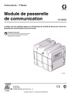
1
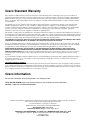
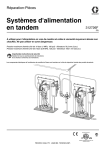
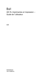
Instructions - Parts Communications Gateway Module Installation Kit 3A1704G EN For use with HFR™, VRM™, and VPM™ systems to provide fieldbus communications abilities. For professional use only. Kit 24J415 Important Safety Instructions Read all warnings and instructions in your system manual. Save all instructions. ti11985a CGM with DeviceNet connector shown Kits Contents Related Manuals Kits . . . . . . . . . . . . . . . . . . . . . . . . . . . . . . . . . . . . . . 2 Related Manuals . . . . . . . . . . . . . . . . . . . . . . . . . . . 2 Overview . . . . . . . . . . . . . . . . . . . . . . . . . . . . . . . . . . 2 Installation . . . . . . . . . . . . . . . . . . . . . . . . . . . . . . . . 3 Setup . . . . . . . . . . . . . . . . . . . . . . . . . . . . . . . . . . . . . 5 Maintenance . . . . . . . . . . . . . . . . . . . . . . . . . . . . . . . 8 Available Internal Data . . . . . . . . . . . . . . . . . . . . . . 9 Parts . . . . . . . . . . . . . . . . . . . . . . . . . . . . . . . . . . . . 24 Graco Standard Warranty . . . . . . . . . . . . . . . . . . . 26 Graco Information . . . . . . . . . . . . . . . . . . . . . . . . 26 Manual Kits The following kit is the Communications Gateway Module (CGM) hardware/software and is required for all installations. The kit is used in conjunction with the correct fieldbus device. CGM Part No. 24J415 Description CGM Installation Kit (Required) The following kits work with kit 24J415 and includes all remaining parts necessary to install a CGM. See manual 312864 for repair parts for each assembly. CGM Part No. Fieldbus CGMDN0 DeviceNet CGMEP0 EtherNet/IP CGMPB0 PROFIBUS CGMPN0 PROFINET 3A1974 CAN Adapter Kit, Instructions 312864 Communications Gateway Module, Instructions - Parts 313997 HFR Operation 313998 HFR Repair - Parts 313873 VRM Operation 313874 VRM Repair - Parts 313875 VPM Operation 312764 VPM Repair - Parts 406987 GCA CAN Cables, Reference Overview The Communications Gateway Module (CGM) provides a control link between the HFR, VRM, or VPM system and a selected fieldbus. This provides the means for remote monitoring and control by external automation systems. The data available by the CGM to the fieldbus depends on which GCA based system is connected. Unique data maps are defined for each GCA system and are available on the token provided in the kit. See Available Internal Data on page 9 for a list of internal data from the HFR, VRM, or VPM system that can be viewed or modified by your fieldbus master. NOTE: The following system network configuration files are available at www.graco.com • • • 2 Description EDS file: DeviceNet or Ethernet/IP fieldbus networks GSD file: PROFIBUS fieldbus networks GSDML: PROFINET fieldbus networks 3A1704G Installation Installation 2. Install access cover (D). 3. Connect CAN cable from either CAN connection on the CGM to any CAN connection found on any other GCA device located on the machine. Attach the ferrite suppressor to CGM end of the CAN cable. For additional extension cables, see GCA CAN Cables Reference manual. 1. Install the CGM in the desired location. a. Remove access cover (D). Loosen two screws (C) and remove CGM (A) from base (B). C NOTICE To avoid severe damage to GCA modules, ensure the CAN cable is connected to the appropriate CAN connection. A NOTICE To avoid severe machine damage, do not connect any CAN device to connectors 2A, 2B, or 2C on the Motor Control Module. Connectors 2A, 2B, and 2C are not CAN connectors. D NOTE: If there are no free CAN ports, plug splitter (121807) into the CAN distribution block located in the Power Distribution Box (PDB). Connect the CAN cable into the splitter. For more detail, refer to the CAN Adapter Kit manual. B FIG. 1 b. NOTE: CAN ports are located on the base of cube shaped GCA modules or port 6 on the High Power Temperature Control Module. Mount base (B) in desired location with four screws supplied in this kit. See the following mounting dimensions. #10-32 UNF (M5 x 0.8) 2.75 in. (69.9 mm) CAN Connector 2 CAN Connector 1 ti11972a FIG. 2: Cable Connections 3.25 in. (82.6 mm) c. Mount CGM (A) on base (B) with two screws (C). 3A1704G 3 Installation 4. If used, connect the ethernet, DeviceNet, or PROFIBUS cable to the CGM as applicable. Connect the other end of the cable to the FieldBus device. ti11985a FIG. 3: Cable Connections 5. Connect cable (LC0032) to the MCM, port 2B, and a customer provided signal device. The signal device must have isolated, dry contacts. 6. Perform the Install or Update Data Map procedure in CGM manual 312864. 7. See Available Internal Data on page 9 for details on FieldBus pinout setup. 8. Perform Setup on page 5 to configure the fieldbus. 4 3A1704G Setup Setup Gateway Screens Fieldbus Screens Page PROFIBUS 5 PROFINET 6 DeviceNet 7 EtherNet/IP 7 PROFIBUS Fieldbus Screens These screens are shown only if you have a PROFIBUS Fieldbus CGM installed. See Kits on page 2. Screen 1 This screen enables the user to set the device address, install date, location tag, function tag, and description. The Gateway screens are used to configure the fieldbus. These screens are shown only if a CGM is correctly installed in your system. See Installation on page 3. 1. With the system on and enabled, press to access the Setup screens. 2. Press the left arrow key once to navigate to the main Gateway screen. See FIG. 4. FIG. 5: PROFIBUS Fieldbus Screen 1 Screen 2 This screen displays the hardware revision, system serial number, and data map identification information. FIG. 4: Example Fieldbus Screen FIG. 6: PROFIBUS Fieldbus Screen 2 3A1704G 5 Setup PROFINET Fieldbus Screens These screens are shown only if you have a PROFINET Fieldbus CGM installed. See Kits on page 2. Screen 1 Screen 3 This screen displays the hardware revision, system serial number, and data map identification information. This screen enables the user to set the IP address, DHCP settings, subnet mask, gateway, and DNS information. FIG. 9: PROFINET Fieldbus Screen 3 FIG. 7: PROFINET Fieldbus Screen 1 Screen 2 This screen enables the user to set the station name, install date, location tag, function tag, and description. FIG. 8: PROFINET Fieldbus Screen 2 6 3A1704G Setup EtherNet/IP Fieldbus Screens DeviceNet Fieldbus Screen These screens are shown only if you have a EtherNet/IP Fieldbus CGM installed. See Kits on page 2. This screen is shown only if you have a DeviceNet Fieldbus CGM installed. See Kits on page 2. Screen 1 This screen enables the user to set the device address and baud rate, and to view the hardware revision, system serial number, data map identification information. This screen enables the user to set the IP address, DHCP settings, subnet mask, gateway, and DNS information. FIG. 12: DeviceNet Fieldbus Screen FIG. 10: EtherNet/IP Fieldbus Screen 1 Screen 2 This screen displays the hardware revision, system serial number, and data map identification information. FIG. 11: EtherNet/IP Fieldbus Screen 2 3A1704G 7 Maintenance Maintenance Install Upgrade Tokens NOTE: The Motor Control Module, Fluid Control Module, and Temperature Control Module connection to the system is temporarily disabled during the installation of upgrade tokens. To install software upgrades: 1. Use correct software token stated in the table. See Graco Control Architecture™ Module Programming manual for instructions. r_257396_3b9905_04b ti12334a1 NOTE: Upgrade all modules in the system to the software version on the token, even if you are replacing only one or two modules. Different software versions may not be compatible. All data in the module (System Settings, USB Logs, Recipes, Maintenance Counters) may be reset to factory default settings. Download all settings and user preferences to a USB before the upgrade, for ease of restoring them following the upgrade. ti12358a1 ti12354a1 FIG. 13: Remove Access Cover See manuals for locations of specific GCA components. The software version history for each system can be viewed in the technical support section at www.graco.com. Token Application 16H821 HFR: - Communication Gateway Module 16G365 VPM: - Communication Gateway Module VRM: - Communication Gateway Module 8 3A1704G Available Internal Data Available Internal Data The following internal data with this system can be viewed and modified by your fieldbus master. NOTE: Refer to appropriate system manual for machine operation instructions. Units System Status In Byte CGM Input from PLC Output CGM Output to PLC Input Descriptions (Bit Number | Name) 0 | Heartbeat 1-2 Needs to follow the CGM Output. 1 | Status of Dispense 2 | Dispense Valve (1 = Open) 0 = Close Dispense Valve 3 | Ratio Check Valve (1 = Enabled) 1 = Open Dispense Valve 0 = Enable Dispense Valve 1 = Enable Ratio Check Valve 4 | Pump Parked (1 = Parked) 3A1704G Out Byte 1= Begin Park 1-2 Square wave CGM initiates a square wave that toggles every toggles every 3 sec. The PLC must 3 sec. follow the heartbeat. If the heart beat is lost from the PLC or CGM then the system will shutdown. If the PLC does not detect the heartbeat then the PLC should cycle the PLC output bit HI/LO in attempt to establish the heartbeat from the CGM. If no heartbeat is detected then a disconnected cable or major error may exist in the CGM. 1= Dispense Monitor Only: On Circulation sysActive, tems, this indicates that a dispense is pending or in progress (or when pre dispense timer is active and dur0 = Dispense ing a dispense).On an L-head sysnot active tem Dispense Valve is considered open until the end of the clean out cycle. On other types of systems the bit will indicate a dispense is active. 0 = Dispense Used in diagnostics only. Not to be Valve Closed, used to control a dispensed shot. 1 = Dispense Valve Open 0 = Dispense Valid for VRM/VPM, Infusion/Paste systems only. Initiating a Dispense Valve is cycle will dispense material out of enabled the Ratio Check valves when in 1 = Ratio Ratio Check mode. When bit is OFF Check Valve the material will dispense normally is enabled thru the Dispense valve. 0 = Pump is Parking the pump involves moving not Parked, 1 the Red pump to the position which the pump shaft is least exposed to = Pump is the atmosphere. System must be in Parked Standby mode. Chemical will dispense out of the dispense valve. 9 Available Internal Data Units System Status In Byte CGM Input from PLC Output 5 | DV Lockout / Circu- 1-2 0 = Unlock Dislation Control pense Valve, (1 = Locked out) Non-Circulation State 1 = Lockout Dispense Valve , Circulation State 6 | Mix head Cleanout (1 = Closed) 7 | SYSTEM STARTUP BIT (1 = On) Valid for Circulation systems ONLY 8 | Not Used 9 | Prime Side (1 = Blue) 0 = Open Clean Out 1 = Close Clean Out 0 = Stop System Startup 1 = Start System Startup Not Used 0 = RED 1 = BLUE 10 Out Byte CGM Output to PLC Input 1-2 0 = Dispense Valve is unlocked or in Non-Circulation State Descriptions Used to lock out the dispense valve or configure to circulation mode (circulation type system) when in standby/operator or operator/night modes only. Only for stall to pressure systems with an electric dis1 = Dispense pense valve or any stall to pressure Valve is dispense valve configuration (circulocked out or lation type system). in Circulation State 0 = Clean Out Used for L-Head systems cleanout / diagnostics only. is open 1 = Clean Out is closed System Startup bit will initiate a con0 = System Startup OFF trolled startup of the system. The temperature conditioning zones will 1 = System be initiated when the bit is high. Low Startup ON pressure recirculation is also enabled when the bit is set (Standby and night modes). Turning off this bit will turn OFF the temperature conditioning zones and circulation. For stall to pressure systems with a manual dispense valve, setting this bit will configure the pumps to stall to the pressure set point. For stall to pressure systems, set to operator mode and set the DV Lockout / Circulation Control bit to high. Setting this bit will start a recirculation dispense for recirculation type systems. Not Used Not Used 0 = RED Selects which pump- Red or Blueto dispense from in prime mode. 1 = BLUE Used for priming the chemical thru the pumps and hoses. Valid for VRM/VPM, Infusion/Paste systems only. Initiating a Prime shot is via the ADM or the Footswitch. Chemical will dispense out of the Ratio check valves if the system is not setup for circulation. 3A1704G Available Internal Data Units 10 | Base Purge (1 = On) System Status 11 | Recirc Status (1 = High Pressure Recirc) CGM Input from PLC Output In Byte 13 | PLC Disables dispensing 14 | CGM Control Enabled 15 | USED INTERNALY 3A1704G CGM Output to PLC Input 0 = Park Pump ON 0 = Park Pump ON 1 =Base Purge ON 1 =Base Purge ON 1-2 0 = Low Pressure circulation ON 1 = High Pressure circulation ON 12 | Purge Alarm (1 = Purge Active) Out Byte -- 0 = Enable Dispensing 1 = Disable dispensing 0 = ADM has control of the system 1 = CGM has control on the system -- 1-2 Descriptions Park mode is valid for all machine configurations. Material will dispense out of the mixer for all non circulating systems. Circulating systems can be parked without dispensing material. Base purge is valid for VRM/VPM systems only. Material will be dispensed out of the ratio check ports. 0 = Low Pres- Valid for full circulation systems sure circula- only. Indicates status of the pumping system when in circulation. If tion ON system is in low pressure recirc the 1 = High Pres- pumps will shift to High pressure sure circula- circ and then start the pre-dispense tion ON time. When the pre-dispense time expires, user can request dispenses. After expiration of post-dispense time, the system will return to low pressure modes. Pre and post dispense times are settable on the ADM system-2 sub screens. Monitoring Only. Indicates status of 0 = Purge the purging routine. shot not Active 1 = Purge Shot Active 0 = Dispensing Enabled PLC enables / disable dispensing from the GCA controller / footswitch or remote start via the MCM. 1 = Dispensing Disabled 0 = CGM can Select via the PLC the control of the only monitor system from either the CGM or the ADM. CGM can monitor status in 1 = CGM can either mode. control the system -- 11 Available Internal Data Units Operating System Mode Select Mode Selected Shot Select Shot number, or Sequence Position Number In Byte 3 4 Selected Select sequence Sequence 5 Conditioning / Heat zones 6 CGM Input from PLC Output Out Byte CGM Output to PLC Input DISABLED Mode = 1 STANDBY Mode = 2 SHOT Mode= 3 SEQUENCE Mode = 4 OPERATOR Mode = 5 PRIME Mode = 6 NIGHT Mode= 7 3 DISABLED Mode = 1 STANDBY Mode = 2 SHOT Mode= 3 SEQUENCE Mode = 4 OPERATOR Mode = 5 PRIME Mode =6 NIGHT Mode= 7 In Shot Mode, Selects the Active Shot number. In Sequence Mode, selects the Active Sequence position number. In Sequence mode, selects that active sequence. Is ignored in other modes Bit 0 = 1, Red Tank heat enable 4 Descriptions PLC selects the various modes of the dispensing system. CGM feedbacks the status of the system to the PLC. Prime mode is only available for variable ratio systems. Night mode is only available on standard HFRs with full circulation systems. If using a manually controlled dispense valve, shot and sequence modes are not available. Select, via the PLC, the active shot Shot or number when in Shot mode or the Sequence number feed- Current Sequence position number when in Sequence mode back 5 Sequence Select via the PLC the active selected feed- sequence when in Sequence mode back 6 Bit 0 = 1, Red PLC enables / disable the various Tank heat ON Conditioning Zones. Setting the bit = 1 enables the Heat Zone. Setting the bit = 0 disables the Heat Zone. Feedback: 0 = zone OFF, 1 = Zone ON Bit 1 = 1, Blue Tank heat enable Bit 2 = 1, Red Inline heat enable Bit 3 = 1, Blue Inline heat enable 12 Bit 1 = 1, Blue Tank heat ON Bit 2 = 1, Red Inline heat ON Bit 3 = 1, Blue Inline heat ON 3A1704G Available Internal Data Units Tank Blue 1 = Filling, 0 = Off Fill Tank Red 1 = Filling, 0 = Off Fill Errors Needing Acknowledgement 3A1704G In Byte CGM Input from PLC Output Bit 4 = 1, Red Hose heat enable Bit 5 = 1, Blue Hose heat enable Bit 6 = 1, Red Chiller heat enable Bit 7 = 1, Blue Chiller heat enable Tank Fill Not Active = 0 Out Byte CGM Output to PLC Input Descriptions Bit 4 = 1, Red Hose heat ON Bit 5 = 1, Blue Hose heat ON Bit 6 = 1, Red Chiller ON Bit 7 = 1, Blue Chiller ON Initiates a fill valve open. This bit can be used to initiate a manual fill cycle or a auto fill cycle if the auto fill Tank Filling = mode is selected. The tank fill valve Begin Tank Fill1 ing = 1 will close upon reaching the high level switch. See Byte 79 for tank level status. If the Tank fill bit is maintained the GCA will close the valve when the tank is full. Auto time out and alarm if the Hi level is not reached within a preset time. 8 Tank not Fill- Initiates a fill valve open. This bit 8 Tank Fill Not can be used to initiate a manual fill ing = 0 Active = 0 cycle or a auto fill cycle if the auto fill Tank Filling = mode is selected. The tank fill valve Begin Tank Fill1 ing = 1 will close upon reaching the high level switch. See Byte 79 for tank level status. If the Tank fill bit is maintained the GCA will close the valve when the tank is full. Auto time out and alarm if the Hi level is not reached within a preset time. Errors requiring acknowledgement 9-12 The PLC ASCII 9-12 CGM ASCII are presented on first in first out value of the Output must basis. The latest error is currently in error curmatch the PLC rently requir- the error register in the CGM. The Input ASCII PLC must send back the exact ing value. Acknowledge- ASCII value for the error to be acknowledged in the CGM. If an ment. incorrect ASCII error code is sent back to the CGM then the error will not clear and the CGM register will be overwritten with the incorrect error. If multiple error codes exists then the PLC must acknowledge them in the order the errors are sent to the PLC from the CGM. See bytes 80-83 and 84 for errors and status. 7 7 Tank not Filling = 0 13 Available Internal Data Units Units and Units and Operating Operating Info Info Bit | Function 0-1 | Volume Units -- 2 -3 | Weight Units 4-5 | Pressure Units Flow rate setpoint -- -- Out Byte CGM Output to PLC Input 13-14 Bit xx | Meaning Descriptions -- 0 0 | Gallons; Monitoring Only. The operating units 0 1 | cc's; 1 0 | of the machine can be read into the Liter PLC and used as required. -- 0 0 | grams; 0 1 | kilograms; 1 0 | pounds -- 13-14 0 0 | bar; 0 1 | Monitoring Only. The operating units psi; 1 0 | MPa of the machine can be read into the PLC and used as required. 6 | Temperature -- 7 | Flow Unit -- 8 | Rate Unit -- 9 | Control Mode -- 10 11 | Dispense Mode -- 12 | Reserved for future use 13 | Reserved for future use 14 | Reserved for Future use 15 | Reserved for future use Depending on system setup the units can be by weight or volume -- -- -- -- -- -- -- -- Dispense Depending on system amount setup the units can be setpoint by weight, volume, or time 14 CGM Input from PLC Output In Byte -- -- -- -- 0 = Fahrenheit; 1 = Celsius 0 = Volume; 1 = Weight 0 = Minute; 1 = Second 0 = Pressure; 1 = Flow 0 0 | Time; 0 1 | Volume; 1 0 | Weight 15-18 Integer value of the Flow rate setpoint in the dispensing system. 19-22 Integer value of the Dispense amount setpoint in the dispensing system. Monitoring Only. The value from the CGM is an integer and must be multiplied by 0.0001 for the requested flow rate to be in system units Monitoring Only. The value from the CGM is an integer and must be multiplied by 0.001 for the requested amount to be in system units 3A1704G Available Internal Data Units CGM Input from PLC Output In Byte Out Byte CGM Output to PLC Input Depending on system Ratio of the Blue / setup the units can be Red mate- by weight or volume rial - setpoint -- -- Pump Red PSI, bar, or MPa Pressure Actual -- -- PSI, bar, or MPa Pump Blue Pressure Actual -- -- Pump Flow Actual Depending on system setup the units can be by weight or volume -- -- Depending on system Ratio of the Blue / setup the units can be Red mate- by weight or volume rials -Actual -- -- Dispense Depending on system Amount - setup the units can be by weight or volume Actual -- -- Dispense Duration -Actual Blue Inline Temp Actual mS -- -- Depending on system setup the units can be read in C or F -- -- Blue Hose Temp Actual Red Inline Temp Actual Depending on system setup the units can be read in C or F Depending on system setup the units can be read in C or F -- -- 49-50 Actual temperature -- -- 51-52 Actual temperature 3A1704G 23-24 Integer value of the Blue / Red Material Ratio setpoint in the dispensing system. 25-28 Integer value of the actual Red pump pressure in the dispensing system. 29-32 Integer value of the actual Blue pump pressure in the dispensing system. 33-36 Integer value of the actual Flow rate in the dispensing system. 37-38 Integer value of the actual Material Ratio in the dispensing system. 39-42 Integer value of the actual Dispense amount in the dispensing system. 43-46 Actual Duration of the dispense in mS 47-48 Actual temperature Descriptions Monitoring Only. The value from the CGM is an integer and must be multiplied by 0.01 for the requested material Ratio to be in system units Blue is the value and Red is always = 1. Blue: Red == xx.xx:1 Monitoring Only. The value from the CGM is an integer and must be multiplied by 0.0001 for the actual Red pump pressure to be in system units Monitoring Only. The value from the CGM is an integer and must be multiplied by 0.0001 for the actual Blue pump pressure to be in system units Monitoring Only. The value from the CGM is an integer and must be multiplied by 0.0001 for the actual flow rate to be in system units Monitoring Only. The value from the CGM is an integer and must be multiplied by 0.01 for the Actual material Ratio to be in system units. Blue is the value and Red is always = 1. Blue: Red == xx.xx:1 Monitoring Only. The value from the CGM is an integer and must be multiplied by 0.001 for the actual amount to be in system units Monitoring Only. Time base is 0.001 seconds == xxx ms. Monitoring Only. The value from the CGM is an integer and must be multiplied by 0.1 for the actual temperature to be in system units. 15 Available Internal Data Units Red Hose Temp Actual Blue Tank Material Actual Red Tank Material Actual Blue Chiller Temp Actual Red Chiller Temp Actual Blue Inline Temp - Set point CGM Input from PLC Output In Byte Out Byte CGM Output to PLC Input Descriptions Depending on system setup the units can be read in C or F Depending on system setup the units can be read in C or F Depending on system setup the units can be read in C or F Depending on system setup the units can be read in C or F -- -- 53-54 Actual temperature -- -- 55-56 Actual temperature -- -- 57-58 Actual temperature -- -- 59-60 Actual temperature Depending on system setup the units can be read in C or F -- -- 61-62 Actual temperature Depending on system setup the units can be read in C or F -- -- 63-64 Set point tem- Monitoring Only. The value from the perature CGM is an integer and must be multiplied by 0.1 for the set point temperature to be in system units. See CGM Input bytes 23-26 for changing the temperature setpoints. Blue Hose Temp - Set point Red Inline Temp - Set point Red Hose Temp - Set point Blue Tank MaterialSet point Red Tank Material Set point Blue Chiller Temp - Set point Red Chiller Temp - Set point 16 Depending on system setup the units can be read in C or F Depending on system setup the units can be read in C or F Depending on system setup the units can be read in C or F Depending on system setup the units can be read in C or F Depending on system setup the units can be read in C or F Depending on system setup the units can be read in C or F -- -- 65-66 Set point temperature -- -- 67-68 Set point temperature -- -- 69-70 Set point temperature -- -- 71-72 Set point temperature -- -- 73-74 Set point temperature -- -- 75-76 Set point temperature Depending on system setup the units can be read in C or F -- -- 77-78 Set point temperature 3A1704G Available Internal Data Units Tank Level High = 3 Tank Material Level Sta- Tank Level Mid = 2 tus FeedTank Level Low = 1 back Scrolling Error 3A1704G ASCII values of the current errors CGM Input from PLC Output In Byte -- -- Out Byte 79 CGM Output to PLC Input Descriptions Bits 3-0 = Red Monitoring Only. The values from the CGM: Tank Level Tank Level High = 3 Bits 7-4 = Blue Tank Level -- -- 80-83 This will contain the ASCII characters of the Error Code matching the Error in the Scrolling Error Bar on the ADM. Tank Level Mid = 2 Tank Level Low = 1 Monitoring Only. The ASCII value from the CGM matches the current Error Codes on the ADM. The errors scroll if multiple error exists. The errors may require acknowledgement, see Bytes 9-12. See system manual for description of the errors. 17 Available Internal Data Units ADM Feedback CGM Input from PLC Output In Byte -- -- Out Byte CGM Output to PLC Input Descriptions Monitoring Only: 84 Error types that need acknowledged will be indicated first. After all errors have been acknowledged then current error types will be indicated. Bits 3-0 = ADM Status bits. Bits 7-4 Status Error needing Acknowledged Alarm = (0x03) Error needing Acknowledged - Deviation = (0x02) Error needing Acknowledged - Advisory = (0x01) Error - Alarm = (0x0C) Error - Deviation = (0x08) Error - Advisory = (0x04) System status bits available. Bits 4-7 are broken down as follows: Bits 3 thru 0 as noted: Bit 4 = System Power status System Power status 0 = Off, 1 = On (Bit 0) Bit 5 = DisDispense System ready to dispense pense System ready to 0 = Not Ready, 1 = Ready (Bit 1) dispense Bit 6 = Dispense System is ready for external requests Bit 7= Future Use 18 Dispense System is ready for external requests 0 = Not Ready, 1 = Ready (Bit 2) Dispense Valve Open (=1) Indication 3A1704G Available Internal Data Units Change Dispense Flow Rate or Pressure Set point Change Dispense Amount Set point Change material Ratio Set point Change Temperature Conditioning Set point In Byte CGM Input from PLC Output Out Byte CGM Output to PLC Input Depending on system 13-16 Integer value of setup the units can be the requested by weight, volume, rate in the disflow, or pressure pensing system. -- -- Depending on system 17-20 Integer value of the requested setup the units can be Dispense by weight, volume, or amount in the time dispensing system. Depending on system 21-22 Integer value of setup the units can be the requested by weight or volume Material Ratio in the dispensing system. Blue: Red -- -- -- -- -- -- Select conditioning zone set point to change 23-24 0 = Red Tank MSW = Conditioning Zone Selected LSW = Temperature setpoint in 0.1 degree increments (example: 501 = 50.1) Descriptions Changes current shot selected to a new rate. The value outputted to the CGM must be an integer. The PLC value is xxx.xxx and must be multiplied by 1000 prior to being sent to the CGM Changes current shot selected to a new dispense amount. The value outputted to the CGM must be an integer. The PLC value is xxx.xxx and must be multiplied by 1000 prior to being sent to the CGM Changes current shot selected in a variable ratio system to a new ratio. The value outputted to the CGM must be an integer and must be multiplied by 100 for the requested material Ratio. Blue is the value and Red is always = 1. PLC input is: Blue: Red == xx.xx:1 When changing a heat zone, select the appropriate zone number which will enable the CGM to write a new temperature set point to the heat zone selected. Only 1 heat zone can be selected at a time. MSW + LSW combined to form a DINT from the PLC output to CGM input. NOTE: If the system is a standard HFR, the LSW setpoint must be 0.1 °C, regardless if Fahrenheit mode is selected on the ADM. 1 = Blue Tank 2 = Red Inline 3 = Blue Inline 4 = Red Hose 5 = Blue Hose 6 = Red Chiller 7 = Blue Chiller 3A1704G 19 Available Internal Data Units Change Temperature Conditioning Set point In Byte CGM Input from PLC Output Depending on system 25-26 The temperature set points setup the units can be are limited by read in C or F the temperaLSW = Desired set ture high and point in 0.1°C for stanlow alarm valdard HFR units. ues. There Desired setpoint in must be a dif0.1 °C / 0.1°F for recirference of at culation units. least 10 between the new set point and the alarm values or the new set point will be ignored. Out Byte -- CGM Output to PLC Input -- Descriptions The value outputted to the CGM must be an integer and must be multiplied by 10 for the requested zone temperature. Temperature input into the PLC == xxx.x F or C and must be changed to xxxx C prior to sending to the CGM (standard HFR only). The temperature set points are limited by the temperature high and low alarm values. The alarm setpoints must be greater than 10 degrees (standard HFR) or 2 degrees (recirculation unit) from the requested setpoint. If the alarm is closer than 10 degrees (standard HFR) or 2 degrees (recirculation unit) then the requested setpoint will be ignored. Manually changing the alarm setpoints on the ADM will be required prior to a new setpoint change. See Output Bytes 63 thru 78 for temperature zone feedback from the CGM. LSW = Desired Set point in 0.1° units System Power 20 System Power 27 Toggles System Power on change. -- -- LSW + MSW combined to form a DINT from the PLC output to CGM input. System power is ON when the ADM is in any active mode. System power is OFF when the power LED is in the yellow state. To turn the System power ON or OFF, write a different value to the System Power byte. Changing the value will toggle the state from ON to OFF or OFF to ON. See Out Byte 84 for System Power Status 3A1704G Available Internal Data Controlling Device ADM Screen Information when CGM Control is Started or ended CGM Control and Night Mode When the user or controlling device sets or clears the “CGM Control Enabled” bit, information provided on the ADM display may or may not be current. If the user navigates away, then back to the main home run screen, the information provided will be current. When the controlling device sets the HFR into night mode using the CGM, the controlling device will be responsible for turning on and off the pumps accordingly (by setting or clearing the “SYSTEM STARTUP BIT”, or bit 7 bytes 1-2) when the “CGM Control Enabled” bit is set (Bit 14, bytes 1-2). Any active night mode periodic or time of day timer will be over-ridden by the controlling device when the corresponding timer expires within the Advanced Display Module (ADM). If the controlling device clears the “CGM Control Enabled” bit after setting the HFR into night mode, the night mode timers will operate properly and condition the dispense material accordingly. CGM Control and Parking the Pumps After the HFR is set to Standby mode, the controlling device (and user by pressing the footswitch) will have the option to park the pumps. When the pumps are parked, the red material pump shaft will be immersed into the red material, hence preventing exposure of the shaft and red material on the shaft to the atmosphere. If the system is a full circulation based system, the controller device will need to have the pumps cycling in low pressure mode (by setting the “SYSTEM STARTUP BIT”, or bit 7 bytes 1-2) prior to setting the “Pump Parked” bit (bit 4, bytes 1-2). For a standard HFR, the user will have to remove the “SYSTEM STARTUP BIT” immediately after the pump reaches the parked position. For a recirculation type system, the pump will remain in the park position, and ignore an active “SYSTEM STARTUP BIT” request. For a recirculation type system, to exit a parked state, the controlling device will need to clear the “Pump Parked” bit, then set the “SYSTEM STARTUP BIT” from a cleared state. When this occurs, the pumps will start cycling in the last low pressure flow rate executed. If the system is a stall to pressure type system, the controlling device simply needs to set the “Pump Parked” bit from an idle state, then the pumps will move to the parked position. If the system has a manual dispense valve, the user will need to ensure the pump pressures are less than approximately 391 psi (2.7 MPa, 27 bar) prior to setting the “Pump Parked” bit, and ensure either the dispense valve is opened, or the material is diverted out of the pressure relief valves at the material manifold. 3A1704G 21 Available Internal Data Timing Diagrams The following diagrams show the signal sequence of the CGM communication. Heart Beat Timing Diagram Heart Beat CGM HB - Normal PLC HB - Normal CGM HB - No HB CGM Input CGM Output Bytes /Bit Bytes /Bit I/O I/O I/O I/O PLC HB - Cycle Hi / Lo System Power Bit Diagram System Power Bit Set CGM Control Verify CGM Control System Power ON CGM Input CGM Output Bytes /Bit Bytes /Bit 2/7 2/7 27 Verify System Power ON 84/0 Shot Setup - Change Diagram Shot Setup - Change Select Shot Mode CGM Input CGM Output Bytes /Bit Bytes /Bit 3 3 Verify Shot Mode Select Shot Number Verify Shot Number Set Flow Rate 4 4 13-16 Verify Flow Rate Set Shot Size Verify Shot Size 22 13-16 17-20 19-22 3A1704G 3A1704G L-Head Cleanout (L-Head Only) Dispense Valve Open Dispense Active Dispense Start - Direct to MCM Circulation Status - 1 = Hi Press Verify PLC Enabled Dispense PLC Enable Dispense - 0 = Enabled Verify Shot Number Select Shot Number Verify Shot Mode Select Shot Mode System Ready to Dispense System Heat / Startup time Verify Heat Zones ON Verify System Startup Bit System Startup Bit - Circ Only Verify CGM Control Set CGM Control System Startup and Dispensing Recirculation System N/A 2/6 4 3 N/A 3 2/7 CGM Input Bytes /Bit 1/6 1/2 1/1 2/6 2/4 4 3 84/1 N/A 6/0 thru 7 1/7 2/7 CGM Output Bytes /Bit Power ON System Ready Dispense Start Dispense End Power OFF Available Internal Data System Startup and Dispensing Recirculation Diagram 23 Parts Parts Model 24J415 16 17 7 15 3 6 3 Ref 3† 6 7 12 13 15 16 17 Part CGMxx0 114984 16J526 121000 121901 16H821 121807 124005 Description MODULE, CGM SCREW, tapping, phillips pan head TOKEN, map CABLE, CAN, female / female 0.5 m SUPPRESSOR, box snap, ferrite TOKEN, GCA, upgrade, ADM32 CONNECTOR, splitter BUSHING, strain relief Qty 1 4 1 1 3 1 1 1 † Not included in kit. See Kits on page 2 for available CGM modules. See the Communications Gateway Module manual 312864 for CGM parts list. Not shown. 24 3A1704G Parts 3A1704G 25 Graco Standard Warranty Graco warrants all equipment referenced in this document which is manufactured by Graco and bearing its name to be free from defects in material and workmanship on the date of sale to the original purchaser for use. With the exception of any special, extended, or limited warranty published by Graco, Graco will, for a period of twelve months from the date of sale, repair or replace any part of the equipment determined by Graco to be defective. This warranty applies only when the equipment is installed, operated and maintained in accordance with Graco’s written recommendations. This warranty does not cover, and Graco shall not be liable for general wear and tear, or any malfunction, damage or wear caused by faulty installation, misapplication, abrasion, corrosion, inadequate or improper maintenance, negligence, accident, tampering, or substitution of non-Graco component parts. Nor shall Graco be liable for malfunction, damage or wear caused by the incompatibility of Graco equipment with structures, accessories, equipment or materials not supplied by Graco, or the improper design, manufacture, installation, operation or maintenance of structures, accessories, equipment or materials not supplied by Graco. This warranty is conditioned upon the prepaid return of the equipment claimed to be defective to an authorized Graco distributor for verification of the claimed defect. If the claimed defect is verified, Graco will repair or replace free of charge any defective parts. The equipment will be returned to the original purchaser transportation prepaid. If inspection of the equipment does not disclose any defect in material or workmanship, repairs will be made at a reasonable charge, which charges may include the costs of parts, labor, and transportation. THIS WARRANTY IS EXCLUSIVE, AND IS IN LIEU OF ANY OTHER WARRANTIES, EXPRESS OR IMPLIED, INCLUDING BUT NOT LIMITED TO WARRANTY OF MERCHANTABILITY OR WARRANTY OF FITNESS FOR A PARTICULAR PURPOSE. Graco’s sole obligation and buyer’s sole remedy for any breach of warranty shall be as set forth above. The buyer agrees that no other remedy (including, but not limited to, incidental or consequential damages for lost profits, lost sales, injury to person or property, or any other incidental or consequential loss) shall be available. Any action for breach of warranty must be brought within two (2) years of the date of sale. GRACO MAKES NO WARRANTY, AND DISCLAIMS ALL IMPLIED WARRANTIES OF MERCHANTABILITY AND FITNESS FOR A PARTICULAR PURPOSE, IN CONNECTION WITH ACCESSORIES, EQUIPMENT, MATERIALS OR COMPONENTS SOLD BUT NOT MANUFACTURED BY GRACO. These items sold, but not manufactured by Graco (such as electric motors, switches, hose, etc.), are subject to the warranty, if any, of their manufacturer. Graco will provide purchaser with reasonable assistance in making any claim for breach of these warranties. In no event will Graco be liable for indirect, incidental, special or consequential damages resulting from Graco supplying equipment hereunder, or the furnishing, performance, or use of any products or other goods sold hereto, whether due to a breach of contract, breach of warranty, the negligence of Graco, or otherwise. FOR GRACO CANADA CUSTOMERS The Parties acknowledge that they have required that the present document, as well as all documents, notices and legal proceedings entered into, given or instituted pursuant hereto or relating directly or indirectly hereto, be drawn up in English. Les parties reconnaissent avoir convenu que la rédaction du présente document sera en Anglais, ainsi que tous documents, avis et procédures judiciaires exécutés, donnés ou intentés, à la suite de ou en rapport, directement ou indirectement, avec les procédures concernées. Graco Information For the latest information about Graco products, visit www.graco.com. TO PLACE AN ORDER, contact your Graco distributor or call to identify the nearest distributor. Toll Free: 1-800-746-1334 Fax: 330-966-3006 All written and visual data contained in this document reflects the latest product information available at the time of publication. Graco reserves the right to make changes at any time without notice. For patent information, see www.graco.com/patents. Original instructions. This manual contains English. MM 3A1704 Graco Headquarters: Minneapolis International Offices: Belgium, China, Japan, Korea GRACO INC. AND SUBSIDIARIES • P.O. BOX 1441 • MINNEAPOLIS MN 55440-1441 • USA Copyright 2011, Graco Inc. All Graco manufacturing locations are registered to ISO 9001. www.graco.com Revised March 2013