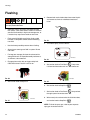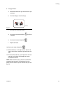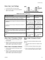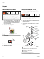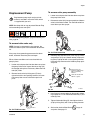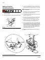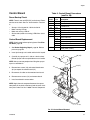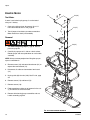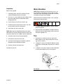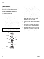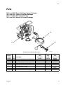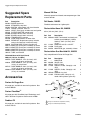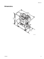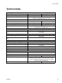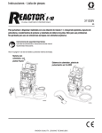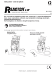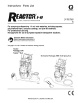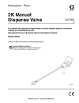
1
Instructions - Parts
Portable Plural Component Sprayer
E-8p
3A1602G
EN
For spraying 1:1 mix ratio formulated no-heat polyurethane foams and dispensing 1:1 mix
ratio polyurea joint-fill materials. For professional use only. Not approved for use in
European explosive atmosphere locations.
2000 psi (14 MPa, 138 bar) Maximum Working Pressure
See page 3 for a list of models.
Important Safety Instructions
Read all warnings and instructions in all
supplied manuals. Save all instructions.
TI17120a
Contents
Systems . . . . . . . . . . . . . . . . . . . . . . . . . . . . . . . . . . 3
Proportioners . . . . . . . . . . . . . . . . . . . . . . . . . . . . . . 3
Related Manuals . . . . . . . . . . . . . . . . . . . . . . . . . . . 3
Warnings . . . . . . . . . . . . . . . . . . . . . . . . . . . . . . . . . 4
Important Two-Component Material Information . 7
Isocyanate Conditions . . . . . . . . . . . . . . . . . . . . . 7
Material Self-ignition . . . . . . . . . . . . . . . . . . . . . . 7
Keep Components A and B Separate . . . . . . . . . 7
Moisture Sensitivity of Isocyanates . . . . . . . . . . . 7
Foam Resins with 245 fa Blowing Agents . . . . . . 7
Changing Materials . . . . . . . . . . . . . . . . . . . . . . . 8
Overview . . . . . . . . . . . . . . . . . . . . . . . . . . . . . . . . . . 8
Component Identification . . . . . . . . . . . . . . . . . . . . 9
Controls and Indicators . . . . . . . . . . . . . . . . . . . . 10
Setup . . . . . . . . . . . . . . . . . . . . . . . . . . . . . . . . . . . . 11
Location . . . . . . . . . . . . . . . . . . . . . . . . . . . . . . 11
Electrical Requirements . . . . . . . . . . . . . . . . . . 11
Grounding . . . . . . . . . . . . . . . . . . . . . . . . . . . . . 11
Lock/Unlock Handle . . . . . . . . . . . . . . . . . . . . . 12
Install 38 mm Spout Adapter . . . . . . . . . . . . . . . 12
Install Desiccant Dryers . . . . . . . . . . . . . . . . . . 12
Install Optional Recirculation Kit . . . . . . . . . . . . 13
Connect Fluid Hoses . . . . . . . . . . . . . . . . . . . . . 14
Connect Gun to Air Hose
(Air Operated Guns Only) . . . . . . . . . . . . . . 14
Connect Main Air Supply . . . . . . . . . . . . . . . . . 14
Flush Before Using Equipment . . . . . . . . . . . . . 14
Fill Wet-cups . . . . . . . . . . . . . . . . . . . . . . . . . . . 16
Install Pail Heaters . . . . . . . . . . . . . . . . . . . . . . 16
Recirculate Material . . . . . . . . . . . . . . . . . . . . . 16
Purge Air and Flush Fluid . . . . . . . . . . . . . . . . . 17
Connect Fluid Inlet Tubes . . . . . . . . . . . . . . . . . 18
Spraying . . . . . . . . . . . . . . . . . . . . . . . . . . . . . . . . . 19
Pressure Relief Procedure . . . . . . . . . . . . . . . . . . 20
Shutdown . . . . . . . . . . . . . . . . . . . . . . . . . . . . . . . . 20
Maintenance . . . . . . . . . . . . . . . . . . . . . . . . . . . . . . 21
Flushing . . . . . . . . . . . . . . . . . . . . . . . . . . . . . . . . . 22
Troubleshooting . . . . . . . . . . . . . . . . . . . . . . . . . . . 24
Status Codes . . . . . . . . . . . . . . . . . . . . . . . . . . 24
Troubleshooting Chart . . . . . . . . . . . . . . . . . . . . 27
2
Repair . . . . . . . . . . . . . . . . . . . . . . . . . . . . . . . . . . . 30
Before Beginning Repair . . . . . . . . . . . . . . . . . . 30
Recirculation/Spray Valves . . . . . . . . . . . . . . . . 30
Displacement Pump . . . . . . . . . . . . . . . . . . . . . 31
Replace Function Knob/Potentiometer . . . . . . . 32
Control Board . . . . . . . . . . . . . . . . . . . . . . . . . . 33
Pressure Transducers . . . . . . . . . . . . . . . . . . . . 35
Drive Housing . . . . . . . . . . . . . . . . . . . . . . . . . . 35
Cycle Counter Switch Replacement . . . . . . . . . 37
Electric Motor . . . . . . . . . . . . . . . . . . . . . . . . . . 38
Motor Brushes . . . . . . . . . . . . . . . . . . . . . . . . . . 39
Fan . . . . . . . . . . . . . . . . . . . . . . . . . . . . . . . . . . 39
Spout Adapter . . . . . . . . . . . . . . . . . . . . . . . . . . 40
Parts . . . . . . . . . . . . . . . . . . . . . . . . . . . . . . . . . . . . 41
Suggested Spare Replacement Parts . . . . . . . . . 50
Accessories . . . . . . . . . . . . . . . . . . . . . . . . . . . . . . 50
Dimensions . . . . . . . . . . . . . . . . . . . . . . . . . . . . . . . 51
Technical Data . . . . . . . . . . . . . . . . . . . . . . . . . . . . 53
Graco Standard Warranty . . . . . . . . . . . . . . . . . . . 54
3A1602G
Systems
Systems
Part
Maximum Working
Pressure,
psi (MPa, var)
Proportioner
(see
Proportioners)
Hose
Part
Gun Model
Length
Model
Fusion™
Part
AP9082
2000 (14, 140)
259082
24M653
50 (15.2)
CS9082
P29082
AP9083
2000 (14, 140)
2000 (14, 140)
2000 (14, 140)
259082
259082
259083
24M653
24M653
24M653
50 (15.2)
50 (15.2)
50 (15.2)
Fusion™ Air Purge
CS00RD
GCP2R0
246100
CS9083
P29083
24R151
24R154
2000 (14, 140)
2000 (14, 140)
2000 (14, 140)
2000 (14, 140)
259083
259083
259082
259083
24M653
24M653
24R823
24R823
50 (15.2)
50 (15.2)
35 (10.7)
35 (10.7)
Fusion™ CS
Probler P2
Manual 2K
Manual 2K
CS00RD
GCP2R0
24R021
24R021
Air Purge
Fusion™
CS
Probler P2
246100
Proportioners
The model no., series letter, and serial no. are located on the back of the Reactor E-8p™.
Part
★259082
259083
*
Volts
120 V
240 V
* Electrical
Connection
(motor only)
Application
15 A cord
10 A cord
No-heat polyurethane foam.
Polyurea joint-fill materials.
See page 11 for detailed electrical requirements.
Maximum Working Pressure,
psi (MPa, bar)
2000 (14, 140)
★ Approvals:
9902471
Conforms to ANSI/UL
Std. 73 Certified to
CAN/CSA Std.
C22.2 No. 68
Related Manuals
Manuals are available at www.graco.com.
Manual
313123
309550
Description
Displacement Pump Repair-Parts
312666
Fusion™
3A1602G
Fusion™ Air Purge Spray Gun Instruction-Parts
CS Spray Gun Instruction-Parts
Manual
313213
332198
Description
Probler® P2 Spray Gun Instruction-Parts
Joint Fill Gun Instructions-Parts
NOTE: The pail heaters are shipped with the manual
supplied by their manufacturer.
3
Warnings
Warnings
The following warnings are for the setup, use, grounding, maintenance, and repair of this equipment. The exclamation point symbol alerts you to a general warning and the hazard symbols refer to procedure-specific risks. When
these symbols appear in the body of this manual, refer back to these Warnings. Product-specific hazard symbols and
warnings not covered in this section may appear throughout the body of this manual where applicable.
WARNING
ELECTRIC SHOCK HAZARD
This equipment must be grounded. Improper grounding, setup, or usage of the system can cause electric
shock.
• Turn off and disconnect power cord before servicing equipment.
• Use only grounded electrical outlets.
• Use only 3-wire extension cords.
• Ensure ground prongs are intact on power and extension cords.
• Do not expose to rain. Store indoors.
TOXIC FLUID OR FUMES HAZARD
Toxic fluids or fumes can cause serious injury or death if splashed in the eyes or on skin, inhaled, or
swallowed.
• Read MSDSs to know the specific hazards of the fluids you are using.
• Store hazardous fluid in approved containers, and dispose of it according to applicable guidelines.
• Always wear chemically impermeable gloves when spraying, dispensing, or cleaning equipment.
PERSONAL PROTECTIVE EQUIPMENT
You must wear appropriate protective equipment when operating, servicing, or when in the operating area
of the equipment to help protect you from serious injury, including eye injury, hearing loss, inhalation of
toxic fumes, and burns. This equipment includes but is not limited to:
• Protective eyewear, and hearing protection.
• Respirators, protective clothing, and gloves as recommended by the fluid and solvent manufacturer.
SKIN INJECTION HAZARD
High-pressure fluid from gun, hose leaks, or ruptured components will pierce skin. This may look like just
a cut, but it is a serious injury that can result in amputation. Get immediate surgical treatment.
• Do not spray without tip guard and trigger guard installed.
• Engage trigger lock when not spraying.
• Do not point gun at anyone or at any part of the body.
• Do not put your hand over the spray tip.
• Do not stop or deflect leaks with your hand, body, glove, or rag.
• Follow the Pressure Relief Procedure when you stop spraying and before cleaning, checking, or
servicing equipment.
• Tighten all fluid connections before operating the equipment.
• Check hoses and couplings daily. Replace worn or damaged parts immediately.
4
3A1602G
Warnings
WARNING
FIRE AND EXPLOSION HAZARD
Flammable fumes, such as solvent and paint fumes, in work area can ignite or explode. To help prevent
fire and explosion:
• Use equipment only in well ventilated area.
• Eliminate all ignition sources; such as pilot lights, cigarettes, portable electric lamps, and plastic drop
cloths (potential static arc).
• Keep work area free of debris, including solvent, rags and gasoline.
• Do not plug or unplug power cords, or turn power or light switches on or off when flammable fumes are
present.
• Ground all equipment in the work area. See Grounding instructions.
• Use only grounded hoses.
• Hold gun firmly to side of grounded pail when triggering into pail.
• If there is static sparking or you feel a shock, stop operation immediately. Do not use equipment until
you identify and correct the problem.
• Keep a working fire extinguisher in the work area.
PRESSURIZED ALUMINUM PARTS HAZARD
Use of fluids that are incompatible with aluminum in pressurized equipment can cause serious chemical
reaction and equipment rupture. Failure to follow this warning can result in death, serious injury, or
property damage.
• Do not use 1,1,1-trichloroethane, methylene chloride, other halogenated hydrocarbon solvents or
fluids containing such solvents.
• Many other fluids may contain chemicals that can react with aluminum. Contact your material supplier
for compatibility.
EQUIPMENT MISUSE HAZARD
Misuse can cause death or serious injury.
• Do not operate the unit when fatigued or under the influence of drugs or alcohol.
• Do not exceed the maximum working pressure or temperature rating of the lowest rated system
component. See Technical Data in all equipment manuals.
• Use fluids and solvents that are compatible with equipment wetted parts. See Technical Data in all
equipment manuals. Read fluid and solvent manufacturer’s warnings. For complete information about
your material, request MSDS from distributor or retailer.
• Do not leave the work area while equipment is energized or under pressure. Turn off all equipment and
follow the Pressure Relief Procedure when equipment is not in use.
• Check equipment daily. Repair or replace worn or damaged parts immediately with genuine
manufacturer’s replacement parts only.
• Do not alter or modify equipment.
• Use equipment only for its intended purpose. Call your distributor for information.
• Route hoses and cables away from traffic areas, sharp edges, moving parts, and hot surfaces.
• Do not kink or over bend hoses or use hoses to pull equipment.
• Keep children and animals away from work area.
• Comply with all applicable safety regulations.
3A1602G
5
Warnings
WARNING
MOVING PARTS HAZARD
Moving parts can pinch, cut or amputate fingers and other body parts.
• Keep clear of moving parts.
• Do not operate equipment with protective guards or covers removed.
• Pressurized equipment can start without warning. Before checking, moving, or servicing equipment,
follow the Pressure Relief Procedure and disconnect all power sources.
BURN HAZARD
Equipment surfaces and fluid that’s heated can become very hot during operation. To avoid severe
burns:
• Do not touch hot fluid or equipment.
6
3A1602G
Important Two-Component Material Information
Important Two-Component Material Information
Isocyanate Conditions
Spraying or dispensing materials containing
isocyanates creates potentially harmful mists, vapors,
and atomized particulates.
Read material manufacturer’s warnings and material
MSDS to know specific hazards and precautions
related to isocyanates.
Prevent inhalation of isocyanate mists, vapors, and
atomized particulates by providing sufficient
ventilation in the work area. If sufficient ventilation is
not available, a supplied-air respirator is required for
everyone in the work area.
To prevent contact with isocyanates, appropriate
personal protective equipment, including chemically
impermeable gloves, boots, aprons, and goggles, is
also required for everyone in the work area.
Moisture Sensitivity of
Isocyanates
Isocyanates (ISO) are catalysts used in two component
foam and polyurea coatings. ISO will react with moisture
(such as humidity) to form small, hard, abrasive crystals,
which become suspended in the fluid. Eventually a film
will form on the surface and the ISO will begin to gel,
increasing in viscosity. If used, this partially cured ISO
will reduce performance and the life of all wetted parts.
NOTE: NOTE: The amount of film formation and rate of
crystallization varies depending on the blend of ISO, the
humidity, and the temperature.
To prevent exposing ISO to moisture:
•
Always use a sealed container with a desiccant
dryer in the vent, or a nitrogen atmosphere. Never
store ISO in an open container.
•
Keep the felt washers in the pump wet cups saturated with Graco ISO pump oil, Part No. 217374.
The lubricant creates a barrier between the ISO and
the atmosphere.
•
Use moisture-proof hoses specifically designed for
ISO, such as those supplied with your system.
•
Never use reclaimed solvents, which may contain
moisture. Always keep solvent containers closed
when not in use.
•
Never use solvent on one side if it has been contaminated from the other side.
•
Always lubricate threaded parts with ISO pump oil
or grease when reassembling.
•
Always park pumps when you shutdown. See
page 20.
Material Self-ignition
Some materials may become self-igniting if applied
too thickly. Read material manufacturer’s warnings
and material MSDS.
Keep Components A and B
Separate
Cross-contamination can result in cured material in
fluid lines which could cause serious injury or
damage equipment. To prevent cross-contamination
of the equipment’s wetted parts, never interchange
component A (isocyanate) and component B (resin)
parts.
Foam Resins with 245 fa
Blowing Agents
Some foam blowing agents will froth at temperatures
above 90°F (33°C) when not under pressure, especially
if agitated.
3A1602G
7
Overview
Changing Materials
•
When changing materials, flush the equipment multiple times to ensure it is thoroughly clean.
•
Check with your material manufacturer for chemical
compatibility.
•
Most materials use ISO on the A side, but some use
ISO on the B side.
•
Epoxies often have amines on the B (hardener)
side. Polyureas often have amines on the B (resin)
side.
Overview
The Reactor E-8p is a portable, electric-powered, 1:1
mix ratio proportioner. It is for use with formulated
no-heat polyurethane foams that may be applied with
impingement mix spray guns and for use with polyurea
joint fill materials that may be applied with static mix
guns.
Severe duty, positive displacement reciprocating piston
pumps meter fluid flow to the gun for mixing and applying. When set to recirculation mode, the Reactor E-8p
will circulate fluids back to the supply pails.
An electronic processor controls the motor, monitors
fluid pressures, and alerts the operator if errors occur.
See STATUS Indicator, page 10, for further information.
The Reactor E-8p has two recirculation speeds: slow
and fast, and an adjustable pressure output.
Slow Recirculation
•
Use for pump priming.
Fast Recirculation
•
•
Use for flushing.
Use for pump priming.
Pressure Adjust
Automatically maintains selected pressure output for
spraying.
8
3A1602G
Component Identification
Component Identification
C
BACK VIEW
L
FRONT VIEW
J
Q
A
N
F
B
D
L
E
Q
P
M
G
H
TI17121a
FIG. 1: Component Identification
Key:
A
B
C
D
E
F
G
H
J
K
L
M
N
P
Q
Pump A
Pump B
Fluid Pressure Gauges
Recirc/Spray and Overpressure Relief Valves
Control Panel
Electric Motor and Drive Housings
Hose Bundle
Spray Gun
Recirculation Tubes
Air Line Inlet (quick-disconnect fitting)
Outlet Hose Connections
Power Cord
Lift Ring/Handle/Hose Rack
Fluid Inlet Tubes
Desiccant Dryers
3A1602G
9
Controls and Indicators
Controls and Indicators
Status Indicator
Motor/Pump Control Function Knob
Power
Switch
Status
Codes
+
-
I
-
-
TI17123b
FIG. 2: Controls and Indicators
Power Switch
STATUS Indicator
Powers the Reactor E-8p on and off.
Indicates system status, including power and error
codes.
Motor/Pump Control Function Knob
•
Indicator steady on: power switch is turned on.
•
Indicator blinking: If an error occurs, the status indicator light will blink one to seven times to indicate a
specific status code, pause, and then repeat. The
following table provides a brief description of each
status code. For more detailed information and corrective action, see Status Codes on page 24.
Use knob to select desired function.
Icon
Setting
Function
Stop/Park
Stops motor and automatically parks pumps.
Slow Recirc
Slow recirculation speed.
Fast Recirc
Fast recirculation speed.
Static Mix
Spray
Use fluid pressure settings
1-5 to dispense polyurea
joint-fill materials through a
static mixer.
Use fluid pressure settings
6-10 to spray polyurethane
foam.
Table 1: Status Codes
(also located on front of Reactor)
Code
Code Name
1
Pressure imbalance between A and B sides
2
Unable to maintain pressure setpoint
3
Pressure transducer A failure
4
Pressure transducer B failure
5
Excessive current draw
6
High motor temperature
7
No cycle counter switch input
NOTE: The default is to shut down if a status code indication occurs. Codes 1 and 2 may be set to disable
automatic shutdown if desired; see page 25. You cannot
set the other codes.
10
3A1602G
Setup
Setup
Location
•
•
Grounding
The Reactor E-8p should always be used on a level
surface.
Do not expose the Reactor E-8p to rain.
Electrical Requirements
The equipment must be grounded. Grounding
reduces the risk of static and electric shock by
providing an escape wire for the electrical current due
to static build up or in the event of a short circuit.
Reactor E-8p: grounded through power cord.
Improper wiring may cause electric shock or other
serious injury if work is not performed properly. Have
a qualified electrician perform any electrical work. Be
sure your installation complies with all National, State
and Local safety and fire codes.
•
Required power source: single dedicated circuit that
is rated at a minimum of 15A.
NOTE: Cords must be 3-conductor grounded, rated for
your environment.
•
Power cord connector (120V):
Spray gun: ground through connection to a properly
grounded fluid hose and grounded Reactor E-8p. Do not
operate without at least one grounded fluid hose.
Fluid supply container: follow local code.
Object being sprayed: follow local code.
Solvent pails used when flushing: follow local code.
Use only conductive metal pails, placed on a grounded
surface. Do not place the pail on a nonconductive surface, such as paper or cardboard, which interrupts
grounding continuity.
One NEMA 5-15T
•
Generator (if used): follow your local code and manufacturer’s recommendations. Start and stop the generator with power cord(s) disconnected.
Power cord connector (240 V):
One IEC 320, with two local adapters
Euro CEE74 Adapter
To maintain grounding continuity when flushing or
relieving pressure: hold metal part of the spray gun
firmly to the side of a grounded metal pail, then trigger
the gun.
Australia/China Adapter
•
Extension cord requirements:
Required Wire Size
Up to 50 ft (15 m)
Up to 100 ft (30 m)
AWG 14
AWG 12
3A1602G
11
Setup
Lock/Unlock Handle
Install 38 mm Spout Adapter
Lock the handle when the sprayer is moved, laid on its
side, or turned upside down.
The sprayer is supplied with a 40 mm spout adapter.
Install 38 mm spout adapters if necessary.
Unlock
1. Loosen containment knob.
To unlock the handle, remove lanyard and locking pin
from cart handle. Pull on handle to extend cart handle
and move sprayer.
2. Remove suction tube caps and place in containment
tray.
3. For installation instructions, see Spout Adapter,
page 40.
40 mm
Black
38 mm
Silver
ti17513a
FIG. 3
ti18063a
FIG. 5: Spout Adapters
Lock
To lock the handle, press down handle pins and slide
cart handle through tubes. Insert pin through cart handle and lock with lanyard.
Install Desiccant Dryers
1. Use needle nose pliers to remove two plugs (P)
from the dryer (73).
2. Remove plug from adapter housing (57).
3. Screw the dryer into the adapter housing (57) handtight only. Do not overtighten.
57
P
73
P
ti17475a
FIG. 6: Desiccant Dryer Installation
ti17514a
FIG. 4
12
3A1602G
Setup
Install Optional Recirculation Kit
552
Use Hose Recirculation Kit 24M654 to help evenly distribute heat when using supplemental heaters and circulate material through the fluid manifold, out to the gun,
and back to the material supply container. See Accessories, page 50.
509
510
Apply thread sealant to all non-swiveling pipe threads.
NOTICE
To prevent cross-contamination of fluids and equipment parts, never interchange component A (isocyanate) and component B (resin) parts or containers.
B Side
A Side
507
507
1. Relieve pressure. See Pressure Relief Procedure,
page 20.
2. Flush. See page Flushing, page 22.
508
508
3. Remove fluid tubes (36).
507
508
515
33
34
511
33
551
218
36
218
515
501
510
WLD
FIG. 8
36
34
7. Install plugs (552).
8. Loosen pump lock nut (218) by hitting firmly with
right-to-left with a non-sparking hammer. Rotate
pump until there is enough space to install pressure
gauges. If the transducer cable is tight, remove bottom cover and cut cable ties. See FIG. 56, page 32.
509
33
ti18824a
FIG. 7
4. Place a wrench on the pressure transducer manifold
(33) and remove the adapters (34). Set A and B side
adapters aside.
5. Remove fittings (509) and (510). Remove two swivel
fittings (515) and elbow fittings (511) from tee fitting
(508). Remove tee fittings and gauges (507) from
manifold (501). Set A and B side parts aside. Elbow
fittings (511) are not used with recirculation setup.
6. Install 1/4 npt x -6 JIC adapter fitting (510) in the B
side fluid manifold outlet port. Install 1/4 npt x -5 JIC
fitting (509) in the A side fluid manifold outlet port.
3A1602G
9. Install A and B side tee fittings (508) in the pressure
transducer manifolds (33). Install adapter fitting
(551) and adapter fitting (34) in tee fittings (508).
10. Install gauges (507) in tee fittings (508).
NOTE: Ensure that there is enough space to dispense
Graco ISO pump oil in the wet cup through the pump
cover.
11. Tighten locknut (218) by hitting firmly with a
non-sparking hammer.
12. Install fluid tubes (36).
13
Setup
Connect Fluid Hoses
Connect Main Air Supply
Connect fluid supply hoses to outlet hose connections
(FIG. 9 and FIG. 10). Red hoses for component A (ISO),
blue for component B (RES). Fittings are sized to prevent connection errors. Connect other end of hoses to A
and B inputs of gun.
NOTE: The Reactor E-8p requires 4 scfm
(0.112 m3/min) compressed air for the air operated
spray guns to work correctly.
NOTE: If using the Recirculation Hose Kit 24M654, connect hoses to Recirculation Gun Manifold Kit 249523.
See FIG. 10.
Connect the main air supply to the quick disconnect fitting on the unit. The air supply hose must be at least
5/16 in. (8 mm) ID up to 50 ft (15 m) or 3/8 in. (10 mm)
ID up to 100 ft (30 m).
Flush Before Using Equipment
Connect Gun to Air Hose
(Air Operated Guns Only)
Connect gun air hose to the gun air input and to the air
filter outlet. If you are using more than one hose bundle,
join the air hoses with the nipple provided with the hose
bundle.
The equipment was tested with lightweight oil, which is
left in the fluid passages to protect parts. To avoid contaminating your fluid with oil, flush the equipment with a
compatible solvent before using the equipment. See
Flushing, page 22.
A (ISO)
A (ISO)
B (RES)
Air
Compressed
Air Line
B (RES)
ti17122a
FIG. 9: Hose and Air Connections
14
3A1602G
Setup
A Recirculation
A (ISO)
B Recirculation
A (ISO)
Air
B (RES)
Compressed
Air Line
B (RES)
Recirculation Gun Manifold Kit 249523
(only compatible with Fusion Air Purge Gun)
601
604
605
607
607
605
604
602
603
2
TI7134A
FIG. 10: Hose and Air Connections - Recirculation Hose Kit 24M654
3A1602G
15
Setup
Fill Wet-cups
Recirculate Material
Keep the felt washers in the pump wet-cups saturated
with Graco ISO pump oil, Part No. 217374. The lubricant
creates a barrier between the ISO and the atmosphere.
The standard system circulates material from the fluid
manifold back to the supply container. To circulate material from the gun back to the material supply container,
purchase and install Hose Recirculation Kit 24M654.
See Install Optional Recirculation Kit on page 13.
The pump rod and connecting rod move during
operation. Moving parts can cause serious injury
such as pinching or amputation. Keep hands and
fingers away from the wet-cup during operation. Shut
off power before filling the wet-cup.
1. Insert inlet tubes into pails. See Connect Fluid
Inlet Tubes, page 18.
2. Set function knob to Stop/Park.
Fill wet-cups through the slots in the plate, or remove a
screw and swing the plate to the side.
+
-
TI17127b
Slots
FIG. 12
TI17124a
3. Plug in power cord.
FIG. 11: Fill Wet Cup
4. Turn on power.
O
O
Follow all warnings and instructions from both the
fluid manufacturer technical data sheet and the pail
heater installation manual.
I
I
Install Pail Heaters
TI17134a
FIG. 13
5. Set the Recirc/Spray valves to Recirc.
If the material viscosity at room temperature is greater
than 2000 centipoise the pump may not siphon feed
on-ratio. Purchase and install the optional flexible pail
heaters so the material can be warmed, resulting in a
lower viscosity and enabling the pump to properly
siphon feed. See Accessories on page 50.
Install and operate according to the included pail heater
manufacturer’s installation manual.
16
TI17133a
FIG. 14
3A1602G
Setup
6. Set function knob to Slow Recirc
or Fast Recirc
Purge Air and Flush Fluid
.
+
-
OR
1. Insert inlet tubes into pails of solvent.
+
-
TI17128b
FIG. 15
7. When material exits both recirculation tubes, set the
function knob to Stop/Park
.
TI17126a
8. Set the Recirc/Spray valves to Spray.
FIG. 17
2. Insert recirculation tubes into waste containers.
3. Set function knob to Stop/Park.
TI17132a
FIG. 16
+
-
TI17127b
FIG. 18
4. Plug in power cord.
O
O
I
I
5. Turn on power.
TI17134a
FIG. 19
6. Set the Recirc/Spray valves to Recirc.
TI17133a
FIG. 20
3A1602G
17
Setup
7. Set function knob to Slow Recirc
or Fast Recirc
Connect Fluid Inlet Tubes
.
1. Loosen containment knob.
+
-
OR
+
-
TI17128b
FIG. 21
8. When clean solvent exits both recirculation tubes,
set the function knob to Stop/Park
2. Remove suction tube caps and place in containment
tray.
3. Insert each fluid inlet tube through the pour spout on
the appropriate five-gallon pail. Tighten the ring to
the pour spout.
.
9. Insert inlet tubes into pails. See Connect Fluid
Inlet Tubes, page 18.
Ring
10. Set the Recirc/Spray valves to Spray.
TI17132a
FIG. 22
11. Run until material exits gun manifold.
TI17125a
FIG. 23
NOTICE
To prevent cross-contamination of fluids and equipment parts, never interchange component A (isocyanate) and component B (resin) parts or containers.
Label one pail “A” and the other “B”, using the red and
blue labels provided. Always double check which
material you have before placing fluid inlet tube into
the pail.
NOTE: Use a drill and mixing blade to mix filled or separated materials in the pail before placing fluid inlet tube
into the pail.
18
3A1602G
Spraying
Spraying
NOTE: For air operated guns, air is supplied to spray
gun with gun piston safety lock engaged and gun fluid
manifold valves A and B closed (if present).
NOTE: If using the Manual 2K gun, refer to the Manual
2K gun instruction manual.
6. Check fluid pressure gauges to ensure proper pressure balance. If imbalanced, reduce pressure of
higher component by slightly turning Recirc/Spray
valve for that component toward Recirc, until
gauges show balanced pressures. The pressure
imbalance alarm (Status Code 1) is inactive for 10
seconds after entering spray pressure mode, to
allow time to balance pressures.
In this example, the B
side pressure is
higher, so use the B
side valve to balance
pressures.
FIG. 24
TI17137a
FIG. 28
1. Set function knob to Stop/Park.
NOTE: Watch gauges for 10 seconds to ensure pressure holds on both sides and pumps are not moving.
7. Open gun fluid manifold valves A and B (impingement mix guns only).
+
-
TI17127b
FIG. 25
2. Engage piston safety lock.
3. Open gun manifold.
FIG. 29
4. Set Recirc/Spray valves to Spray.
NOTE: On impingement guns, never open fluid manifold valves or trigger gun if pressures are imbalanced.
8. Disengage piston safety lock.
TI17132a
FIG. 26
5. Turn the pressure control knob to the right until fluid
pressure gauges show desired pressure.
NOTE: It is desirable to use lower pressure for joint filling applications.
+
-
FIG. 30
9. Test spray onto cardboard or plastic sheet. Verify
that material fully cures in the required length of
time, and is the correct color. Adjust pressure and
temperature to get desired results. Equipment is
ready to spray.
TI17129b
FIG. 27
3A1602G
19
Pressure Relief Procedure
Pressure Relief
Procedure
Shutdown
NOTE: For longer breaks (more than 10 minutes), use
the following procedure. If you will be shut down for
more than three days, perform the Flushing procedure,
page 22, first.
Trapped air can cause the pump to cycle
unexpectedly, which could result in serious injury
from splashing or moving parts.
NOTE: If using the Manual 2K gun, refer to the Manual
2K gun instruction manual.
1. Engage piston safety lock.
NOTE: If using the Manual 2K gun, refer to the Manual
2K gun instruction manual.
1. Follow Pressure Relief Procedure.
2. Close gun fluid valves A and B. Doing this will keep
the internal parts of the gun cleaner and prevent
crossover.
FIG. 31
FIG. 34
2. Set function knob to Stop/Park.
I
+
O
O
3. Shut off power.
O
I
-
TI17135a
TI17127b
FIG. 32
FIG. 35
3. Turn Recirc/Spray valves to Recirc. Fluid will be
returned to material pails. Pumps will move to the
bottom of their stroke. Ensure gauges drop to 0.
4. Loosen rings from pour spouts and remove fluid
inlet tubes from pails. Allow residual fluid to drain
into the appropriate pail.
Ring
TI17133a
FIG. 33
TI17125a
FIG. 36
20
3A1602G
Maintenance
5. Use solvent to wipe down fluid inlet tubes.
6. Install suction tube caps on each fluid inlet tube and
rest in the containment tray. Tighten the containment knob to press the bracket against the fluid inlet
tubes.
TI17458a
Maintenance
•
Check pump wet-cups fluid level daily. Refer to Fill
Wet-cups, page 16.
•
Do not overtighten packing nut/wet-cup. Throat
u-cup is not adjustable.
•
Keep component A from exposure to moisture in
atmosphere, to prevent crystallization.
•
Containment
Knob
Check desiccant filters weekly. Filter is blue when
fresh, and turns pink when saturated.
•
Generally, flush if you will shutdown for more than
three days. Flush more often if material is moisture
sensitive and humidity is high in the storage area, or
if material may separate or settle out over time.
Caps
•
Close gun fluid valves A and B when not spraying.
Doing this will keep the internal parts of the gun
cleaner and prevent crossover. Clean gun mix
chamber ports and check valve screens regularly.
See spray gun manual.
FIG. 37
7. Refer to your separate spray gun manual to perform
the gun shutdown procedure.
8. Wrap hoses around sprayer.
9. Disconnect power cord before moving.
FIG. 39
TI17459a
FIG. 38
3A1602G
•
Always grease the gun after use until purge air carries grease mist out the front of the gun. Use Part
No. 117773 Grease. See spray gun manual.
•
Always grease the inlet tube spout adapters after
use. Use Part No. 117773 Grease and grease gun
supplied with spray gun.
•
Remove any material from containment tray with
solvent.
21
Flushing
Flushing
3. Remove both recirculation tubes from material pails
and secure each one to a dedicated waste container.
Flush equipment only in a well-ventilated area. Do
not spray flammable fluids.
•
Generally, flush if you will be shut down for more
than 3 days. Flush more often if material is moisture
sensitive and humidity is high in the storage area, or
if material may separate or settle out over time.
•
Flush out old fluid with new fluid, or flush out old
fluid with a compatible solvent before introducing
new fluid.
•
Use the lowest possible pressure when flushing.
•
Always leave some type of fluid in system. Do not
use water.
•
For long term storage, flush out the solvent with a
storage fluid such as Bayer Mesamoll plasticizer or,
at minimum, clean motor oil.
TI17126a
FIG. 42
4. Turn Recirc/Spray valves to Recirc.
TI17133a
FIG. 43
1. Engage piston safety lock or trigger safety lock.
Close fluid valves A and B. Leave air on.
5. Set function knob to Fast Recirc
. Pump mate-
rial from fluid inlet tubes until no more comes out.
+
-
FIG. 40
TI17130b
FIG. 44
2. Set function knob to Stop/Park.
6. Set function knob to Stop/Park
.
7. Set function knob to Fast Recirc
. Pump solvent
through system into waste containers.
+
-
8. When nearly clear solvent exits the fluid inlet tubes,
TI17127b
FIG. 41
set function knob to Stop/Park
.
NOTE: To flush the spray gun, refer to your separate
spray gun instruction manual.
22
3A1602G
Flushing
9. Purge gun hoses.
a. Disconnect hoses from gun and secure to a pail
of solvent.
b.
Turn Recirc/Spray valve A to Spray.
TI17136a
FIG. 45
c.
Open gun into waste container A.
d. Set function knob to Slow Recirc
until hose
is flushed.
e. Set function knob to Stop/Park
f.
.
Repeat for B side.
10. Set function knob to Stop/Park
.
11. Solvent flushing is a two step process. Go back to
step 3, drain solvent, and flush again with fresh solvent.
12. Place fluid inlet tubes in a pail of plasticizer or clean
motor oil and circulate fluid through the system.
Leave fluid in the unit.
NOTE: Never leave the unit dry unless it has been disassembled and cleaned. If fluid residue dries in the
pumps, the ball checks may stick the next time you use
the unit.
3A1602G
23
Troubleshooting
Troubleshooting
Status Codes
Determine the status code by counting the number of
times the status indicator blinks.
2. Reduce pressure of higher component by slightly
turning Recirc/Spray valve for that component
toward Recirc, until gauges show balanced pressures.
In this example, B side
pressure is higher, so
use the B side valve to
balance pressures.
STATUS Indicator
TI17137a
FIG. 47
I
-
NOTE: Turn Recirc/Spray valve only enough to balance
pressure. If turned completely, all pressure will bleed off.
3. Check fluid inlet strainers and fluid filters at gun.
TI17123b1
FIG. 46
Status Code 1: Pressure Imbalance
NOTE: The unit does not check for pressure imbalance
at setpoints less than 250 psi (1.75 MPa, 17.5 bar). The
unit does not check for pressure imbalance for 10 seconds after entering pressure mode.
Unit senses pressure imbalance between components
A and B, and warns or shuts down, depending on settings of DIP switches 1 and 2. To turn off automatic shutdown and/or tighten pressure tolerances for status code
1, see Status Code 1 and 2 Settings.
1. Check fluid supply of lower pressure component
and refill if necessary.
24
Status Code 2: Pressure Deviation
from Setpoint
NOTE: The unit does not check for pressure deviation at
setpoint less than 400 psi (2.8 MPa, 28 bar).
Unit senses pressure deviation from setpoint, and warns
or shuts down, depending on settings of DIP switches 3
and 4. If equipment cannot maintain enough pressure
for a good mix at the gun, try using a smaller mix chamber or nozzle.
To turn off automatic shutdown and/or tighten pressure
tolerances for status code 2, see Status Code 1 and 2
Settings.
3A1602G
Troubleshooting
Status Code 1 and 2 Settings
OFF
1
2
3
4
1. Locate switch SW2 on the control board.
2. Set the four DIP switches to the desired positions.
See FIG. 48 and Table 2.
TI7023a
1
2
3
4
ON
(Default)
TI7024a
FIG. 48. DIP Switch (SW2) Settings
Table 2: Status Code 1 and 2 Settings
DIP Switch and Function
Left
DIP Switch 1
If selected, causes shutdown or displays a warning if the pres- WARNING
sure imbalance exceeds selection made in DIP Switch 2
Right (default setting)
SHUTDOWN
DIP Switch 2
If selected, causes shutdown if A and B pressure imbalance is 500 psi (3.5 MPa, 35
greater than
bar)
(60% if < 800 psi [5.6
MPa, 56 bar] running)
800 psi (5.6 MPa, 56
bar)
(70% if < 800 psi [5.6
MPa, 56 bar] running)
If selected, causes warning if A and B pressure imbalance is
greater than
500 psi (3.5 MPa, 35
bar)
(60% if < 800 psi [5.6
MPa, 56 bar] running)
300 psi (2.1 MPa, 21
bar)
(50% if < 800 psi [5.6
MPa, 56 bar] running)
DIP Switch 3
If selected, causes shutdown or displays a warning due to devi- WARNING
ation of pressure from setpoint exceeds selection made in DIP
Switch 4
DIP Switch 4
300 psi (2.1 MPa, 21
Causes warning if deviation of pressure from setpoint is greater bar)
(25% if < 800 psi [5.6
than
MPa, 56 bar])
Status Code 3: Transducer A Failure
1. Check transducer A electrical connections (J3) at
board, page 34.
2. Reverse A and B transducer electrical connections
at board, page 34. If error moves to transducer B
(Status Code 4), replace transducer A, page 33.
SHUTDOWN
500 psi (3.5 MPa, 35
bar)
(40% if < 800 psi [5.6
MPa, 56 bar])
Status Code 5: Excessive Current
Draw
Shut off unit and contact distributor before resuming
operation.
1. Locked rotor: motor unable to turn. Replace motor,
page 38.
Status Code 4: Transducer B Failure
2. Short on control board. Replace board, page 33.
1. Check transducer B electrical connections (J8) at
board, page 34.
3. Worn or hung up motor brush causing arching of
brush at commutator. Replace brushes, page 39.
2. Reverse A and B transducer electrical connections
at board, page 34. If error moves to transducer A
(Status Code 4), replace transducer B, page 33.
3A1602G
25
Troubleshooting
Status Code 6: High Motor
Temperature
Motor is running too hot.
1. Motor temperature too high. Reduce pressure duty
cycle, gun tip size, or move Reactor E-8p to a cooler
location. Allow 1 hour for cooling.
2. Check fan operation. Clean fan and motor housing.
Status Code 7: No Cycle Counter
Switch Input
Have not received input from cycle counter switch for 10
seconds after selecting Recirculation Mode.
1. Check cycle counter switch connection to board
(J10, pins 5, 6), page 34 (figure control module wiring connections).
2. Check that magnet (224) and cycle counter switch
(223) are in place under B side motor end cover
(227). Replace if necessary.
26
3A1602G
Troubleshooting
Troubleshooting Chart
Plug in power cord.
I
I
Motor does not operate.
Power turned on with function knob
set to a run position.
,
to reset breaker.
O
then on
O
I
Cycle Motor Power off
I
No power.
Solution
O
O
Reactor E-8p does not operate.
Cause
O
Problem
Set function knob to Stop/Park
, then select desired function.
Fan not working.
Pump output low.
One side doesn’t come up to pressure in spray mode.
3A1602G
Loose connection on control board.
Check connection at J11 (120V
models) or J4 (240V models). See
page 33.
Worn brushes.
Check both sides. Replace brushes
worn to less than 1/2 in. (13 mm),
see page 39.
Broken or misaligned brush springs.
Realign or replace, page 39.
Brushes or springs binding in brush
holder.
Clean brush holder and align brush
leads for free movement.
Shorted armature.
Replace motor, page 38.
Check motor commutator for burn
spots, black pitting, or other damage.
Remove motor. Have motor shop
resurface commutator, or replace
motor, page 38.
Failed control board.
Replace board. See page 33.
Loose fan cable.
Check that cable is connected at fan
and at J9 on control board. See
pages 39 and 33.
Defective fan.
Test and replace if necessary,
page 39.
Plugged fluid inlet strainer.
Clear, see page 21.
Plugged disposable mixer.
Clean or replace.
Leaking or plugged piston valve or
intake valve in displacement pump.
Check valves. See pump manual.
Dirty or damaged Recirc/Spray
valve.
Clean or repair, page 30.
Plugged fluid inlet strainer.
Clear, see page 21.
Pump intake valve plugged or stuck
open.
Clean pump intake valve. See
page 31.
Material is too viscous to siphon
feed.
Warm the material feed pails with
flexible band heaters. See Accessories on page 50.
27
Troubleshooting
Problem
Cause
Solution
Pressure is higher on one side
when setting pressure with function
knob.
Pump intake valve partially plugged.
Clean pump intake valve. See page
31.
Air in hose. Fluid is compressible.
Purge air from hose.
Unequal size hoses or unequal
hose construction.
Use matching hoses, or balance
pressures before spraying.
Unequal viscosities.
Check that A and B chemicals are
within the chemical manufacturer’s
specified application temperature
range.
Pressures are not balanced when
running, but pressure is generated
and holds on both strokes.
Change restrictor at mix point to
balance back pressure.
Restriction on one side.
Clean mix module or restrictor at
mix manifold.
Clean gun check valve screens.
Fluid leak in pump packing nut area.
Worn throat seals.
Replace. See pump manual.
Pressure doesn’t hold when stalled
against gun in spray mode.
Leaking Recirc/Spray valve.
Repair, page 30.
Leaking piston valve or intake valve
in displacement pump.
Repair. See pump manual.
Leaking gun shutoff.
Repair. See gun manual.
Pressure is higher on B side during
startup of recirculation, especially in
High Recirc mode.
This is normal. Component B is typically higher viscosity than component A until the material is heated
during recirculation.
No action required.
One gauge shows half as many
pulses as the other when pumps
are cycling.
Loss of pressure on downstoke.
Intake valve is leaking or not closing. Clean or replace valve; see
page 31.
Loss of pressure on upstoke.
Piston valve is leaking or not closing. Clean or replace valve or packings; see page 31.
I
I
28
O
O
,
to reset breaker.
O
then on
O
I
Cycle Motor Power off
I
Motor Power switch off.
O
Status indicator (red LED) not lit.
Loose indicator cable.
Check that cable is connected at
J10 pins 1 (red) and 2 (black) on
control board. See page 33.
Failed control board.
Replace board. See page 33.
3A1602G
Troubleshooting
Problem
A side rich; lack of B side.
B side rich; lack of A side.
3A1602G
Cause
Solution
A side gauge is low.
B side restriction downstream of
gauge. Check gun check valve
screen, mix module, or mix manifold
restrictor.
B side gauge is low.
B side material supply problem.
Check B side inlet strainer and
pump intake valve.
A side gauge is low.
A side material supply problem.
Check A side inlet strainer and
pump intake valve.
B side gauge is low.
A side restriction downstream of
gauge. Check gun check valve
screen, mix module, or mix manifold
restrictor.
29
Repair
Repair
Before Beginning Repair
Recirculation/Spray Valves
1. See Before Beginning Repair, page 30. Relieve
pressure, page 20.
Repairing this equipment requires access to parts
which may cause electric shock or other serious
injury if work is not performed properly. Have a
qualified electrician connect power and ground to
main power switch terminals, see page 11. Be sure to
shut off all power to the equipment before repairing.
1. Flush if possible, see page 22. If not possible, clean
all parts with solvent immediately after removal, to
prevent isocyanate from crystallizing due to moisture in the atmosphere.
2. Clean and inspect all parts for damage. Ensure that
the seat (503a) and gasket (503b) are positioned
inside each valve cartridge (503).
3. Apply PTFE pipe sealant to all tapered pipe threads
before reassembling.
4. Reassemble in reverse order, following all notes in
FIG. 51.
2. Set function knob to Stop/Park.
3
506
505
3
504
3
503
1
2
3
+
-
TI17127b
503a
4
503b
4
FIG. 49
501
507
3. Shut off power.
O
O
O
I
I
502
508
510
TI17135a
FIG. 50
509
4. Relieve pressure, page 20.
511
515
TI17460a
1
Torque to 250 in-lb (28 N•m).
2
Use blue threadlocker on valve cartridge threads into
manifold.
3
Apply lubricant to mating surfaces.
4
Part of item 503.
FIG. 51: Recirculation/Spray Valves
30
3A1602G
Repair
Displacement Pump
To remove entire pump assembly
Displacement pump repair and parts information is included in manual 311076, which
is supplied with your unit.
NOTE: Use drop cloth or rags to protect Reactor E-8p
and surrounding area from spills.
1. Loosen nut and press the inlet tube down away from
the pump intake valve.
2. Disconnect swivel (32) from pump outlet and loosen
swivel at the fluid manifold. Turn the fluid outlet line
out of the way of the sprayer.
See Before Beginning Repair, page 30. Relieve pressure, page 20.
To remove intake valve only
NOTE: If pump is not generating any pressure, the
intake ball check may be stuck closed with dried material.
If the pump is not generating pressure on the downstroke, intake ball check may be stuck open.
Either of these conditions can be serviced with the
pump in place.
32
3. Remove pump rod cover (222). Push clip up in back
and push pin (217) out. Loosen locknut (218) by hitting firmly right-to-left with a non-sparking hammer.
Unscrew pump. See manual 311076 for pump repair
and parts.
1. Loosen nut and press the inlet tube down away from
the pump intake valve. Inspect the two o-rings (52)
for damage and replace if necessary. Move the inlet
tube (53) aside.
2. Remove intake valve by hitting ears (E) firmly
right-to-left with a non-sparking hammer. Unscrew
from pump. See manual 313123 for repair and
parts.
ti17462a
FIG. 53: Fluid Outlet Line
1
Flat side faces up.
Tighten by hitting firmly
with non-sparking
hammer.
2
Lubricate threads with
ISO oil or grease.
217
2
D
2
C
222
218
1
2
ti17463a
FIG. 54
E
4. Install pump in reverse order of disassembly, following all notes in FIG. 54. Reconnect fluid inlet (C) and
outlet (D) lines.
52
53
ti17461a
FIG. 52: Fluid Inlet Tube
3A1602G
5. Tighten fluid outlet fitting (D), then tighten locknut
(218) by hitting firmly with a non-sparking hammer.
6. Set function knob to Slow Recirc
and prime. See page 17.
. Purge air
31
Repair
Replace Function
Knob/Potentiometer
4. Carefully lay sprayer on it’s side on a level surface.
Rotate sprayer and rest upside down on cart handle.
NOTE: Always use two people when lifting the sprayer
up on to a workbench.
1. See Before Beginning Repair, page 30. Relieve
pressure, page 20.
2. Insert pin through cart handle and lock with lanyard.
5. Remove four screws (10) and control board cover
(61) to expose the control board (12).
6. Disconnect potentiometer wires from J2 on control
board (12). See Fig 12.
7. See Fig 11. Remove two setscrews (16a) and pull
function knob (23) off potentiometer (16) shaft.
8. Remove nut (N, part of 16) and detent plate (22).
Remove potentiometer (16) and washer (87).
9. Install new potentiometer (16) in reverse order. Position potentiometer so slot (S) is horizontal. Position
knob (16) so pointer (P) faces toward the top. Install
knob on shaft so slot (S) engages alignment pin in
knob. Push knob onto shaft against detent spring
before tightening setscrews (16a).
ti17464a
FIG. 55
3. Carefully lay sprayer on its side on a level surface.
10. Reconnect potentiometer wires to J2 as shown in
Fig 12.
10
61
16
12
S
22
87
16a
N
23
P
ti17465a
FIG. 56. Function Knob/Potentiometer
32
3A1602G
Repair
Control Board
Power Bootup Check
NOTE: There is one red LED (D11) on the board. Power
must be on to check. See FIG. 58 for location. Function
is:
•
•
•
•
Startup: 1 blink for 60 Hz, 2 blinks for 50 Hz.
Motor running: LED on.
Motor not running: LED off.
Status code (motor not running): LED blinks status
code
Table 3: Control Board Connectors
(see FIG. 58)
Board
Jack
J1
J2
J3
J4
J7
J8
J9
J10
Pin
n/a
n/a
n/a
n/a
1, 2
n/a
n/a
1, 2
3, 4
5, 6
7, 8
9, 10
n/a
Control Board Replacement
NOTE: Check motor before replacing board. See Electric Motor, page 38.
1. See Before Beginning Repair, page 30. Relieve
pressure, page 20.
J11
Description
Main power from breaker
Function knob
Transducer A
Motor power (230 V units)
Motor thermal overload signal
Transducer B
Fan
Status Indicator
Not used
Cycle switch signal
Jumpered
Jumpered
Motor power (120 V)
2. Insert pin through cart handle and lock with lanyard.
3. Carefully lay sprayer on it’s side on a level surface.
Rotate sprayer and rest upside down on cart handle.
61
10 (x4)
NOTE: Always use two people when lifting the sprayer
up on to a workbench.
4. Remove four screws (10) and control board cover
(61) to expose the control board (12).
12
13 (x7)
5. Disconnect all cables and connectors from board.
6. Remove seven screws (13) and remove board.
7. Install new board in reverse order.
NOTE: Apply thermal compound between the square
steel piece on the back of the board and the main aluminum plate. Order Part No. 110009 Thermal Compound.
ti17466a
FIG. 57: Control Board Removal
3A1602G
33
Repair
LINE
P1
Motor Power
On/Off
(20 A
Breaker)
P2
J1
Black Twin Flat Cable
Motor
Fan
J9
Black
J11
J4
Red
Yellow
Yellow
Red
Black
Status
Indicator
Black Sheath
CONTROL
BOARD
J7
Black
White
Jumper
Jumper
not used
Cycle
Counter
1
2
3
4
5
6
7
8
9
10
Function
Knob
J11 (120 V
Board)
249434 (120 V)
OFF
1
2
3
4
ON
SW2 (see page 25
to adjust settings)
J10
not used
J2
Black
Red
White
J8
Black Sheath
J3
Pressure Transducer A
Black Phone Cable and Plug
Pressure Transducer B
FIG. 58: Control Module Wiring Connections
34
3A1602G
Repair
Pressure Transducers
Drive Housing
Removal
1. See Before Beginning Repair, page 30. Relieve
pressure, page 20.
2. Insert pin through cart handle and lock with lanyard.
1. See Before Beginning Repair, page 30. Relieve
pressure, page 20.
3. Carefully lay sprayer on it’s side on a level surface.
Rotate sprayer and rest upside down on cart handle.
1. Loosen nut and press the fluid inlet tube down away
from the pump intake valve.
NOTE: Always use two people when lifting the sprayer
up on to a workbench.
2. Disconnect swivel (32) from pump outlet and loosen
swivel at the fluid manifold. Turn the fluid outlet line
toward the center of the sprayer.
4. Remove four screws (10) and control board cover
(61) to expose the control board (12).
5. Disconnect transducer cables from J3 and J8 at
board; see FIG. 58. page 34. Reverse A and B connections and check if status code follows the bad
transducer, page 25.
6. Reconnect good transducer to proper connector.
Disconnect failed transducer from board, and
unscrew from base of transducer manifold.
7. Install new transducer (35) in manifold (33). Mark
board end of cable with tape (red=transducer A,
blue =transducer B).
8. Route cable under the electric motor and through
grommet to control board (12).
3. Disconnect pressure transducer (35) from manifold.
4. Disconnect swivel (32) from pump outlet and loosen
fluid outlet line swivel (36) at the fluid manifold. Turn
the fluid outlet lines toward the center of the sprayer.
5. Remove screws (207) and end covers (221, 227),
FIG. 61, page 37.
NOTE: Examine connecting rod (216). If rod needs
replacing, first remove the pump (219), page 31.
NOTICE
Do not drop gear reducer (214) and crank shaft
(210) when removing drive housing (215). These
parts may stay engaged in motor end bell (MB) or
may pull away with drive housing.
9. Connect transducer cable at board; see FIG. 58.
page 34.
33
35
ti17467a
FIG. 59: Pressure Transducer Connection
3A1602G
35
Repair
6. Disconnect cart handles.
a. Remove screws (42) from handle (37).
b.
Hold pin (40) and remove screw (10).
c.
Gently tap the top-center of the handle with a
rubber mallet until the handle is disengaged
from the drive housing.
d. If removing both drive housings, complete steps
6a-6c on the other handle to remove the entire
cart handle assembly.
NOTE: B side crankshaft (210) includes the cycle counter magnet (224). When reassembling, be sure to install
crankshaft with magnet on B side.
If replacing crankshaft, remove magnet (224). Reinstall
magnet in center of offset shaft on new crankshaft. Position shaft in Park position.
2. Install bronze bearings (211, 213) in drive housing
(215), as shown.
3. Install bronze bearings (209, 211) and steel washer
(208) on crankshaft (210). Install bronze bearing
(213) and steel washer (212) on gear reducer (214).
4. Install gear reducer (214) and crankshaft (210) into
motor end bell (MB).
NOTE: Crankshaft (210) must be inline with crankshaft
at other end of motor. Pumps will move up and down
together.
40
If connecting rod (216) or pump (219) were removed,
reassemble rod in housing and install pump, page 31.
42
5. Push drive housing (215) onto motor (201). Install
screws (220).
10
10
ti17468a
FIG. 60: Cart Handle Removal
7. Remove screws (220) and pull drive housing (215)
off motor (201) Connecting rod (216) will disengage
from crankshaft (210).
8. Examine crankshaft (210), gear reducer (214),
thrust washers (208, 212), and bearings (209, 211,
213). See FIG. 61, page 37.
Installation
1. Apply grease liberally to washers (208, 212), bearings (209, 211, 213), gear reducer (214), crankshaft
(210), and inside drive housing (215). Grease is
supplied with replacement parts kits. See FIG. 61,
page 37.
36
6. Install cart handle assembly.
a. Engage handle through back of drive housing.
Install screws in driver housing. Repeat for other
drive housing if entire cart handle assembly was
removed. See FIG. 60.
b.
Gently tap the handle (39) and align holes of
handle (37) and tube (38).
c.
Apply medium strength anaerobic thread sealant on screw threads (42) and install in handle
(37).
NOTICE
To prevent stripping threads inside handle tube (38),
do not overtighten screws (42).
7. Install drive housing covers (221 on A side, 227 on
B side) and screws (207). Pumps must be in phase
(both at same position in stroke).
3A1602G
Repair
Cycle Counter Switch Replacement
NOTE: B side drive housing cover (227) includes the cycle
counter switch (223), mounted in the cover. When reassembling, be sure to install cover with switch on B side.
Feed the cable under the electric motor and through the
grommet and connect to the control board.
223
0.6 in. (15.2 mm)
from inside edge
1.0 in. (25.4 mm) from
inside bottom edge
TI7028a
MB
208
(steel)
209
(bronze)
210
1
211
(bronze)
221
215
220
227
201
207
212
(steel) 213
(bronze) 214
224
213
(bronze)
216
219
1
Crankshaft must be in line with crankshaft at other end of motor,
so pumps move up and down in unison.
TI17469a
FIG. 61: Drive Housing
3A1602G
37
Repair
Electric Motor
10 (x4)
61
Test Motor
If motor is not locked up by pumps, it can be tested
using a 9 V battery.
1. Open recirculating valves, disconnect J4 or J11
from control board, see FIG. 58, page 34.
13 (x7)
2. Touch jumpers from battery to motor connections.
Motor should turn slowly and smoothly.
Removal
12
10 (x4)
1. See Before Beginning Repair, page 30. Relieve
pressure, page 20.
2. Carefully lay sprayer on it’s side on a level surface.
Rotate sprayer and rest upside down on cart handle
assembly.
NOTE: Always use two people when lifting the sprayer
up on to a workbench.
3. Remove screws (10) and control board cover (61) to
expose the control board (12).
4. Disconnect all cables and connectors from board
(12).
5. Unplug cable (94) from fan (202). See FIG. 63, page
39.
6. Remove screws (13) and board (12).
7. Remove screws (10).
8. Feed proportioner cables out of grommet in the cart
(1) and lift the cart off of the motor.
9. Remove drive housing/pump assemblies and cart
handle assembly, page 35.
TI17470a
FIG. 62: Electric Motor Removal
38
3A1602G
Repair
Installation
See FIG. 62, page 38.
1. If replacing motor, install fan assembly and fan
mount threaded bushing on new motor.
2. Place cart (1), with motor plate (8) installed, on bottom of the motor and fan. Feed motor cables
through grommet.
Motor Brushes
NOTE: Replace brushes worn to less than 1/2 in. (13
mm). Brushes wear differently on each side of motor;
check both sides. Brush Repair Kit 287735 is available;
kit includes instruction sheet 406582.
Motor commutator should be smooth. If not, resurface
commutator or replace motor.
3. Fasten motor to cart with four screws (10).
4. Fasten board to cart with seven screws (13). Connect all cables. See FIG. 58, page 34.
1. See Before Beginning Repair, page 30. Relieve
pressure, page 20.
5. Install cover (61) with screws (10).
NOTE: Apply thermal compound between the square
steel piece on the back of the board and the main aluminum plate. Order Part No. 110009 Thermal Compound.
6. Carefully rotate cart to the upright position.
7. Install bracket (28) and screws (29).
8. Install drive housing/pump assemblies, page 35.
Reconnect inlet assemblies to pumps.
9. Connect fluid inlet and outlet lines.
10. Return to service.
2. See instruction sheet 406582, included with Brush
Repair Kit 287735. Remove old brushes and install
new ones supplied in kit.
Fan
1. Disconnect fan cable (37) from fan (202). With
Motor Power on, test cable connector for line voltage (120 V or 240 V).
2. If voltage is correct, fan is defective. Remove screws
holding fan to shield (206). Install new fan in reverse
order.
3. If voltage is not correct, check fan cable connection
at J9 on control board; see FIG. 58, page 34.
202
37
TI7030a
FIG. 63: Fan
3A1602G
39
Repair
Spout Adapter
3. Connect 38 mm or 40 mm spout adapter.
The sprayer is supplied with a 40 mm spout adapter.
Follow these instructions to install 38 mm spout adapters or repair the A and B side spout adapters.
See Pour Spout Adapter, page 49 for parts.
1. Loosen containment knob.
a. Place spout adapter (404) on a flat level surface. Place retaining ring (405) above housing
base (403) and insert the bottom of the housing
in the spout adapter (404).
b.
Use two flat head screwdrivers to insert the bottom of the retaining ring (405) in the groove.
After the bottom has gotten started in the
groove, continue to press down on the retaining
ring with one screwdriver and rotate the spout
adapter (404) with your other hand until the
retaining ring snaps in the groove.
c.
Install nut cap (402) and plate (AP) on fluid tube
(P).
2. Remove adapter.
a. Use a small flat head screwdriver to remove
retaining ring (405) from adapter.
b.
Loosen housing (403) from nut cap (402).
c.
Slide spout adapter (404), housing (403), plate
(401), and nut cap (402), off fluid tube (P).
d. Remove spout adapter (404) from housing.
Remove nut cap (402).
d. Apply grease on o-rings (406, 407) and slide
over fluid tube threads and recirculation tube.
e. Slide housing (403) on fluid tube (P) and align
orings (4067, 407) in grooves of housing (403).
NOTICE
To prevent damage to spout adapter o-ring, gently
remove adapter housing from fluid tube.
f.
Tighten nut cap (402) on housing (403).
402
401
405
407
406
403
508
404
FIG. 64
40
3A1602G
Parts
Parts
120 V and 240 V Fusion Air Purge System Packages
120 V and 240 V Fusion CS System Packages
120 V and 240 V P2 System Packages
120 V and 230 V Manual 2K System Packages
102
103
101
System with Air Operated Gun shown
System
Package
Volts
Description
AP9082
AP9083
CS9082
CS9083
P29082
P29083
24R151
24R154
120V
240V
120V
240V
120V
240V
120V
240V
Fusion Air Purge Proportioner Package
Fusion Air Purge Proportioner Package
Fusion CS Proportioner Package
Fusion CS Proportioner Package
P2 Proportioner Package
P2 Proportioner Package
Manual 2K Proportioner Package
Manual 2K Proportioner Package
3A1602G
ti17122a
Bare Proportioner
Hose
Gun
(101)
(102)
(103)
see page 42
see page 47 see gun manual
246100
259082
24M653
246100
259083
24M653
CS00RD
259082
24M653
CS00RD
259083
24M653
GCP2R0
259082
24M653
GCP2R0
259083
24M653
24R021
259082
24R823
24R021
259083
24R823
41
Parts
259082 (120V) and 259083 (240V), Bare Proportioner
27
36 (2x)
29
2
34 (2x)
2
33 (2x)
2
31 (2x)
2
32 (2x)
1
29 (4x)
65
28
29
66
2
48 (2x)
62
30 (2x)
3
49 (2x)
6
47 (2x)
53 (2x)
29
1
3
35 (2x)
3
3
57
51 (2x)
52 (4x)
29
63
73
67
1
1
Apply sealant to threads.
2
Apply sealant to all non-swiveling pipe
threads.
3
Apply lubricant to all o-rings and bolt-wheel
connection (3, 91).
42
4
Cover entire surface of sensor probe with
lubricant before assembling onto motor
plate (8).
5
Torque to 5-6 ft-lbs (6.7-8 N•m).
TI17471b
3A1602G
Parts
259082 (120V) and 259083 (240V), Bare Proportioner (continued)
92▲
19
10 (4x)
94
3
20
61
21
13 (7x)
12
4
10 (4x)
3
18
17
2
86
16
8
11 (4x)
64
86
14
87
85
15
22
16a
3A1602G
23
TI17472a
43
Parts
259082 (120V) and 259083 (240V), Bare Proportioner (continued)
43
39
37 (2x)
40 (2x)
1
1
88 (2x)
41 (4x)
10 (2x)
43 (2x)
38
42 (2x)
1
44
9
5 (2x)
1
3
84 (2x)
29 (2x) 1
54 (2x)
55 (2x)
83
5
1
91 (2x)
82
7 (4x)
56 (2x)
4
1
90
3
44
3 (2x)
80
81
89
3A1602G
Parts
259082 (120V) and 259083 (240V), Bare Proportioner (continued)
Ref.
1
2
3
4
5
Part
24J139
16H888
16F820
16H352
121573
6
24J766
7
8
9
120454
16G939
◆24L885
✖24L979
10
11
12
13
14
117493
102040
◆249434
✖249432
107156
24K983
15
16
119930
24L002
17
18
19
20
21
119897
◆24K995
✖15G220
15G230
15C866
116773
22
23
27
28
29
30
31
32
33
34
35
36
37
38
39
40
41
42
43
44
45
15G053
24L001
24J147
24J140
115492
108296
156971
155541
15G292
116704
24K999
16H530
16G943
16G945
24J244
16H546
16H547
110037
109032
24J154
249629
3A1602G
Description
Qty.
CART
1
GROMMET, 7/8 in. ID
1
WHEEL, caster
2
SPACER, axle
1
BUMPER, urethane, 3/8-16,
2
80-90 dur
ADAPTER, spout, pour, 40 mm
1
assembly, B; see page 49
WASHER, flat
4
PLATE, motor mount
1
PROPORTIONER, 120V;
1
see page 46
PROPORTIONER, 240V;
1
see page 46
SCREW, mach, hex washer hd
10
NUT, lock, hex
6
BOARD, circuit (115V)
1
BOARD, circuit (230V)
1
SCREW, mach, pan hd
7
SWITCH, rocker, w/breaker, 240V,
1
20A
DIODE ,light-emitting
1
POTENTIOMETER, adjustment,
1
pressure
FITTING, bulkhead, cablE, 0.250
1
CORD SET, power, 125V
1
CORD SET, power, 240V
1
CABLE, harness, power
1
WIRE, jumper
2
CONNECTOR, plug, 3.81 mm (10
1
position)
PLATE, detent, display
1
KNOB, control
1
MANIFOLD, recirculation
1
BRACKET, recirculation manifold
1
SCREW ,mach, slot hex wash hd
12
SCREW, mach, hex wash hd
2
NIPPLE, short
2
SWIVEL, 90°
2
MANIFOLD, pressure transducer
2
ADAPTER, #6 JIC x 1/4 npt
2
TRANSDUCER, pressure, control
2
TUBE, fluid
2
BRACKET, lift handle
2
TUBE, lift handle, fixed
1
HANDLE, lift, sliding
1
PIN, mounting, lift handle
2
PIN, alignment, lift handle
4
SCREW, mach, pnh
2
SCREW, mach, pnh
3
PIN, W/LANYARD
1
1
HOSE, component A; 1/4 in.
(6 mm) ID; thermoplastic hose with
moisture guard; 1/4 npsm(f) x 48 in.
(1219 mm)
Ref. Part
46 249630
Description
Qty.
HOSE, component B (resin), 1/4 in.
1
(6 mm) ID; thermoplastic hose; 1/4
npsm(f) x 48 in. (1219 mm)
47 100030
BUSHING
2
48 125212
FITTING, -3 JIC x 1/8 npt(m)
2
49 16H615 TUBE, recirculation
2
51 115099
WASHER, garden hose
2
52 117559
O-RING
4
53 246010
HOSE, suction
2
54 113575
O-RING
2
55 15W249 CAP, tube, suction
2
56 112144
SCREW, mach, pan hd
2
57 24J155
ADAPTER, spout, pour, 40 mm
1
assembly, A; see page 49
58 103473
STRAP, TIE, WIRE
4
61 24J141
COVER, electronics
1
62 24J151
COVER, shroud, front
1
63 24J152
COVER, shroud, back
1
64 16J414
LABEL, control
1
65 16H202 LABEL, branding
1
66 16J415
LABEL, quick start
1
67▲ 16H569 LABEL, warning
1
73 24K984 DRYER, desiccant, mini in-line
2
80 16H809 TRAY, containment
1
81 16H810 BRACKET, containment
1
82 16H811 KNOB, containment
1
84 125321
CABLE, sst lanyard, 10 in.
2
85 16H543 HANDLE, pull
1
86 121114
NUT, hex, self locking
2
87 261841
WASHER, flat
1
88 104859
SCREW, tapping pan hd
2
89 111743
WASHER, flat
1
90 112154
PIN, straight, slotted
2
91 15M314 SCREW, cap
2
92▲ 189930
LABEL, caution
1
93 ◆16H902 TAG, informational (120V); not
1
shown
✖16M900 TAG, informational (240V); not
1
shown
94 15G458 CABLE, fan
1
95 16H984 CAP, adapting cap, 38 mm
1
96 242001
CORD SET, adapter, Europe
1
(240V); not shown
97 242005
CORD SET, adapter, Australia
1
(240V); not shown
▲ Replacement Danger and Warning labels, tags, and
cards are available at no cost.
◆ Only used with proportioner 259082.
✖ Only used with proportioner 259083.
45
Parts
24L885, 120 V Bare Proportioner
24L979, 240 V Bare Proportioner
‡221
201
207
208* 209*
210*
224
215‡
223
211*
220‡
227
204
37
†213
202
207‡
†212
†214
†213
222‡
203
◆216
205
218
219
220‡
217◆
207‡
TI17473a
Ref.
201
202
203
204
205
Part
24E355
24E356
24K985
24K986
115836
207‡ 115492
208*
209*
210*
211*
212†
213†
214†
215‡
216◆
46
116074
107434
248231
180131
116073
116079
287057
24L979
287053
Description
Qty
MOTOR, electric; 120 V
1
MOTOR, electric; 240 V
1
FAN, cooling; 120 V
1
FAN, cooling; 240 V
1
GUARD, finger
1
RIVET, blind; 5/32 x 3/8 grip
1
SCREW, machine, slotted hd; 8-32
3
x 2 in. (51 mm)
SCREW, machine, hex washer hd;
8
8-32 x 3/8 in. (10 mm)
WASHER, thrust; steel
2
BEARING, thrust; bronze
2
CRANKSHAFT KIT
2
BEARING, thrust; bronze
2
WASHER, thrust; steel
2
BEARING, thrust; bronze
4
GEAR REDUCER KIT
2
DRIVE HOUSING KIT
2
CONNECTING ROD KIT
2
Ref.
217◆
218
219
220‡
Part
196762
195150
256767
117493
221‡
222‡
223
224
227
15B254
15B589
117770
24K982
249854
228
115711
*
Description
Qty
PIN, straight
2
NUT, jam, pump
2
PUMP, displacement; see 313123
2
SCREW, machine, hex washer hd;
8
1/4-20 x 1-1/2 in. (38 mm)
COVER, drive housing, A side
1
COVER, pump rod
2
SWITCH, reed, w/cable
1
MAGNET
1
COVER, drive housing, B side;
1
includes item 223 and 228
TAPE, mounting, reed switch; not
1
shown
Included in 248231 Crankshaft Kit.
† Included in 287057 Gear Reducer Kit.
‡ Included in 287055 Drive Housing Kit.
◆ Included in 287053 Connecting Rod Kit.
3A1602G
Parts
3/8 in. ID x 50 ft Insulated Hose Bundle without Recirculation Lines with Air Hose, 24M653
0
Ref.
301
301
302 (Ref)
302
305
302
303
303
305
306
Part
Description
Qty
1
16V331 HOSE, fluid (component A), moisture guard; grounded, 3/8 in.
(9.5 mm) ID; no. 5 JIC fittings (mxf);
50 ft (15 m)
24M671 HOSE, fluid (component B); 3/8 in.
1
(9.5 mm) ID; no. 6 JIC fittings (mxf);
50 ft (15 m)
261535 HOSE, air; 3/8 in. (9.5 mm) ID; 3/4
1
npsm (fbe); 50 ft (15 m)
156971 NIPPLE; 3/8 npt; for joining air line
1
to another hose bundle
--INSULATION
1
TI6992a
306
1/4 in. ID x 35 ft Non-Insulated Hose Bundle without Recirculation Lines and No Air Hose,
24R823
Ref.
Part
351
249508 HOSE, coupled, 35 ft x 1/4 in., 1/2-20 UNF,
moisture guard, static dissipative
249509 HOSE, coupled, 35 ft, x 1/4 in., 9/16-18 UNF,
static dissipative
352
3A1602G
Description
Qty
1
1
47
Parts
Recirculation Manifold, 24J147
Ref.
3
506
505
3
504
3
503
1
503a
4
503b
4
501
502
503
2
3
501
507
502
Part
Description
Qty
24K993 MANIFOLD, recirculation
111763 ELBOW; 1/4 npt (mbe)
239914 VALVE, recirc/spray; includes
items 503a, 503b
503a 15E022 . SEAT
503b 111699 . GASKET
504 224807 BASE, valve
505 187625 HANDLE, valve, drain
506 111600 PIN, grooved
507 113641 GAUGE, pressure, fluid
508 116504 TEE; 1/4 npt(m) x 1/4 npt(f) run;
1/4 npt(f) branch
509 119998 ADAPTER; 5/16 JIC x 1/4
npt(m)
510 116704 ADAPTER; 3/8 JIC x 1/4 npt(m)
511 556765 ELBOW, tube; 1/4 npt(m) x 3/8
in. (10 mm) OD tube
515 156823 UNION, swivel; 1/4-18 npt
1
4
2
1
1
2
2
2
2
2
1
1
2
2
508
510
509
511
515
TI17460a
1
Torque to 250 in-lb (28 N•m).
2
Use blue threadlocker on valve cartridge threads into
manifold.
48
3
Apply lubricant to mating surfaces.
4
Part of item 503.
3A1602G
Parts
Pour Spout Adapter
Part
Ref.
Description
24J155
24J766
24M052
24M053
40 mm A Side Pour Spout Adapter
40 mm B Side Pour Spout Adapter
38 mm B Side Pour Spout Adapter
38 mm A Side Pour Spout Adapter
402
401
1
407
405
1
406
1
508
2
401
402
403
Part
Description
16H539 PLATE, crush, inlet
16H540 CAP, spout, pour
HOUSING, inlet tube, 403a or
403b
403a 15H541 HOUSING, inlet tube, A side
403b 16H882 HOUSING, inlet tube, B side
404
CAP, adapting, 40 mm; 404a or
404b
16H542 CAP, adapting, 40 mm; black
16H984 CAP, adapting, 38mm; silver
405 125179 RING, retaining
406 112319 PACKING, o-ring
407 117559 O-RING
408 100846 FITTING, lubrication
Qty
1
1
1
1
1
1
1
1
1
1
1
1
403a
403b
404a
404b
1
Lubricate o-rings and retaining ring with grease.
2
Apply sealant to threads.
3A1602G
49
Suggested Spare Replacement Parts
Suggested Spare
Replacement Parts
Manual 2K Gun
Part
24K984
246385
24K983
113641
239914
24L002
24G886
24G887
24K999
24L006
249855
Pail Heater, 16U623
246010
24M115
24M114
24M052
24M053
16H615
Description
DRYER, desiccant
STRAINER, pump inlet
SWITCH, motor power, with circuit breaker
GAUGE, pressure, fluid; sst
VALVE, recirc/spray; includes seat and gasket
POTENTIOMETER, control knob
BOARD, control; 120 V units only
BOARD, control; 240 V units only
TRANSDUCER, pressure
PUMP, displacement; fits either side
REPAIR KIT, displacement pump; includes
seals, balls, bearings, intake valve seat)
SUCTION HOSE, pump to 5 gallon pail
ADAPTER, spout, pour, assembly A; 40 mm
ADAPTER, spout, pour, assembly B; 40 mm
ADAPTER, spout, pour, assembly A; 38 mm
ADAPTER, spout, pour, assembly B; 38 mm
TUBE, recirculation
Unheated Hoses with Scuff Guard,
2000 psi (138 bar, 13.8 MPa)
24R823 HOSE BUNDLE, 1/4 in. (6.4 mm), 35 ft
(10 m), no air hose, uninsulated
249633 HOSE BUNDLE, 1/4 in. (6.4 mm), 35 ft
(10 m), air, uninsulated
24R137 HOSE BUNDLE, 3/8 in. (9.5 mm), 50 ft
(15 m), no air hose, uninsulated
24M653 HOSE BUNDLE, 3/8 in. (9.5 mm), 50 ft
(15 m), air, insulated
Manually opened and closed, two-component gun. See
manual 332198.
Flexible band heaters for 5 gallon pails.
Recirculation Hose Kit, 24M654
3/8 in. (9.5 mm), 50 ft. (15 m)
Ref. Part
Description
Qty
1
550 24M939 HOSE, non-heated, insulated, recirculation, quad, 2000 psi (14 MPa,
138 bar), 3/8 in. (9.5 mm), 50 ft.
(15 m)
551 111697 ADAPTER, #5 JIC x 1/4 NPT
1
552 119998 PLUG, pipe
2
553 249523 MANIFOLD, gun, assembly, 4-hose
1
Recirculation Gun Manifold Kit, 249523
Only compatible with Fusion Air Purge Gun.
Ref.
601
602
603
604
605
606
607
Accessories
Part
--246356
15B221
117634
Description
MANIFOLD
VALVE, fluid
BOLT; 5/16-24
SWIVEL, B side; 1/8 npt(m) x # 6
JIC(f)
117635 SWIVEL, A side, 1/8 npt(m) x #5
JIC(f)
15B993 SPRING, ring, lock
112307 ELBOW, street; 1/8 npt (m x f);
round and flat pattern guns only
601
604
Fusion Air Purge Gun
Air purge gun, available in round or flat patterns. See
manual 309550.
Fusion
ClearShot™
Air purge gun, available in round or flat patterns. See
manual 313213.
50
2
1
2
1
605
1
607
607
1
Air purge gun with ClearShot Liquid Technology, available in round or flat patterns. See manual 312666.
Probler® P2
Qty
1
2
1
2
605
604
602
603
1
Torque to 235-245 in.-lb (26.6-27.7 N•m).
2
Torque to 32-40 ft-lb (43-54 N•m).
1
2
TI7134A
3A1602G
Dimensions
Dimensions
34.58 in.
(87.8 cm)
24.12 in.
(61.3 cm)
15.06 in.
(38.3 cm)
TI17120a
3A1602G
51
Dimensions
52
3A1602G
Technical Data
Technical Data
Reactor E-8p
Maximum fluid working pressure
Electrical requirements
Generator Size
Maximum Ambient Temperature
Maximum Output at 340 cycles/min
Output per Cycle (A and B)
Overpressure Relief
US
Metric
2000 psi
14 MPa, 138 bar
Model 259082: 120 Vac, 1 phase, 50/60 Hz, 1800 W;
requires a single dedicated 15 A circuit
2500 W minimum
110°F
43°C
12 lb/min
5.4 kg/min
.00352 gal.
(.0133 liter)
Recirc/Spray valves automatically relieve excessive fluid
pressure back to supply tanks
Sound Pressure
In fast circulation mode
78.7 dB(A)
At 2000 psi (14 MPa, 138 bar), 0.72 gpm (2.7
lpm)
Sound Pressure per ISO 9614-2
In fast circulation mode
84.5 dB(A)
At 2000 psi (14 MPa, 138 bar), 0.72 gpm (2.7
lpm)
Inlet/Outlet Sizes
Fluid Outlet - Component A (ISO)
94.4 dB(A)
-5 JIC male
Fluid Outlet - Component B(RES)
-6 JIC male
Fluid Circulation Return - Component A (ISO)
-5 JIC male
Fluid Circulation Return - Component B(RES)
-6 JIC male
1/4 in. quick-disconnect industrial type pin fitting
1/4 npsm(m)
Air Inlet
Air Outlet
Hose Markings
A Side
B Side
Weight (empty), without gun and hose
Wetted Parts
Maximum Hose Length
3A1602G
88.6 dB(A)
Red
Blue
95 lbs.
43.1 kg
Aluminum, stainless steel, carbon steel, brass, carbide,
chrome, chemically resistant o-rings, PTFE, ultra-high
molecular weight polyethylene
105 ft
32 m
53
Graco Standard Warranty
Graco warrants all equipment referenced in this document which is manufactured by Graco and bearing its name to be free from defects in
material and workmanship on the date of sale to the original purchaser for use. With the exception of any special, extended, or limited warranty
published by Graco, Graco will, for a period of twelve months from the date of sale, repair or replace any part of the equipment determined by
Graco to be defective. This warranty applies only when the equipment is installed, operated and maintained in accordance with Graco’s written
recommendations.
This warranty does not cover, and Graco shall not be liable for general wear and tear, or any malfunction, damage or wear caused by faulty
installation, misapplication, abrasion, corrosion, inadequate or improper maintenance, negligence, accident, tampering, or substitution of
non-Graco component parts. Nor shall Graco be liable for malfunction, damage or wear caused by the incompatibility of Graco equipment with
structures, accessories, equipment or materials not supplied by Graco, or the improper design, manufacture, installation, operation or
maintenance of structures, accessories, equipment or materials not supplied by Graco.
This warranty is conditioned upon the prepaid return of the equipment claimed to be defective to an authorized Graco distributor for verification of
the claimed defect. If the claimed defect is verified, Graco will repair or replace free of charge any defective parts. The equipment will be returned
to the original purchaser transportation prepaid. If inspection of the equipment does not disclose any defect in material or workmanship, repairs will
be made at a reasonable charge, which charges may include the costs of parts, labor, and transportation.
THIS WARRANTY IS EXCLUSIVE, AND IS IN LIEU OF ANY OTHER WARRANTIES, EXPRESS OR IMPLIED, INCLUDING BUT NOT LIMITED
TO WARRANTY OF MERCHANTABILITY OR WARRANTY OF FITNESS FOR A PARTICULAR PURPOSE.
Graco’s sole obligation and buyer’s sole remedy for any breach of warranty shall be as set forth above. The buyer agrees that no other remedy
(including, but not limited to, incidental or consequential damages for lost profits, lost sales, injury to person or property, or any other incidental or
consequential loss) shall be available. Any action for breach of warranty must be brought within two (2) years of the date of sale.
GRACO MAKES NO WARRANTY, AND DISCLAIMS ALL IMPLIED WARRANTIES OF MERCHANTABILITY AND FITNESS FOR A
PARTICULAR PURPOSE, IN CONNECTION WITH ACCESSORIES, EQUIPMENT, MATERIALS OR COMPONENTS SOLD BUT NOT
MANUFACTURED BY GRACO. These items sold, but not manufactured by Graco (such as electric motors, switches, hose, etc.), are subject to
the warranty, if any, of their manufacturer. Graco will provide purchaser with reasonable assistance in making any claim for breach of these
warranties.
In no event will Graco be liable for indirect, incidental, special or consequential damages resulting from Graco supplying equipment hereunder, or
the furnishing, performance, or use of any products or other goods sold hereto, whether due to a breach of contract, breach of warranty, the
negligence of Graco, or otherwise.
FOR GRACO CANADA CUSTOMERS
The Parties acknowledge that they have required that the present document, as well as all documents, notices and legal proceedings entered into,
given or instituted pursuant hereto or relating directly or indirectly hereto, be drawn up in English. Les parties reconnaissent avoir convenu que la
rédaction du présente document sera en Anglais, ainsi que tous documents, avis et procédures judiciaires exécutés, donnés ou intentés, à la suite
de ou en rapport, directement ou indirectement, avec les procédures concernées.
Graco Information
For the latest information about Graco products, visit www.graco.com.
TO PLACE AN ORDER, contact your Graco distributor or call to identify the nearest distributor..
Phone: 612-623-6921 or Toll Free: 1-800-328-0211 Fax: 612-378-3505
All written and visual data contained in this document reflects the latest product information available at the time of publication.
Graco reserves the right to make changes at any time without notice.
For patent information, see www.graco.com/patents.
Original instructions. This manual contains English. MM 3A1602
Graco Headquarters: Minneapolis
International Offices: Belgium, China, Japan, Korea
GRACO INC. AND SUBSIDIARIES • P.O. BOX 1441 • MINNEAPOLIS MN 55440-1441 • USA
Copyright 2011, Graco Inc. All Graco manufacturing locations are registered to ISO 9001.
www.graco.com
Revised October 2014