1
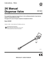
Instructions - Parts 2K Manual Dispense Valve 332198C EN For use with two component proportioners to mix and dispense beads of non-abrasive material. For professional use only. Not approved for use in European explosive atmosphere locations. Model 24R021 2000 psi (14 MPa, 137 bar) Maximum Fluid Working Pressure Important Safety Instructions Read all warnings and instructions in this manual and the system manual. Save all instructions. ti20167a Related Manuals Contents Related Manuals . . . . . . . . . . . . . . . . . . . . . . . . . . . 2 Warnings . . . . . . . . . . . . . . . . . . . . . . . . . . . . . . . . . 3 Important Isocyanate (ISO) Information . . . . . . . . 5 Isocyanate Conditions . . . . . . . . . . . . . . . . . . . . . 5 Material Self-ignition . . . . . . . . . . . . . . . . . . . . . . 5 Keep Components A (ISO) and B (RES) Separate 5 Moisture Sensitivity of Isocyanates . . . . . . . . . . . 5 Foam Resins with 245 fa Blowing Agents . . . . . . 5 Changing Materials . . . . . . . . . . . . . . . . . . . . . . . 6 Installation . . . . . . . . . . . . . . . . . . . . . . . . . . . . . . . . 7 Operation . . . . . . . . . . . . . . . . . . . . . . . . . . . . . . . . . 8 Prime . . . . . . . . . . . . . . . . . . . . . . . . . . . . . . . . . . 8 Pressure Balance the Gun . . . . . . . . . . . . . . . . . 8 Ratio Checking . . . . . . . . . . . . . . . . . . . . . . . . . . 9 Install Disposable Static Mixer . . . . . . . . . . . . . . 9 Dispense . . . . . . . . . . . . . . . . . . . . . . . . . . . . . . . 9 Pressure Relief Procedure . . . . . . . . . . . . . . . . 10 Daily Shutdown . . . . . . . . . . . . . . . . . . . . . . . . . 10 Flushing . . . . . . . . . . . . . . . . . . . . . . . . . . . . . . 10 Install Restrictors or Plugs . . . . . . . . . . . . . . . . 11 Volume Balancing . . . . . . . . . . . . . . . . . . . . . . . 11 Maintenance . . . . . . . . . . . . . . . . . . . . . . . . . . . . . . 11 Routine Cleaning . . . . . . . . . . . . . . . . . . . . . . . 11 Troubleshooting . . . . . . . . . . . . . . . . . . . . . . . . . . . 12 Parts . . . . . . . . . . . . . . . . . . . . . . . . . . . . . . . . . . . . 13 Accessories . . . . . . . . . . . . . . . . . . . . . . . . . . . . . . 14 Typical Restrictor Pressure Drop . . . . . . . . . . . 15 Technical Data . . . . . . . . . . . . . . . . . . . . . . . . . . . . 15 Graco Standard Warranty . . . . . . . . . . . . . . . . . . . 16 Related Manuals The following manuals are available at www.graco.com. Part Description 3A1602 E-8p Proportioner Operation and Repair 2 332198C Warnings Warnings The following warnings are for the setup, use, grounding, maintenance, and repair of this equipment. The exclamation point symbol alerts you to a general warning and the hazard symbols refer to procedure-specific risks. When these symbols appear in the body of this manual or on warning labels, refer back to these Warnings. Product-specific hazard symbols and warnings not covered in this section may appear throughout the body of this manual where applicable. WARNING TOXIC FLUID OR FUMES HAZARD Toxic fluids or fumes can cause serious injury or death if splashed in the eyes or on skin, inhaled, or swallowed. • Read MSDSs to know the specific hazards of the fluids you are using. • Store hazardous fluid in approved containers, and dispose of it according to applicable guidelines. • Always wear chemically impermeable gloves when spraying, dispensing, or cleaning equipment. PERSONAL PROTECTIVE EQUIPMENT Wear appropriate protective equipment when in the work area to help prevent serious injury, including eye injury, hearing loss, inhalation of toxic fumes, and burns. This protective equipment includes but is not limited to: • Protective eyewear, and hearing protection. • Respirators, protective clothing, and gloves as recommended by the fluid and solvent manufacturer + SKIN INJECTION HAZARD High-pressure fluid from dispensing device, hose leaks, or ruptured components will pierce skin. This may look like just a cut, but it is a serious injury that can result in amputation. Get immediate surgical treatment. • Do not point dispensing device at anyone or at any part of the body. • Do not put your hand over the fluid outlet. • Do not stop or deflect leaks with your hand, body, glove, or rag. • Follow the Pressure Relief Procedure when you stop dispensing and before cleaning, checking, or servicing equipment. • Tighten all fluid connections before operating the equipment. • Check hoses and couplings daily. Replace worn or damaged parts immediately. FIRE AND EXPLOSION HAZARD Flammable fumes, such as solvent and paint fumes, in work area can ignite or explode. To help prevent fire and explosion: • Use equipment only in well ventilated area. • Eliminate all ignition sources; such as pilot lights, cigarettes, portable electric lamps, and plastic drop cloths (potential static arc). • Keep work area free of debris, including solvent, rags and gasoline. • Do not plug or unplug power cords, or turn power or light switches on or off when flammable fumes are present. • Ground all equipment in the work area. See Grounding instructions. • Use only grounded hoses. • Hold gun firmly to side of grounded pail when triggering into pail. Do not use pail liners unless they are antistatic or conductive. • Stop operation immediately if static sparking occurs or you feel a shock. Do not use equipment until you identify and correct the problem. • Keep a working fire extinguisher in the work area. 332198C 3 Warnings WARNING EQUIPMENT MISUSE HAZARD Misuse can cause death or serious injury. • Do not operate the unit when fatigued or under the influence of drugs or alcohol. • Do not exceed the maximum working pressure or temperature rating of the lowest rated system component. See Technical Data in all equipment manuals. • Use fluids and solvents that are compatible with equipment wetted parts. See Technical Data in all equipment manuals. Read fluid and solvent manufacturer’s warnings. For complete information about your material, request MSDS from distributor or retailer. • Do not leave the work area while equipment is energized or under pressure. • Turn off all equipment and follow the Pressure Relief Procedure when equipment is not in use. • Check equipment daily. Repair or replace worn or damaged parts immediately with genuine manufacturer’s replacement parts only. • Do not alter or modify equipment. Alterations or modifications may void agency approvals and create safety hazards. • Make sure all equipment is rated and approved for the environment in which you are using it. • Use equipment only for its intended purpose. Call your distributor for information. • Route hoses and cables away from traffic areas, sharp edges, moving parts, and hot surfaces. • Do not kink or over bend hoses or use hoses to pull equipment. • Keep children and animals away from work area. • Comply with all applicable safety regulations. PRESSURIZED ALUMINUM PARTS HAZARD Use of fluids that are incompatible with aluminum in pressurized equipment can cause serious chemical reaction and equipment rupture. Failure to follow this warning can result in death, serious injury, or property damage. • Do not use 1,1,1-trichloroethane, methylene chloride, other halogenated hydrocarbon solvents or fluids containing such solvents. • Many other fluids may contain chemicals that can react with aluminum. Contact your material supplier for compatibility. 4 332198C Important Isocyanate (ISO) Information Important Isocyanate (ISO) Information Isocyanates (ISO) are catalysts used in two component materials. Isocyanate Conditions Spraying or dispensing materials containing isocyanates creates potentially harmful mists, vapors, and atomized particulates. Read material manufacturer’s warnings and material MSDS to know specific hazards and precautions related to isocyanates. Prevent inhalation of isocyanate mists, vapors, and atomized particulates by providing sufficient ventilation in the work area. If sufficient ventilation is not available, a supplied-air respirator is required for everyone in the work area. To prevent contact with isocyanates, appropriate personal protective equipment, including chemically impermeable gloves, boots, aprons, and goggles, is also required for everyone in the work area. Material Self-ignition Some materials may become self-igniting if applied too thick. Read material manufacturer’s warnings and material MSDS. Keep Components A (ISO) and B (RES) Separate Cross-contamination can result in cured material in fluid lines which could cause serious injury or damage equipment. To prevent cross-contamination: • Never interchange component A (ISO) and component B (RES) wetted parts. • Never use solvent on one side if it has been contaminated from the other side. 332198C Moisture Sensitivity of Isocyanates Exposure to moisture (such as humidity) will cause ISO to partially cure; forming small, hard, abrasive crystals, which become suspended in the fluid. Eventually a film will form on the surface and the ISO will begin to gel, increasing in viscosity. NOTICE Partially cured ISO will reduce performance and the life of all wetted parts. • Always use a sealed container with a desiccant dryer in the vent, or a nitrogen atmosphere. Never store ISO in an open container. • Keep the ISO pump wet cup or reservoir (if installed) filled with appropriate lubricant. The lubricant creates a barrier between the ISO and the atmosphere. • Use only moisture-proof hoses compatible with ISO. • Never use reclaimed solvents, which may contain moisture. Always keep solvent containers closed when not in use. • Always lubricate threaded parts with an appropriate lubricant when reassembling. NOTE: The amount of film formation and rate of crystallization varies depending on the blend of ISO, the humidity, and the temperature. Foam Resins with 245 fa Blowing Agents Some foam blowing agents will froth at temperatures above 90°F (33°C) when not under pressure, especially if agitated. To reduce frothing, minimize preheating in a circulation system. 5 Important Isocyanate (ISO) Information Changing Materials NOTICE Changing the material types used in your equipment requires special attention to avoid equipment damage and downtime. • When changing materials, flush the equipment multiple times to ensure it is thoroughly clean. • Always clean the fluid inlet strainers after flushing. • Check with your material manufacturer for chemical compatibility. • When changing between epoxies and urethanes or polyureas, disassemble and clean all fluid components and change hoses. Epoxies often have amines on the B (hardener) side. Polyureas often have amines on the B (resin) side 6 332198C Installation Installation 3. Thread the handle (K) onto the manifold (L). 4. Connect the gun fluid supply hoses to the A (ISO) and B (RES) fluid inlets of gun. 1. Relieve all system pressure before installing the dispense valve. NOTE: Hoses are color coded: red for component A (ISO), blue for component B (RES). Red (ISO) usually is connected to the left side of the valve (as viewed from the back of the gun). 5. Perform Prime procedure, page 8. GROUNDING The equipment must be grounded to reduce the risk of static sparking. Static sparking can cause fumes to ignite or explode. Grounding provides an escape wire for the electric current. 2. Ground the gun through connection to a properly grounded fluid hose and pump. See your system manual for further information. C A D B L H M J Key: A B C D E F G H J K L M A (Iso) Hose B (Resin) Hose OFF (Closed) Position ON (Open) Position Restrictor or Plug Outlet Manifold Static Mixer Nut (Static Mixer Not Shown) Lever Inlet Ball Valves Handle Manifold Check Valves F ti20166a K E E G FIG. 1 332198C 7 Operation Operation Prime 1. Use lever (H) to close the dispense valve inlet ball valves (J). NOTICE Perform this procedure whenever air is introduced into the material lines, such as after connecting the material supply lines to the dispense valve. Always open and close lever (H) fully and quickly. Opening the valve partially or slowly will cause soft spots in the material and may shut down the proportioner because of a pressure imbalance. 1. Perform Pressure Relief Procedure on page 10. 2. Remove static mixer. 2. If a static mixer is installed, remove static mixer. 3. With the static mixer removed, dispense into a waste container. Note pressure gauge readings. If pressures are more than 25% apart, continue to next step. If not, pressures are sufficiently balanced. 3. Use lever (H) to open the dispense valve inlet ball valves (J). NOTICE Always open and close lever (H) fully and quickly. Opening the valve partially or slowly will cause soft spots in the material and may shut down the proportioner because of a pressure imbalance. 4. If necessary, prime the proportioner. See proportioner manual for priming instructions. 5. Run the proportioner until clean, air-free material begins to exit the dispense valve. 6. If necessary, Pressure Balance the Gun. 4. If pressures are more than 25% apart, replace one or both plugs or restrictors with a different restrictor size: NOTE: An extra 0.032 in. restrictor is included with the gun. If necessary, use this restrictor to balance the pressures. Put the larger orifice on the side with the higher viscosity material. a. Perform Pressure Relief Procedure on page 10. b. 7. Install Disposable Static Mixer. Pressure Balance the Gun NOTE: The valve should be able to achieve the desired flow rate at a pressure of 200-1500 psi (1.4-10 MPa, 14-103 bar). A (ISO) and B (RES) pressures should balance within 25% of each other. c. Balancing the back pressure: • • • • 8 controls ratio lead-lag when the gun opens holds pressure in the hose, providing a very smooth flow minimizes oozing from mixer minimizes material crossover. Select the new restrictors required to achieve desired back pressure and balance. See pressure drop chart in FIG. 2 on page 15. Install Restrictors or Plugs, see page 11. d. Repeat this procedure to verify pressures are balanced. 332198C Operation Ratio Checking NOTE: Use the lowest proportioner pressure setting that produces the desired flow. NOTE: Use ratio check nozzle 255247 with retaining nut 512292. Purchase separately. The output mix ratio of your proportioner can be checked by dispensing the two fluids separately out of the nosepiece into tared cups. The cups can then be weighed and the weights divided to get the mix ratio by weight. Ratio checks provide information about the ratio of an overall sample. Transient problems (soft spots) caused by starting and stopping the flow (lead-lag) may not show up in this kind of ratio check. Physical tests of the mixed fluid are the best check of correct ratio and mix quality. Install Disposable Static Mixer NOTICE If the proportioner pressure setting is too high, any differences in viscosity will cause a pressure differential that will result in improper mixing. 5. Use lever (H) to open and close dispense valve inlet ball valves (J) as desired to dispense materials. NOTICE Always open and close lever (H) fully and quickly. Opening the valve partially or slowly will cause soft spots in the material and may shut down the proportioner because of a pressure imbalance. 6. If stopping dispensing for longer than the cure time of the materials: a. Use lever (H) to close dispense valve inlet ball valves (J) as desired to dispense materials. 1. Perform Pressure Relief Procedure, page 10. b. Keep static mixer installed. 2. Use lever (H) to close the dispense valve inlet ball valves (J). c. When ready to dispense again, Install Disposable Static Mixer, page 9. 3. Coat threads of outlet manifold (F) with grease to prevent material curing on threads. 4. Install static mixer and secure with nut (G). 7. When done using the dispense valve for the day, perform Daily Shutdown on page 10. Dispense 1. If it is possible that air may be in the fluid lines, perform Prime procedure on page 8. 2. If the gun has not yet been pressure balanced, perform Pressure Balance the Gun procedure on page 8. 3. If the fluid in the static mixer is cured or there is no static mixer installed, Install Disposable Static Mixer, page 9. 4. Start proportioner and adjust to desired pressure. See proportioner manual for instructions. 332198C 9 Operation Pressure Relief Procedure Follow the Pressure Relief Procedure whenever you see this symbol. This equipment stays pressurized until pressure is manually relieved. To help prevent serious injury from pressurized fluid, such as skin injection, splashing fluid and moving parts, follow the Pressure Relief Procedure when you stop spraying and before cleaning, checking, or servicing the equipment. Daily Shutdown NOTE: For brief shutdowns, leave the cured mixer in place until it is time to use a fresh mixer. When you finish using the 2K Manual Dispense Valve, clean the outlet manifold (F) and protect it from drying or crystallization as follows: 1. Perform Pressure Relief Procedure, page 10. 2. Remove and properly dispose of the static mixer. This procedure describes how to relieve pressure from the dispense valve. See the supply system manual for instructions on relieving pressure from the entire system. 3. Dispense one shot of material into a waste container to clear any crossover in the outlet manifold (F). 1. Shut off material supply pumps. 4. Wipe the nose with a clean rag, being careful not to let the materials contact each other. 2. With the valve pointed into a grounded metal pail, use the lever (H) to open the inlet ball valves (J) and relieve the fluid pressure. 5. Install PTFE night capt (19) and retaining nut (G). Flushing 3. If the valve nozzle or fluid hose is clogged or if pressure has not been fully relieved after following the steps above: a. Use lever (H) to close dispense valve inlet ball valves (J). 10 b. VERY SLOWLY loosen the static mixer nut (G) from the outlet manifold (F) or the hose end coupling to relieve pressure gradually, then loosen completely. Clear hose or nozzle obstruction. c. Use lever (H) to open dispense valve inlet ball valves (J). Flush the valve regularly to remove material build up. 1. Perform Pressure Relief Procedure, page 10. 2. Remove static mixer. 3. To maintain ground continuity, press and hold a metal part of the dispense valve against the side of a grounded metal pail then pump solvent through the gun into the grounded metal pail until clean solvent is dispensed. Use the lowest pressure possible while dispensing solvent. 332198C Maintenance Install Restrictors or Plugs Two 0.024 in. restrictors are installed with the gun. An extra 0.032 in. restrictor is included with the gun. If necessary, use this restrictor to balance the pressures. Optional restrictors in various sizes are also available. Restrictors create back pressure and make up for viscosity differences between A (ISO) and B (RES). See pressure drop chart in FIG. 2 on page 15 and see the Volume Balancing section. See 249765 Restrictor Kit on page 14. Sizing Restrictors If resin and hardener are at or near 1:1 ratio and viscosities are similar, add a few hundred psi pressure drop to each side to prevent check valve oscillation. Use the chart in FIG. 2 on page 15, or use a restrictor about twice the size of your spray tip, on both sides. Maintenance Routine Cleaning Restrictor Screens 1. Perform Pressure Relief Procedure, page 10. 2. Remove restrictors (E). 3. If using one or more restrictors, assemble o-rings (CC) and screens (BB) onto restrictors (AA). See FIG. 2 on page 15. 4. If using one or more plugs (see Accessories on page 14), assemble o-rings (CC) onto plugs. 5. Screw assembled restrictors or plugs into outlet manifold (F). NOTICE Restrictors and plugs can be damaged if they are overtightened. Torque to 40-50 in-lb (4.5-5.6 N•m). Volume Balancing Soak the restrictor screens in solvent regularly to clean. If soaking is ineffective, replace restrictor screens. Restrictors Soak the restrictors in solvent and use the included vise (30) and drill bit (31) to clean the orifice. Check Valves Soak the check valves in solvent. Use a small screw driver to actuate the check valve ball and spring to remove any restriction. Ensure fluid flows freely through the check valve before re-installing. Outlet Manifold Use drill bits to clean the outlet manifold (F) regularly. See the following drill bit size table. Ratio errors can occur between the proportioner and the manifold, even if the proportioner output ratio is very accurate. Item Different restrictor sizes are available to correct imbalances. See FIG. 2 on page 15 for available sizes. (Restrictor size) 0.018 in. . . . . . . #77 (0.45 mm) Check Valve Imbalance If resin and hardener are at or near 1:1 ratio, when one check valve opens, the resulting surge closes the other. This check valve oscillation causes ratio imbalance. Install restrictors on both sides to meter a smooth flow to the manifold. 332198C Drill Bit Size Outlet manifold fluid outlet . . . . . 1/4 in. (6 mm) Outlet manifold inner passage . . 1/8 in. (3 mm) 0.024 in. . . . . . . . . . . . . . . . . . . . #73 (0.61 mm); included 0.032 in. . . . . . . . . . . . . . . . . . . . #67 (0.81 mm) 0.040 in. . . . . . . . . . . . . . . . . . . . #60 (1.01 mm) 0.062 in. . . . . . . . . . . . . . . . . . . . 1/16 in. (1.59 mm) 0.094 in. . . . . . . . . . . . . . . . . . . . 3/32 in. (2.38 mm) Drill bit pin vise . . . . . . . . . . . . . . 117661; included 11 Troubleshooting Troubleshooting Problem Cause Pressure is higher on one side when setting pressure with function knob. Pump intake valve partially plugged. Clean pump intake valve. Air in hose. Fluid is compressible. Purge air from hose. Unequal size hoses. Use matching hoses. Feathering the valve lever to decrease the flow rate through the gun. When opening or closing the valve, always move the lever all the way. Do not try to control the flow rate by partially opening the lever. Unequal viscosities. Check that A (ISO) and B (RES) chemicals are within the chemical manufacturer’s specified application temperature range. Pressures are not balanced when running but pressure is generated and holds on both strokes. Solution Change restrictor at mix point to balance back pressure. A (ISO) side rich; lack of B (RES) side. B (RES) side rich; lack of A (ISO) side. Flow will not shut off when ball valve lever is closed. 12 Restriction on one side. Clean mix module, restrictors, or check valves at mix manifold. A (ISO) side gauge is low. B (RES) side restriction downstream of gauge. Check gun check valve spring, mix module, or mix manifold restrictor screen. B (RES) side gauge is low. B (RES) side material supply problem. Check B (RES) side inlet strainer and pump intake valve. A (ISO) side gauge is low. A (ISO) side material supply problem. Check A (ISO) side inlet strainer and pump intake valve. B (RES) side gauge is low. A (ISO) side restriction downstream of gauge. Check gun check valve spring, mix module, or mix manifold restrictor screen. Worn ball valve seat of ball. Replace ball valve. See assembly specifications in illustration on page 13. 332198C Parts Parts 14 8 8 13 12 4 59 5 3 6 48 10 1 27 4 27 ti20581b 3 28 16 10 11 NOTE: Apply thread sealant on all tapered thread fittings. 5 Orient lever (9) and adjust balls in valves (8) so they are closed when lever is pulled back. Carefully install the lever onto the ball valve (8) studs, making sure the stud flats line up with the slots in the lever. 18 8 Make sure that #6 JIC adapter (13) is on the right and #5 JIC adapter (14) is on the left of the inlet manifold (1), when viewed from the rear of the gun. 4 Install and tighten ball valves (8) so that the studs are pointing away from each other. The flats line up squarely with the flat of the inlet manifold (1), and the pressure laser marking are on the handle (2) side of the inlet manifold (1). 7 12 7 Apply red thread locking liquid to the threads of the handle (2). 3 When installing a new ball valve (8), remove the acorn nuts and handle from the ball valves (8). Keep the acorn nuts, discard the handle. 6 9 9 Squarely align outlet manifold (6) to inlet manifold (1). 10 Apply lithium grease. 11 Torque restrictors (18) to 40-50 in-lb (4.5-5.6 N•m). 12 Hand tighten mixer nut (7) onto outlet manifold (6). 6 Install acorn nuts from ball valves (8) on top of the lever (9). Torque to 40-50 in-lb (4.5-5.6 N•m). Ref 1 2 3 4 5 6 7 8 9 10 12 13 14 15 Part 24R986 16U410 16F422 119984 15G421 24K994 512292 214037 217562 100721 113093 117506 117595 512289 332198C Description Qty MANIFOLD, inlet 1 HANDLE, manual 2K gun 1 GRIP, handle, 390st 1 FITTING, union, 1/8 npt x 5/16 tube 4 TUBE, 5/16 extension, assembly 2 MANIFOLD, outlet 1 NUT, mixer 1 VALVE, ball, 1/4, 5000 psi, with lever 2 LEVER, valve 1 PLUG, pipe 2 CONNECTOR, pipe 2 FITTING, swivel, 1/4 npt x #6 JIC 1 FITTING, swivel, 1/4 npt x #5 JIC 1 MIXER, 1/2-30 spray 10 Ref Part Description 16 111516 PACKING, o-ring 17 249036 PACKING, o-ring (not shown), includes qty 6 of item 16 18 15E373 RESTRICTOR, 0.024 in. 19 15K652 CAP, night 27 563199 VALVE, check, 1/8 npt, rev, 5000 28 15E378 FILTER, screen, 40 mesh 29 118665 GREASE, Fusion® 30 117661 VISE, drill pit pin 31 --BIT, 0.024 in. cleanout drill 32 15E374 RESTRICTOR, 0.032 in. Qty 2 1 2 1 2 2 1 1 1 1 --- Not for sale. Items are shipped loose. 13 Accessories Accessories Restrictors 15E372 15E373 15E374 15E375 15E376 15E377 0.018 in. Orifice Restrictor 0.024 in. Orifice Restrictor 0.032 in. Orifice Restrictor 0.040 in. Orifice Restrictor 0.062 in. Orifice Restrictor 0.094 in. Orifice Restrictor Gun Length Reduction To reduce the overall length of the gun from 47 in. (1194 mm) to 24 in. (610 mm), purchase two of each of the following fittings: 503279 and 151243. Use these fittings to replace fittings (4) and tubes (5). Standard Disposable Mixer 512289† 249765 Restrictor Kit Includes one each of restrictor sizes 0.018, 0.024, 0.032, 0.040, 0.062, and 0.094 in., one plug with no restriction, package of 10 screens, and package of 6 o-rings. Alternate Disposable Mixers 120042 512014 15E370 Plug Fits restrictor port, but with minimal restriction. Uses 249036 O-ring Kit. 249036 Restrictor O-ring Kit 512016 512017 551979† Package of 6. 512291 249037 Restrictor Screen Kit 40 mesh. Package of 10. 15K652 PTFE Night Cap Partially fill with ISO pump oil or ISO pump grease to protect outlet manifold (6) from air and moisture. 217374 ISO Pump Oil 1/2 in. (13 mm) ID x 5/8 in. (16 mm) OD x 30 element. 512292† 1/4 in. (6 mm) ID x 3/8 in. (10 mm) OD x 24 element; package of 50. 1/4 in. (6 mm) ID x 3/8 in. (10 mm) OD x 32 element. 3/8 in. (10 mm) ID x 1/2 in. (13 mm) OD x 24 element. 3/8 in. (10 mm) ID x 1/2 in. (13 mm) OD x 30 element. 1/2 in. (13 mm) ID x 5/8 in. (16 mm) OD x 36 element. Retainer Nut for 1/2 in. (13 mm) OD and smaller mixers. Retainer Nut for 5/8 in. (16 mm) OD mixers. Use retainer nut 512291 for 1/2 in. (13 mm) OD and smaller mixers. † Use retainer nut 512292 for 5/8 in. (16 mm) OD and smaller mixers. 1 pint (0.5 liter) container. 106565 ISO Pump Grease 14.6 oz (0.4 kg) cartridge 255247 Ratio Check Nozzle Use with retainer nut 512292. 246385 Pump Inlet Strainer Use to strain material before it enters proportioner. 14 332198C Technical Data Typical Restrictor Pressure Drop Pressure Drop in psi (MPa, bar) 2500 (17.5, 175) Key: 5000 cps, 1.0 gpm (3.8 lpm) 2000 (14.0, 140) 5000 cps, 0.25 gpm (0.95 lpm) 1000 cps, 0.25 gpm (0.95 lpm) 1500 (10.5, 105) 500 cps, 0.25 gpm (0.95 lpm) 200 cps, 0.25 gpm (0.95 lpm) 1000 (7.0, 70) 200 cps, 0.10 gpm (0.38 lpm) 500 (3.5, 35) 249036 O-ring (CC) 0.094 15E377 0.062 15E376 0.040 15E375 0.032 15E374 0.024 15E373 0.018 15E372 Restrictor Diameter and Part No. Restrictors use 40 mesh screens and o-rings. Order 249037 Screens (package of 10) and 249036 O-rings (package of 6). Restrictor Fitting (AA) 249037 Screen (BB) TI5627a TI5628a FIG. 2 Technical Data Maximum Fluid Working Pressure . . . . . . . . . . . . . . . . Wetted Parts . . . . . . . . . . . . . . . . . . . . . . . . . . . . . . . . . 332198C 2000 psi (14 MPa, 137 bar) Carbon steel, stainless steel, aluminum, chemically resistant o-rings, PTFE, PEEK 15 Graco Standard Warranty Graco warrants all equipment referenced in this document which is manufactured by Graco and bearing its name to be free from defects in material and workmanship on the date of sale to the original purchaser for use. With the exception of any special, extended, or limited warranty published by Graco, Graco will, for a period of twelve months from the date of sale, repair or replace any part of the equipment determined by Graco to be defective. This warranty applies only when the equipment is installed, operated and maintained in accordance with Graco’s written recommendations. This warranty does not cover, and Graco shall not be liable for general wear and tear, or any malfunction, damage or wear caused by faulty installation, misapplication, abrasion, corrosion, inadequate or improper maintenance, negligence, accident, tampering, or substitution of non-Graco component parts. Nor shall Graco be liable for malfunction, damage or wear caused by the incompatibility of Graco equipment with structures, accessories, equipment or materials not supplied by Graco, or the improper design, manufacture, installation, operation or maintenance of structures, accessories, equipment or materials not supplied by Graco. This warranty is conditioned upon the prepaid return of the equipment claimed to be defective to an authorized Graco distributor for verification of the claimed defect. If the claimed defect is verified, Graco will repair or replace free of charge any defective parts. The equipment will be returned to the original purchaser transportation prepaid. If inspection of the equipment does not disclose any defect in material or workmanship, repairs will be made at a reasonable charge, which charges may include the costs of parts, labor, and transportation. THIS WARRANTY IS EXCLUSIVE, AND IS IN LIEU OF ANY OTHER WARRANTIES, EXPRESS OR IMPLIED, INCLUDING BUT NOT LIMITED TO WARRANTY OF MERCHANTABILITY OR WARRANTY OF FITNESS FOR A PARTICULAR PURPOSE. Graco’s sole obligation and buyer’s sole remedy for any breach of warranty shall be as set forth above. The buyer agrees that no other remedy (including, but not limited to, incidental or consequential damages for lost profits, lost sales, injury to person or property, or any other incidental or consequential loss) shall be available. Any action for breach of warranty must be brought within two (2) years of the date of sale. GRACO MAKES NO WARRANTY, AND DISCLAIMS ALL IMPLIED WARRANTIES OF MERCHANTABILITY AND FITNESS FOR A PARTICULAR PURPOSE, IN CONNECTION WITH ACCESSORIES, EQUIPMENT, MATERIALS OR COMPONENTS SOLD BUT NOT MANUFACTURED BY GRACO. These items sold, but not manufactured by Graco (such as electric motors, switches, hose, etc.), are subject to the warranty, if any, of their manufacturer. Graco will provide purchaser with reasonable assistance in making any claim for breach of these warranties. In no event will Graco be liable for indirect, incidental, special or consequential damages resulting from Graco supplying equipment hereunder, or the furnishing, performance, or use of any products or other goods sold hereto, whether due to a breach of contract, breach of warranty, the negligence of Graco, or otherwise. FOR GRACO CANADA CUSTOMERS The Parties acknowledge that they have required that the present document, as well as all documents, notices and legal proceedings entered into, given or instituted pursuant hereto or relating directly or indirectly hereto, be drawn up in English. Les parties reconnaissent avoir convenu que la rédaction du présente document sera en Anglais, ainsi que tous documents, avis et procédures judiciaires exécutés, donnés ou intentés, à la suite de ou en rapport, directement ou indirectement, avec les procédures concernées. Graco Information For the latest information about Graco products, visit www.graco.com. TO PLACE AN ORDER, contact your Graco distributor or call to identify the nearest distributor. Phone: 612-623-6921 or Toll Free: 1-800-328-0211 Fax: 612-378-3505 All written and visual data contained in this document reflects the latest product information available at the time of publication. Graco reserves the right to make changes at any time without notice. For patent information, see www.graco.com/patents. Original instructions. This manual contains English. MM 332198 Graco Headquarters: Minneapolis International Offices: Belgium, China, Japan, Korea GRACO INC. AND SUBSIDIARIES • P.O. BOX 1441 • MINNEAPOLIS MN 55440-1441 • USA Copyright 2012, Graco Inc. All Graco manufacturing locations are registered to ISO 9001. www.graco.com Revised August 2013