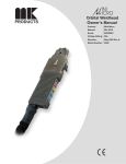
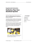
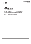
1
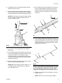
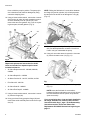
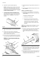
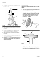
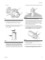
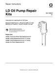
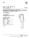
Repair Instructions
LD Grease Pump
Repair Kits
Instructions for repairing the LD Grease Pump.
Maximum Fluid Pressure - 7500 psi (51.7 MPa, 517 bar)
Maximum Air Pressure - 150 psi (1.03 MPa, 10.3 bar)
Important Safety Instructions
Read all warnings and instructions in this manual and
in your LD Series Oil or Grease Pump manual. Save
all instructions.
Repair Kits:
24H854: Throat and Piston Seal Replacement Kit
24H856: O-Ring and Seal Replacement Kit
24U984: Air Piston Replacement Kit
3A1495C
EN
Warnings
Warnings
The following warnings are for the setup, use, grounding, maintenance, and repair of this equipment. The exclamation point symbol alerts you to a general warning and the hazard symbols refer to procedure-specific risks. When
these symbols appear in the body of this manual, refer back to these Warnings. Product-specific hazard symbols and
warnings not covered in this section may appear throughout the body of this manual where applicable.
WARNING
SKIN INJECTION HAZARD
High-pressure fluid from dispense valve, hose leaks, or ruptured components will pierce skin. This may
look like just a cut, but it is a serious injury that can result in amputation. Get immediate surgical
treatment.
• Do not point dispense valve at anyone or at any part of the body.
• Do not put your hand over the end of the dispense nozzle.
• Do not stop or deflect leaks with your hand, body, glove, or rag.
• Follow Pressure Relief Procedure in this manual, when you stop spraying and before cleaning,
checking, or servicing equipment.
• Tighten all fluid connections before operating the equipment.
• Check hoses and couplings daily. Replace worn or damaged parts immediately.
PRESSURIZED ALUMINUM PARTS HAZARD
Use of fluids that are incompatible with aluminum in pressurized equipment can cause serious chemical
reaction and equipment rupture. Failure to follow this warning can result in death, serious injury, or
property damage.
• Do not use 1,1,1-trichloroethane, methylene chloride, other halogenated hydrocarbon solvents or
fluids containing such solvents.
• Many other fluids may contain chemicals that can react with aluminum. Contact your material supplier
for compatibility.
PERSONAL PROTECTIVE EQUIPMENT
You must wear appropriate protective equipment when operating, servicing, or when in the operating area
of the equipment to help protect you from serious injury, including eye injury, hearing loss, inhalation of
toxic fumes, and burns. This equipment includes but is not limited to:
• Protective eyewear, and hearing protection.
• Respirators, protective clothing, and gloves as recommended by the fluid and solvent manufacturer.
2
3A1495C
Instructions
Instructions
Always use all new parts included in your kit and dispose of replaced parts according to all state and local
regulations for disposal of discarded components.
Inspect all parts when disassembling the pump. Replace
any and all worn and damaged parts.
Pressure Relief Procedure
Disassembly
The following disassembly instructions describe the procedure for completely disassembling the LD grease
pump. Depending on the repair/maintenance procedure
you are performing on the pump, it may not be necessary to entirely disassemble the pump or perform all
steps in this procedure.
The reference numbers used in the following instructions correspond to the reference numbers used in the
LD Series Oil and Grease Pump instruction manual.
The equipment stays pressurized until pressure is manually
relieved. To reduce the risk of serious injury from pressurized fluid, fluid from the valve, or splashing fluid, follow the
procedure whenever you:
•
•
•
•
are instructed to relieve pressure
stop dispensing
check, clean, or service any system equipment
install or clean dispensing devices.
1. Stop the pump. Follow Pressure Relief Procedure,
page 3.
1. Close the pump’s bleed-type master air valve.
2. Disconnect and remove the pump from its installed
location.
2. Close the pump air regulator and disconnect the air
supply hose.
3. Clamp the pump (1) upside down in a vise as shown
in Fig. 1.
3. Open the dispensing valve and dispense fluid into a
waste bucket/container until pressure is fully
relieved.
If you suspect that the dispensing valve is clogged, or
that pressure has not been fully relieved after following
the steps above, very slowly loosen the dispensing
valve coupler or hose end coupling to relieve pressure
gradually, then loosen completely.
NOTE: Take care to only use enough clamping
force to hold the pump in position. The pump cylinder is aluminum and could be damaged by using
excessive clamping force.
1
Fig. 1
If you are only servicing the air valve (40) and seals
(18) or air piston (15), skip Steps 4 - 14.
3A1495C
3
Instructions
4. Secure a strap wrench around the shovel cylinder
(27). Use the strap wrench to turn the shovel cylinder counter-clockwise to loosen and remove it from
the pump assembly (Fig. 2).
6. Use a wrench to loosen and remove the seal
retainer (29) (Fig. 4).
19
NOTE: After a few turns, the shovel cylinder should
be loose enough to finish turning it with your hand to
remove this part.
35
27
29
34
34
Fig. 4
7. Tighten a strap wrench on the spacer cylinder (36)
and use it to prevent this part from moving. Secure a
strap wrench around the cylinder (26) and use it to
turn the cylinder to loosen and remove it from the
pump assembly. (Fig. 5). Remove the intake seal
(28).
Fig. 2
5. Use an adjustable wrench to hold the priming rod
(34) securely. Use a second adjustable wrench to
loosen and remove the nut (19) and priming piston
(35) (Fig. 3, Fig. 4).
26
19, 35
30
34
28
Fig. 3
36
Fig. 5
4
3A1495C
Instructions
8. If the gasket (30) is still inside the spacer cylinder
(36) use a pick to remove.
9. Secure a strap wrench around the spacer cylinder
(36) and use it to turn the cylinder counter clockwise
to loosen and remove it from the flange (22) (Fig. 6).
13. Use a rubber hammer and small punch to drive out
pin (8), holding together the priming rod (34) and
piston rod (23). Turn the priming rod (34) counter
clockwise to loosen and remove it from the piston
rod (Fig. 7).
NOTE: After a few turns, the spacer cylinder should
be loose enough to finish loosening it with your
hand to remove this part.
8
23
24
36
32
34
PULL
8
30
22
8
28
Fig. 7
14. Use a rubber hammer and small punch to drive out
pin (8), holding together the connection rod (32) and
displacement rod (25). Turn the connection rod (32)
counter clockwise to loosen and remove it from the
displacement rod (Fig. 8).
25
Fig. 6
10. Use a pick to remove gasket (30) from inside the
flange (22).
11. Use a rubber hammer and small punch to drive out
pin (8), holding together the piston rod (23) and the
connection rod (32). Turn the piston rod (23)
counter clockwise to loosen and remove it from the
connection rod. Remove the piston seal (24) from
the piston rod (Fig. 8).
34
32
24
12. Remove the pump assembly from the vise and set it
down on a clean, hard work surface.
NOTE: When removing the pin (8) in Steps 12 - 14,
it is helpful to place a support such as a piece of
wood, below the rods.
23
Fig. 8
28
If you are only replacing or repairing the pump lower
continue instructions beginning with Step 14, page
8 of the Reassembly instructions and the related
O-Ring and Seal Replacement Kit 24H856, page 12.
15. Clamp the air cylinder (21) horizontally in a vise as
shown in Fig. 9.
NOTE: Take care to only use enough clamping
3A1495C
5
Instructions
force to hold the pump in position. The pump cylinder is aluminum and could be damaged by using
excessive clamping force.
16. Using a 10 mm socket wrench, remove the 4 screws
(43) from the air valve (40) and completely remove
air valve assembly from air cylinder (21). Also
remove the two cover gaskets 18). If you are replacing these parts, discard gaskets. (Fig. 9).
40
NOTE: Sliding the flat blade of a screw driver between
the flange (22) and air cylinder (21) will help separate
the two parts. Be careful not to damage the o-ring (6)
(Fig. 10).
21
43
18
21
6
Fig. 10
19. Pull the flange assembly off the displacement rod
(25). Set the displacement rod aside. You will not
need it until you reassemble the pump.
20. Using a 5 mm socket wrench remove the 3 screws
(3) from the bottom cover (14) (Fig. 11).
21
Fig. 9
14
Repair and replacement instructions for the Air
Valve are included in a separate repair manual
included with the kit:
•
Air Valve Replacement Kit - 24H848, 24H849,
24H850
•
Air Valve Repair Kit - 24H798
•
Air Motor Service Kit - 24J757, 24J758, 24J759
•
Pilot Valve Kit - 24H749
•
Air Valve Seal Kit - 24H851
•
Air Valve End Cap Kit - 24H852
17. Using a 10 mm socket wrench, remove the 5 screws
(4) from the flange (22).
18. Using your hand, firmly grasp the flange (22) and
remove the entire assembly from inside the air cylinder (21).
6
3
22
Fig. 11
21. Separate the bottom cover (14) from the flange (22)
(Fig. 11).
NOTE: Insert the flat blade of a screwdriver
between the flange and bottom cover to help loosen
the seal between these two pieces and pull them
apart more easily.
If you are replacing the o-rings and seals installed in
the flange, bottom cover, and air piston continue
instructions with Step 1, page 7 of the Reassembly
instructions and the Throat and Piston Seal
Replacement Kit 24H854 instructions beginning on
page 11.
3A1495C
Instructions
Pump Reassembly
NOTE: The following instructions describe the procedure to follow to reassemble a completely disassembled
LD grease pump. Depending on the repair/maintenance
procedure you are performing on the pump, it may not
be entirely disassembled. See the specific section(s)
related to your repair/replacement kit.
3. Install 3 screws (3) (Fig. 13). Tighten with a 5 mm
socket wrench and torque to 60-70 in lbs (6.8 – 7.9
N.m).
3
For all reassembly procedures:
•
Clean all the parts carefully in a compatible solvent,
and inspect for wear or damage. Use all the repair
kit parts during reassembly, and replace other parts
as necessary.
•
Check the all polished surfaces for scratches or
wear.
•
Lubricate all parts with a light, water-resistant
grease.
1. Install new o-rings and seals in bottom cover (14)
and flange (22) as described in the Throat and Piston Seal Replacement Kit 24H854, page 11. Be
sure to apply a thin coat of water-resistant grease to
all o-rings and seals.
Fig. 13
4. Apply a thin coat of grease round the top of the displacement rod (50). Push the displacement rod
through the opening in the bottom cover and into the
flange assembly as shown in Fig. 14.
22
50
2. Align pilot valve (20) installed in bottom cover with
opening (a) in flange (22) as shown in Fig. 12. Compress the bottom cover (14) and flange (22)
together.
14
20
a
Fig. 14
5. Install the air cylinder (21) over the bottom cover
(14). Place the top of the air cylinder down on a
clean hard surface. Use the palms of your hands to
press the bottom cover firmly into the air cylinder
(Fig. 15).
14
22
Fig. 12
21
Fig. 15
3A1495C
7
Instructions
11. Install screws (43). Torque to 60-70 in. lbs (6.8 - 7.9
N.m).
6. Install the 5 screws (4) wrench tight only.
NOTE: If installing a new air cylinder (27), the mating holes are not threaded by design. Use thread
forming screws (4) to form threads as they are being
installed. Torque to 95-105 in.-lbs (10.7 - 11.8 N.m)
to ensure full thread formation.
7. To ensure there is a proper seal between the air
valve and manifold, loosen all 5 screws (Fig. 16)
approximately 1/8 to 1/4 turn. These screws will be
torqued in Step 12, AFTER the air valve (40) is
installed.
12. Torque screws (4) installed in Step 6 to 60-70 in. lbs
(6.8 - 7.9 N.m).
Muffler (17) Installation (Fig. 17)
13. Depending on your installation, the air valve (40)
can be mounted with the muffler (17) on either side
of the air valve.
To change the installation location:
a. Remove the 4 screws (43).
14
4
b. Remove the air valve (40) from its current
mounted position on the air cylinder (21) and
rotate the air valve 180 degrees, which will
reposition the muffler to face the other side of
the pump.
NOTE: When installing the pin (8) in Steps 14 - 20, it is
helpful to place a support, such as a piece of wood,
below the rods.
Fig. 16
8. Secure pump assembly in a vise as shown in Fig.
17.
9. Perform any air valve repairs / maintenance
needed. See separate instruction manual included
with the related air valve repair kit.
14. Screw the connecting rod (32) and the displacement
rod (25) together, aligning the pin hole in both
pieces to allow the pin to be pushed through (Fig.
18).
10. Be sure seals (18) are lightly greased and installed
on air valve (40). Install air valve on air cylinder (21).
NOTE: The air valve (40) can be installed in any
configuration. There is not just one correct way to
install these parts.
8
32
40
43
25
Fig. 18
17
21
18
15. Replace the pin (8). Use a rubber hammer to tap the
pin into place, being careful to make sure the sides
of the pin are flush with the outside surface of the
connecting rod (Fig. 18).
16. Install piston seal (24) over the end of the piston rod
(23). Note the correct orientation of the piston seal
on the piston rod as shown in Fig. 19.
Fig. 17
8
3A1495C
Instructions
17. Screw the piston rod (23) and the connecting rod
(32) together aligning the pin hole in both pieces to
allow the pin to be pushed through (Fig. 19).
24
8
32
23
NOTE: When there is end play at the pinned connection, you should be able to slightly move from
side-to-side, the displacement rod (25) pinned to the
connecting rod (32) and the connecting rod (32) pinned
to the piston rod (23) and piston rod (23) pinned to the
priming rod (34).
22. If these connections seem too rigid remove the pin
and adjust hole alignment by 1/2 turn in the direction
that aligns the through holes as close as possible,
axis-to-axis (Fig. 21).
NOTICE
Improper alignment will take the self-aligning feature
out of the design which could result in damage to the
pump.
Fig. 19
18. Replace the pin (8). Use a rubber hammer to tap the
pin into place, being careful to make sure the sides
of the pin are flush with the outside surface of the
connecting rod (Fig. 19).
Fig 1 - 1/2 Turn Too Shallow
19. Screw the piston rod (23) and priming rod (34)
together aligning the pin hole in both pieces to allow
the pin to be pushed through (Fig. 20).
Does not permit
end play
ti10469a
Incorrect Alignment
Fig 2 - 1/2 Turn Too Deep
28
23
30
ti10479a
Does not permit
end play
34
Fig 3 - Correct
Permits end play
ti10468a
Fig. 20
Correct Alignment
Fig. 21
20. Replace the pin (8). Use a rubber hammer to tap the
pin into place, being careful to make sure the sides
of the pin are flush with the outside surface of the
piston rod (Fig. 20)
21. Check to make sure there is end play at all pinned
connections.
23. Install spacer cylinder (36) over rod assembly. Use
a strap wrench to tighten spacer cylinder securely.
24. Install cylinder (26) and seal (30). Torque to 45 - 55
ft. lbs (61 - 75 N.m).
25. Install the intake seal (28) over the end of the priming rod (34). Note the correct orientation of the
3A1495C
9
Instructions
der securely then torque to 45 - 55 ft. lbs (61 - 75
N.m).
intake seal on the priming rod as shown in Fig. 20.
26. Install seal retainer (29) over priming rod (34) (Fig.
22).
27. Use an adjustable wrench to tighten seal retainer
securely, then torque to 45 - 55 ft lbs (61 - 75 N.m).
27
19
35
29
34
34
Fig. 24
Fig. 22
Repair Kits
28. Install the priming piston (35 and nut (19) (Fig. 3,
Fig. 4) on priming rod (34) Use an adjustable
wrench to hold the priming rod (34) securely. Use a
second adjustable wrench to tighten nut. Then
torque nut to 70 - 80 in. lbs (7.9 - 9.0 N.m) (Fig. 22
and Fig. 23).
All Repairs:
•
Unless otherwise stated, entirely disassemble pump
as described in the pump disassembly instruction
section of this manual.
•
Properly discard all replaced parts according to
local and state regulations for disposal of discarded
components.
•
Always use all new parts included in the kit to
replace the identical part on the pump.
•
Grease all parts prior to reassembly with a thin coat
of lightweight grease.
•
Reassemble pump as described in the reassembly
instruction section of this manual.
19, 35
34
Fig. 23
29. Install shovel cylinder (27) over priming rod (34)
(Fig. 24). Use a strap wrench to tighten shovel cylin-
10
3A1495C
Instructions
Throat and Piston Seal Replacement Kit 24H854 (Fig. 25)
Replacement parts for o-ring (5) installed on air piston
(15), o-rings (6 and 12) installed in bottom cover (14),
o-ring (7), u-cup seal (11) and gasket (30) installed on
flange (22), pin (8) used to reassemble rod sections,
and gasket (18) used later in reassembly of the air valve
(40). A replacement part for the retainer nut (37) is also
included in this kit.
Ref.
5
6
7
8
11
12
18
30
37
Qty
.
1
1
1
3
1
3
2
1
1
Description
O-RING, air piston
O-RING
O-RING
PIN, slotted, straight
SEAL, u-cup
O-RING
GASKET, cover, small
GASKET
NUT, retainer
7
2. Use a pick to remove the o-ring (5) installed around
the circumference of the air piston (15) (Fig. 26).
Grease the new o-ring included in the kit and install
it around the air piston.
5
15
Fig. 26
3. Use a pick to remove o-ring (7) and gasket (30) from
inside flange (22) (Fig. 27). Grease the o-ring and
replace the o-ring and gasket in flange.
18
11
6
7
8
12
30
22
37
22
5
30
Fig. 25
1. Disassemble the pump following Disassembly
Steps 1-3 (page 3), Steps 9-12 (page 5) and 15-21
(pages 5-6).
Fig. 27
3A1495C
11
Instructions
the new o-rings (12) and o-ring (6) included in the kit
and install them in the bottom cover housing.
4. Remove nut retainer (37) from flange (22) (Fig. 28).
22
12
6
37
25
14
Fig. 28
Fig. 30
5. Remove u-cup seal (11) from flange (22) (Fig. 29).
Grease and replace the u-cup seal with the new part
included in the kit and install them in the order
shown in Fig. 29.
NOTE:
• The bearing (31) is not included in the kit. This
part is reused. The bearing can be installed with
either side facing up. There is not just one way
to install this part.
•
•
8. Reassemble the pump as described in the Reassembly instructions, page 7.
O-Ring and Seal Replacement Kit - 24H856
(Fig. 31)
Replacement parts for gasket (30) installed in the flange
and around the circumference of the cylinder (26), o-ring
(10) installed around the seal retainer (29), pin (8) used
to reassemble rod sections, and replacement seals (24
and 28) installed on the displacement rod assembly.
The bearing (31) is a transition fit and in some
installations it may not be removed.
Be sure u-cup seal (11) is installed with the lips
facing down as shown in Fig. 29.
Ref.
8
10
24
28
30
Qty
.
3
1
1
1
2
Description
PIN, slotted, straight
O-RING
SEAL, piston
SEAL, intake
GASKET
Lips down
11
30
31
24
22
8
37
28
Fig. 29
6. Install displacement rod (25) through flange assembly (22) (Fig. 30).
7. Remove and discard the 3 small o-rings (12) and
o-ring (6) in the bottom cover (14) (Fig. 30). Grease
12
10
Fig. 31
3A1495C
Instructions
1. Disassemble the pump following Disassembly
Steps 1-14 (pages 3-5) only.
Air Piston Replacement Kit - 24U984 (Fig. 35)
2. Use a pick to remove the gasket (30) installed
between the flange (22) and tube (36) (Fig. 32).
Grease the new gasket included in the kit and install
it inside the flange.
Ref.
5
8
13
15
18
19
21
25
30
38
101
102
22
30
36
Qty
.
1
1
1
1
2
1
1
1
1
1
1
1
Description
O-RING
PIN, straight, slotted, 2.5 x 16
GASKET, 32 OD
PISTON, air, plastic
GASKET, cover small
NUT, hex
CYLINDER, air, machined
ROD, displacement, 50:1
GASKET
WASHER, 32 OD
LABEL, identification
LABEL, overlay, clear
18
Fig. 32
101/102
3. Use a pick to remove the other gasket (30) installed
between the cylinder (26) and tube (36) (Fig. 33).
Grease the new gasket included in the kit and install
it around the cylinder.
21
18
13
19
15
5
30
38
36
30
26
25
Fig. 33
4. Use a pick to remove the o-ring (10) installed
around the top of the seal retainer (29) (Fig. 34).
Grease the new o-ring included in the kit and install
it over the seal retainer.
8
Fig. 35
Pump Disassembly,
10
29
Fig. 34
5. Reassemble the pump as described in the Reassembly instructions, page 7.
3A1495C
1. Follow Pump Disassembly instructions Steps 1-3
beginning on page 3.
2. Secure a strap wrench around the spacer cylinder
(36) and use it to turn the cylinder counter clockwise
to loosen and remove it from the flange (22) (Fig.
36).
NOTE: After a few turns, the spacer cylinder should
be loose enough to finish loosening it with your
hand to remove this part.
13
Instructions
3. Pull spacer cylinder (36) away from pump to access
pin (8) (Fig. 36).
36
PULL
25
8
30
22
Pump Reassembly
Always use all new parts included in the kit for reassembly.
1. Apply a thin coat of grease around the threaded end
of the new displacement rod (25).
2. Assemble washer (38), air piston (15), gasket (13),
o-ring (5) and hex nut (19) to displacement rod (25)
as shown in Fig. 37. Be sure the male boss on gasket (13) mates with the counter bore in air piston
(15). Tighten and torque nut (19) to 155 - 165 in.
pounds (17.5 - 18.6 N.m).
19
13
Fig. 36
15
4. Use a rubber hammer and small punch to drive the
pin (8) out.
5
5. Unscrew the pump lower from displacement rod
(25). Set aside pump lower for reassembly.
25
19
6. Use a pick to remove gasket (30) from inside the
flange (22).
7. Continue pump disassembly instructions Steps 15 19, beginning on page 5.
38
13
15
8. Discard pin (8), air piston (15) and displacement rod
(25) according to all applicable safety regulations for
disposal of these parts.
38
25
Fig. 37
3. Apply a thin coat of grease around the chamfered
end of the displacement rod assembly (25). Push
the displacement rod through the opening in the bottom cover and into the flange assembly as shown in
14
3A1495C
Instructions
the bottom cover firmly into the air cylinder (Fig. 40).
Fig. 38.
14
22
25
21
14
Fig. 40
7. Install the 5 screws (4) wrench tight only.
Fig. 38
4. Remove pilot valve (20) from the old air cylinder
(21). Apply a light coat of grease to o-rings.
5. Install pilot valve (20) into new air cylinder included
in the kit (Fig. 39). Torque to 95-105 in. lbs
(10.7-11.9 N.m).
NOTE: If installing a new air cylinder (27) the mating
holes are not threaded by design. Use thread forming screws (4) to form threads as they are being
installed. Torque to 95-105 in.-lbs (10.7 - 11.8 N.m)
to ensure full thread formation.
8. To ensure there is a proper seal between the air
valve and manifold, loosen all 5 screws (4) approximately 1/8 to 1/4 turn (Fig. 41). These screws will be
torqued AFTER the air valve (40) is installed.
20
14
4
21
Fig. 41
Fig. 39
6. Apply a thin coat of grease to o-rings (5) and o-ring
on bottom cover (14). Install the air cylinder (21)
over the bottom cover (14) / air piston (15) assembly. Place the top of the air cylinder down on a clean
hard surface. Use the palms of your hands to press
3A1495C
9. Continue reassembly instructions Steps 8 - 13,
beginning on page 8.
10. Install gasket (30) into bottom cover (14) (Fig. 42).
11. Screw the connecting rod (32) and the displacement
rod (25) together, aligning the pin hole in both
15
pieces to allow the pin to be pushed through (Fig.
42).
8
NOTE: When there is end play at the pinned connection, you should be able to slightly move from
side-to-side, the displacement rod (25) pinned to the
connecting rod (32) and the connecting rod (32) pinned
to the piston rod (23) and piston rod (23) pinned to the
priming rod (34).
14. If these connections seem too rigid remove the pin
and adjust hole alignment by 1/2 turn in the direction
that aligns the through holes as close as possible,
axis-to-axis (Fig. 21).
32
25
30
14
Fig. 42
12. Replace the pin (8). Use a rubber hammer to tap the
pin into place, being careful to make sure the sides
of the pin are flush with the outside surface of the
connecting rod (Fig. 42).
13. Check to make sure there is end play at all pinned
connections.
NOTICE
Improper alignment will take the self-aligning feature
out of the design which could result in damage to the
pump.
15. Slide spacer cylinder (36) into bottom cover (14).
16. Using a strap wrench, tighten and torque spacer cylinder (36) to 45 - 55 ft. lbs (61.0 - 74.5 N.m).
17. Use a permanent marker to record the pump part
number, serial number and series code shown the
original label located on the old air cylinder, onto the
new label (101) included in the kit.
18. Apply label (101) to the new cylinder. Apply the
clear overlay (102) over the new label.
Graco Information
For the latest information about Graco products, visit www.graco.com.
TO PLACE AN ORDER, contact your Graco distributor or call to identify the nearest distributor.
Phone: 612-623-6928 or Toll Free: 1-800-533-9655, Fax: 612-378-3590
All written and visual data contained in this document reflects the latest product information available at the time of publication.
Graco reserves the right to make changes at any time without notice.
For patent information, see www.graco.com/patents.
Original instructions. This manual contains English. MM3A1495
Graco Headquarters: Minneapolis
International Offices: Belgium, China, Japan, Korea
GRACO INC. P.O. BOX 1441 MINNEAPOLIS, MN 55440-1441
Copyright 2011, Graco Inc. is registered to ISO 9001
www.graco.com
June 2011, revised November 2014