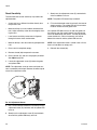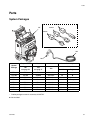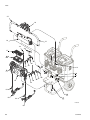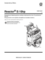
1
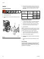
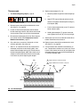
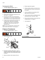
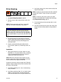
Instructions-Parts
Reactor® E-10hp
332144C
EN
For spraying or dispensing polyurea coatings and polyurethane foam. For professional
use only.
Not approved for use in explosive atmospheres or hazardous locations.
3000 psi (21 MPa, 207 bar) Maximum Working Pressure
Important Safety Instructions
Read all warnings and instructions in this
manual. Save these instructions.
ti21488a
Contents
Warnings . . . . . . . . . . . . . . . . . . . . . . . . . . . . . . . . . 3
Important Isocyanate (ISO) Information . . . . . . . . 6
Isocyanate Conditions . . . . . . . . . . . . . . . . . . . . 6
Material Self-ignition . . . . . . . . . . . . . . . . . . . . . . 6
Keep Components ISO and RES Separate . . . . 6
Moisture Sensitivity of Isocyanates . . . . . . . . . . . 6
Foam Resins with 245 fa Blowing Agents . . . . . . 6
Changing Materials . . . . . . . . . . . . . . . . . . . . . . . 7
Systems . . . . . . . . . . . . . . . . . . . . . . . . . . . . . . . . . . 8
Models . . . . . . . . . . . . . . . . . . . . . . . . . . . . . . . . . . . 8
Related Manuals . . . . . . . . . . . . . . . . . . . . . . . . . . . 9
Overview . . . . . . . . . . . . . . . . . . . . . . . . . . . . . . . . . 10
Component Identification . . . . . . . . . . . . . . . . . . . 11
Controls and Indicators . . . . . . . . . . . . . . . . . . . . 12
Heater Controls . . . . . . . . . . . . . . . . . . . . . . . . . 12
System Controls . . . . . . . . . . . . . . . . . . . . . . . . 12
Controls and Indicators . . . . . . . . . . . . . . . . . . . 13
Setup . . . . . . . . . . . . . . . . . . . . . . . . . . . . . . . . . . . . 15
Locate Reactor . . . . . . . . . . . . . . . . . . . . . . . . . 15
Electrical Requirements . . . . . . . . . . . . . . . . . . 15
Ground System . . . . . . . . . . . . . . . . . . . . . . . . . 16
Connect Fluid Hoses . . . . . . . . . . . . . . . . . . . . . 16
Connect Gun Air Hose . . . . . . . . . . . . . . . . . . . 16
Connect Main Air Supply . . . . . . . . . . . . . . . . . 16
Flush Before First Use . . . . . . . . . . . . . . . . . . . 16
Fill Wet-Cups . . . . . . . . . . . . . . . . . . . . . . . . . . 17
Fill Fluid Tanks . . . . . . . . . . . . . . . . . . . . . . . . . 17
Purge Air and Flush Fluid From Lines . . . . . . . 18
Startup . . . . . . . . . . . . . . . . . . . . . . . . . . . . . . . . . . 19
Heatup Guidelines . . . . . . . . . . . . . . . . . . . . . . 20
Heat Management Tips . . . . . . . . . . . . . . . . . . . 20
Spraying . . . . . . . . . . . . . . . . . . . . . . . . . . . . . . . . . 21
Pause . . . . . . . . . . . . . . . . . . . . . . . . . . . . . . . . . . . 22
Refill Tanks . . . . . . . . . . . . . . . . . . . . . . . . . . . . . . 22
Pressure Relief Procedure . . . . . . . . . . . . . . . . . . 23
Shutdown . . . . . . . . . . . . . . . . . . . . . . . . . . . . . . . . 23
Maintenance . . . . . . . . . . . . . . . . . . . . . . . . . . . . . . 24
Flushing . . . . . . . . . . . . . . . . . . . . . . . . . . . . . . . . . 25
Purge Hoses . . . . . . . . . . . . . . . . . . . . . . . . . . . 26
2
Troubleshooting . . . . . . . . . . . . . . . . . . . . . . . . . . . 27
Pump Control Status Codes . . . . . . . . . . . . . . . 27
DIP Switch Settings . . . . . . . . . . . . . . . . . . . . . . 29
Heat Control Diagnostic Codes . . . . . . . . . . . . . 31
Reactor Electronics . . . . . . . . . . . . . . . . . . . . . . 33
Heaters . . . . . . . . . . . . . . . . . . . . . . . . . . . . . . . 35
Proportioner . . . . . . . . . . . . . . . . . . . . . . . . . . . . 36
Repair . . . . . . . . . . . . . . . . . . . . . . . . . . . . . . . . . . . 39
Before Beginning Repair . . . . . . . . . . . . . . . . . . 39
Remove Supply Tank . . . . . . . . . . . . . . . . . . . . 39
Replace Recirc/Spray Valves . . . . . . . . . . . . . . 40
Displacement Pump . . . . . . . . . . . . . . . . . . . . . 41
Control Panel . . . . . . . . . . . . . . . . . . . . . . . . . . . 42
Motor Control . . . . . . . . . . . . . . . . . . . . . . . . . . . 44
Heater . . . . . . . . . . . . . . . . . . . . . . . . . . . . . . . . 48
Pressure Transducers . . . . . . . . . . . . . . . . . . . . 50
Drive Housing . . . . . . . . . . . . . . . . . . . . . . . . . . 51
Replace Cycle Counter Switch . . . . . . . . . . . . . 52
Electric Motor . . . . . . . . . . . . . . . . . . . . . . . . . . . 53
Motor Brushes . . . . . . . . . . . . . . . . . . . . . . . . . . 54
Fans . . . . . . . . . . . . . . . . . . . . . . . . . . . . . . . . . . 54
Tank Fluid Level Sensors . . . . . . . . . . . . . . . . . 55
Parts . . . . . . . . . . . . . . . . . . . . . . . . . . . . . . . . . . . . 57
System Packages . . . . . . . . . . . . . . . . . . . . . . . 57
E-10hp Proportioners . . . . . . . . . . . . . . . . . . . . 58
Suggested Replacement Parts . . . . . . . . . . . . . . . 74
Accessories . . . . . . . . . . . . . . . . . . . . . . . . . . . . . . 74
Dimensions . . . . . . . . . . . . . . . . . . . . . . . . . . . . . . . 74
Technical Data . . . . . . . . . . . . . . . . . . . . . . . . . . . . 75
Notes . . . . . . . . . . . . . . . . . . . . . . . . . . . . . . . . . . . . 77
Graco Standard Warranty . . . . . . . . . . . . . . . . . . . 78
332144C
Warnings
Warnings
The following warnings are for the setup, use, grounding, maintenance, and repair of this equipment. The exclamation point symbol alerts you to a general warning and the hazard symbols refer to procedure-specific risks. When
these symbols appear in the body of this manual or on warning labels, refer back to these Warnings. Product-specific
hazard symbols and warnings not covered in this section may appear throughout the body of this manual where
applicable.
WARNING
ELECTRIC SHOCK HAZARD
This equipment must be grounded. Improper grounding, setup, or usage of the system can cause electric shock.
• Turn off and disconnect power cord before servicing equipment.
• Connect only to grounded electrical outlets.
• Use only 3-wire extension cords.
• Ensure ground prongs are intact on power and extension cords.
• Do not expose to rain. Store indoors.
TOXIC FLUID OR FUMES HAZARD
Toxic fluids or fumes can cause serious injury or death if splashed in the eyes or on skin, inhaled, or
swallowed.
• Read MSDSs to know the specific hazards of the fluids you are using.
• Store hazardous fluid in approved containers, and dispose of it according to applicable guidelines.
PERSONAL PROTECTIVE EQUIPMENT
Wear appropriate protective equipment when in the work area to help prevent serious injury, including
eye injury, hearing loss, inhalation of toxic fumes, and burns. This protective equipment includes but is
not limited to:
• Protective eyewear, and hearing protection.
• Respirators, protective clothing, and gloves as recommended by the fluid and solvent manufacturer.
SKIN INJECTION HAZARD
High-pressure fluid from gun, hose leaks, or ruptured components will pierce skin. This may look like just
a cut, but it is a serious injury that can result in amputation. Get immediate surgical treatment.
• Engage trigger lock when not spraying.
• Do not point gun at anyone or at any part of the body.
• Do not put your hand over the spray tip.
• Do not stop or deflect leaks with your hand, body, glove, or rag.
• Follow the Pressure Relief Procedure when you stop spraying and before cleaning, checking, or
servicing equipment.
• Tighten all fluid connections before operating the equipment.
• Check hoses and couplings daily. Replace worn or damaged parts immediately.
332144C
3
Warnings
WARNING
FIRE AND EXPLOSION HAZARD
Flammable fumes, such as solvent and paint fumes, in work area can ignite or explode. To help prevent
fire and explosion:
• Use equipment only in well ventilated area.
• Eliminate all ignition sources; such as pilot lights, cigarettes, portable electric lamps, and plastic drop
cloths (potential static arc).
• Keep work area free of debris, including solvent, rags and gasoline.
• Do not plug or unplug power cords, or turn power or light switches on or off when flammable fumes
are present.
• Ground all equipment in the work area. See Grounding instructions.
• Use only grounded hoses.
• Hold gun firmly to side of grounded pail when triggering into pail. Do not use pail liners unless they
are antistatic or conductive.
• Stop operation immediately if static sparking occurs or you feel a shock. Do not use equipment
until you identify and correct the problem.
• Keep a working fire extinguisher in the work area.
THERMAL EXPANSION HAZARD
Fluids subjected to heat in confined spaces, including hoses, can create a rapid rise in pressure due to
the thermal expansion. Over-pressurization can result in equipment rupture and serious injury.
• Open a valve to relieve the fluid expansion during heating.
• Replace hoses proactively at regular intervals based on your operating conditions.
PRESSURIZED ALUMINUM PARTS HAZARD
Use of fluids that are incompatible with aluminum in pressurized equipment can cause serious chemical
reaction and equipment rupture. Failure to follow this warning can result in death, serious injury, or property damage.
• Do not use 1,1,1-trichloroethane, methylene chloride, other halogenated hydrocarbon solvents or
fluids containing such solvents.
• Many other fluids may contain chemicals that can react with aluminum. Contact your material supplier for compatibility.
4
332144C
Warnings
WARNING
EQUIPMENT MISUSE HAZARD
Misuse can cause death or serious injury.
• Do not operate the unit when fatigued or under the influence of drugs or alcohol.
• Do not exceed the maximum working pressure or temperature rating of the lowest rated system
component. See Technical Data in all equipment manuals.
• Use fluids and solvents that are compatible with equipment wetted parts. See Technical Data in all
equipment manuals. Read fluid and solvent manufacturer’s warnings. For complete information
about your material, request MSDS from distributor or retailer.
• Do not leave the work area while equipment is energized or under pressure.
• Turn off all equipment and follow the Pressure Relief Procedure when equipment is not in use.
• Check equipment daily. Repair or replace worn or damaged parts immediately with genuine manufacturer’s replacement parts only.
• Do not alter or modify equipment. Alterations or modifications may void agency approvals and create
safety hazards.
• Make sure all equipment is rated and approved for the environment in which you are using it.
• Use equipment only for its intended purpose. Call your distributor for information.
• Route hoses and cables away from traffic areas, sharp edges, moving parts, and hot surfaces.
• Do not kink or over bend hoses or use hoses to pull equipment.
• Keep children and animals away from work area.
• Comply with all applicable safety regulations.
MOVING PARTS HAZARD
Moving parts can pinch, cut or amputate fingers and other body parts.
• Keep clear of moving parts.
• Do not operate equipment with protective guards or covers removed.
• Pressurized equipment can start without warning. Before checking, moving, or servicing equipment,
follow the Pressure Relief Procedure and disconnect all power sources.
BURN HAZARD
Equipment surfaces and fluid that’s heated can become very hot during operation. To avoid severe
burns:
• Do not touch hot fluid or equipment.
332144C
5
Important Isocyanate (ISO) Information
Important Isocyanate (ISO) Information
Isocyanates (ISO) are catalysts used in two component materials.
Isocyanate Conditions
Spraying or dispensing materials containing isocyanates creates potentially harmful mists, vapors, and
atomized particulates.
Read material manufacturer’s warnings and material
MSDS to know specific hazards and precautions
related to isocyanates.
Prevent inhalation of isocyanate mists, vapors, and
atomized particulates by providing sufficient ventilation in the work area. If sufficient ventilation is not
available, a supplied-air respirator is required for
everyone in the work area.
To prevent contact with isocyanates, appropriate personal protective equipment, including chemically
impermeable gloves, boots, aprons, and goggles, is
also required for everyone in the work area.
Material Self-ignition
Some materials may become self-igniting if applied
too thick. Read material manufacturer’s warnings and
material MSDS.
Keep Components ISO and RES
Separate
Cross-contamination can result in cured material in
fluid lines which could cause serious injury or damage
equipment. To prevent cross-contamination:
• Never interchange ISO and RES wetted parts.
• Never use solvent on one side if it has been contaminated from the other side.
6
Moisture Sensitivity of
Isocyanates
Exposure to moisture (such as humidity) will cause ISO
to partially cure; forming small, hard, abrasive crystals,
which become suspended in the fluid. Eventually a film
will form on the surface and the ISO will begin to gel,
increasing in viscosity.
NOTICE
Partially cured ISO will reduce performance and the
life of all wetted parts.
•
Always use a sealed container with a desiccant
dryer in the vent, or a nitrogen atmosphere. Never
store ISO in an open container.
•
Keep the ISO pump wet cup or reservoir (if
installed) filled with appropriate lubricant. The
lubricant creates a barrier between the ISO and
the atmosphere.
•
Use only moisture-proof hoses compatible with
ISO.
•
Never use reclaimed solvents, which may contain
moisture. Always keep solvent containers closed
when not in use.
•
Always lubricate threaded parts with an appropriate lubricant when reassembling.
NOTE: The amount of film formation and rate of crystallization varies depending on the blend of ISO, the
humidity, and the temperature.
Foam Resins with 245 fa
Blowing Agents
Some foam blowing agents will froth at temperatures
above 90°F (33°C) when not under pressure, especially
if agitated. To reduce frothing, minimize preheating in a
circulation system.
332144C
Important Isocyanate (ISO) Information
Changing Materials
NOTICE
Changing the material types used in your equipment
requires special attention to avoid equipment damage
and downtime.
•
When changing materials, flush the equipment
multiple times to ensure it is thoroughly clean.
•
Always clean the fluid inlet strainers after flushing.
•
Check with your material manufacturer for chemical compatibility.
•
When changing between epoxies and urethanes
or polyureas, disassemble and clean all fluid components and change hoses. Epoxies often have
amines on the RES (hardener) side. Polyureas
often have amines on the RES (resin) side
332144C
7
Systems
Systems
Part
APT100
P2T100
APT900
APT901
APT902
P2T900
P2T901
P2T902
24T900
24T901
24T902
Maximum
Working
Pressure,
psi
(MPa, bar)
3000
(21, 207)
3000
(21, 207)
3000
(21, 207)
3000
(21, 207)
3000
(21, 207)
3000
(21, 207)
3000
(21, 207)
3000
(21, 207)
3000
(21, 207)
3000
(21, 207)
3000
(21, 207)
Gun
Volts
Proportioner
Model
Unheated
Hose
35 ft (10.6 m)
Cord
Adapter
Model
Part
120 V
24T100
25R000
---
Fusion® Air Purge
249810
120 V
24T100
25R000
---
PROBLER® P2
GCP2RA
230 V
24R900
25R000
North
America
Fusion® Air Purge
249810
230 V
24R900
25R000
Europe
Fusion® Air Purge
249810
230 V
24R900
25R000
Fusion® Air Purge
249810
230 V
24R900
25R000
Australia/
Asia
North
America
PROBLER® P2
GCP2RA
230 V
24R900
25R000
Europe
PROBLER® P2
GCP2RA
230 V
24R900
25R000
PROBLER® P2
GCP2RA
230 V
24R900
---
Australia/
Asia
North
America
---
---
230 V
24R900
---
Europe
---
---
230 V
24R900
---
Australia/
Asia
---
---
Models
The model no., series letter, and serial no. are located on the back of the cart. For faster assistance, please have that
information ready before calling Customer Service.
Bare
Proportioner
Part, Series
Volts
24T100, A
120 V
24R900, A
230 V
* Electrical
Connection
Maximum
Working
Pressure,
psi (MPa, bar)
20 A cord
(motor)
3000
(21, 207)
20 A cord
(heaters)
15 A cord
(motor)
3000
(21, 207)
15 A cord
(heaters)
Approvals
9902471
Conforms to ANSI/UL
Std. 499 Certified to
CAN/CSA Std.
C22.2 No. 88
* See page 15 for detailed electrical requirements.
8
332144C
Related Manuals
Related Manuals
The following manuals are for Reactor E-10hp components and accessories. Some are supplied with your package,
depending on its configuration. Manuals are also available at www.graco.com.
Displacement Pump
Part No.
Description
311076
Instruction-Parts Manual (English)
Fusion Air Purge Spray Gun
Part No.
Description
309550
Instruction-Parts Manual (English)
Probler P2 Spray Gun
Part No.
Description
313213
Instruction-Parts Manual (English)
Probler P2 Recirculation Kit
Part No.
Description
406842
Instruction-Parts Manual (English)
Lift Ring Kit
Part No.
332977
332144C
Description
Instruction-Parts Manual (English)
9
Overview
Overview
The Reactor E-10hp is a portable, electric-powered, 1:1
mix ratio proportioner for use with:
The Reactor E-10hp has two recirculation speeds, slow
and fast, and an adjustable pressure output.
•
•
•
Slow Recirculation
Polyurea
Polyurea hybrid coatings
Polyurethane foam
Material may be applied with impingement mix spray
guns.
The Reactor E-10hp is gravity-fed from 6 gal. (22.7 liter)
supply tanks mounted on the unit.
Severe duty, positive displacement reciprocating piston
pumps meter fluid flow to the gun for mixing and applying. When set to recirculation mode, Reactor E-10hp will
circulate fluids back to the supply tanks.
The Reactor E-10hp uses primary heating rods and
boost heating rods, for each fluid, and an insulated hose
bundle with circulation return hoses. This allows the
hoses and gun to be preheated to the desired temperature before spraying. The boost heating rods are used
during circulation mode to reduce heatup time. Digital
displays show the temperatures of the two fluids.
•
•
•
•
Slow circulation results in a higher temperature
transfer in the heater, so hoses and gun heat up
quicker.
Good for touchup or low flow spraying, up to moderate temperature.
Not used to circulate full tanks up to temperature.
Use with 245 fa blowing agent foams, to minimize
heat returned to tank and reduce frothing.
Fast Recirculation
•
•
•
Use to support higher flow rates or higher temperatures by preheating the tanks.
Agitates fluid within tanks, to avoid heating only the
fluid at the top of the tank.
Use for flushing.
Pressure Adjust
Electronic controls monitor fluid pressures, drive the
motor, and alerts the operator if errors occur. See
Motor/Pump Status Codes, page 14, for further information.
10
Automatically maintains selected pressure output for
dispensing or spraying.
332144C
Component Identification
Component Identification
Key for FIG. 1
N
P
Q
R
S
T
Desiccant Dryer
Recirculation Tubes
Air Line Inlet (quick-disconnect fitting)
Outlet Hose Connections
Return Hose Connections
Fluid Temperature Sensors (located on heater
assembly, under shroud)
U Hose Rack and Control Shield
V Fluid Inlet Ball Valves (each side)
W Fluid Inlet Strainers (each side)
X Power Cords (not shown)
Y Fluid Temperature Gauges (each side)
Z Air Filter/Moisture Separator
A
B
C
D
E
F
G
H
J
K
L
Supply Tank (ISO)
Supply Tank (RES)
Pump (ISO)
Pump (RES)
Heater (under shroud)
Fluid Pressure Gauges
Recirc/Spray and Overpressure Relief Valves
Tank Level Sensors (bottom of tanks)
Control Panel; see FIG. 2, page 12
Electric Motor and Drive Housings
Insulated Hose Bundle (includes circulation return
hoses)
M Fusion Air Purge Spray Gun
J
U
B
P
G
A
F
S
R
N
E
S
G
R
K
P
D
Y
L
H
ti21488a
V
Q
C
W
FIG. 1: Component Identification
332144C
Z
M
11
Controls and Indicators
Controls and Indicators
See Controls and Indicators identification table, page
13.
NOTICE
To prevent damage to soft key buttons, do not press
the buttons with sharp objects such as pens, plastic
cards, or fingernails.
Heater Controls
AL
AM
AA
AE
AB
AN
AF
AC
AD
AR
AP AO
AS
AG
°F
AH
°C
AJ
AK
FIG. 2. Heater Controls and Indicators
System Controls
AW
AY
AX
-
STATUS
1
I
AT
0
I
2
3
4
5
6
++
7
AV
8
--
9
10
AU
FIG. 3. System Controls and Indicators
12
332144C
Controls and Indicators
Controls and Indicators
Key
Name
Heater Controls
AA
ISO Setpoint Increase
AB
ISO Setpoint Decrease
AC
RES Setpoint Increase
AD
RES Setpoint Decrease
AE
ISO Heater On/Off Key
AF
RES Heater On/Off Key
AG
Actual Temperature Key
AH
Target Temperature Key
AJ
AK
AL
Temperature Scale Key °F
Temperature Scale Key °C
Temperature Display
Heater Indicators
AM
ISO Heater Activity
AN
RES Heater Activity
Description
Increases the temperature setpoint by one degree in the units selected
within the setpoint limits. Press target key prior to adjusting.
Decreases the temperature setpoint by one degree in the units
selected within the setpoint limits. Press target key prior to adjusting.
Increases the temperature setpoint by one degree in the units selected
within the setpoint limits. Press target key prior to adjusting.
Decreases the temperature setpoint by one degree in the units
selected within the setpoint limits. Press target key prior to adjusting.
Turns heater on or off for ISO zone. Also clears heater zone diagnostic
codes, see page 31.
Turns heater on or off for RES zone. Also clears heater zone diagnostic
codes, see page 31.
Press to display actual temperature. Press and hold to display electrical
current.
Press to display target temperature. Press and hold to display heater
control circuit board temperature.
Press to change temperature scale to degrees Fahrenheit.
Press to change temperature scale to degrees Celsius.
Show actual temperature or target temperature of heater zones,
depending on selected mode. Defaults to actual at startup. Range is
32-170°F (0-77°C) for ISO and RES.
LEDs flash when heater zones are on. The duration
of each flash shows the extent that the heater is
turned on.
LEDs flash when heater zones are on. The duration
of each flash shows the extent that the heater is
turned on.
Actual temperatures are displayed.
Target temperatures are displayed.
Indicates that temperatures are displayed in °F.
Indicates that temperatures are displayed in °C.
AO
Actual Temperatures Active
AP
Target Temperatures Active
AR
Fahrenheit Units Active
AS
Celsius Units Active
System Controls
AT
Heater Power
Enables heater control. The switch includes a 20 A circuit breaker.
AU
Motor Power
Enables motor. The switch includes a 20 A circuit breaker.
AV
Motor Pump Control Function Knob Selects operation mode / pressure setpoint. See Motor/Pump Control
Function Knob, page 14.
System Indicators
AW
Boost Heat Indicator
Indicates boost heat is active.
AX
Tank Level Indicator
See Tank Level Sensor LED, page 14.
AY
System Status Indicator
Flashes an error code if alarm or deviation is active. See Motor/Pump
Status Codes, page 14.
332144C
13
Controls and Indicators
Motor/Pump Control Function Knob
Heater Control Diagnostic Codes
Use knob (AV) to select desired function.
Heater control diagnostic codes appear on the temperature display. These alarms turn off heat.
Icon
Setting
Function
Stop/Park
Stops motor and automatically parks pumps.
Slow Recirc
Slow recirculation speed.
Fast Recirc
Fast recirculation speed.
Table 2: Heater Control Diagnostic Codes
Code
Name
Alarm Zone
01
High fluid temperature
Individual
02
High zone current
Individual
03
No zone current with heater on
Individual
04
Thermocouple not connected
Individual
05
High controller temperature
Individual
06
No communications with zone
pod
Individual
Motor/Pump Status Codes
09
Display is missing
Individual
If error occurs, status indicator (AY) will blink 1 to 19
times to indicate status code, pause, then repeat, or will
blink other active error codes. See TABLE 1 for a brief
description of status codes.
99
No communication with heater
control module
Individual
Pressure
Adjust
Adjusts fluid pressure to
gun in spray mode.
Table 1: Motor/Pump Status Codes
Tank Level Sensor LED
The tank level sensor LED (AX) is triggered when chemical is not present in either tank.
No.
Name
1
Pressure imbalance between ISO and RES sides
2
Pressure deviation from setpoint
3
Pressure transducer ISO failure
> 1 gallon
Off
4
Pressure transducer RES failure
< 1 gallon
Flashing
5
Excessive current draw
6
High motor temperature
7
No cycle counter switch input
8
High cycle rate deviation (more than 1.0 GPM)
Table 3: Tank Level Indicator (AX)
Chemical
Status
High cycle rate shutdown (more than 1.1 GPM)
9
Low tank level
10
Not used
11
Locked motor rotor
12
Motor controller bus overvoltage
13
Motor controller bus undervoltage
14
Motor controller high temperature
15-19 Motor controller fault
NOTE: The default is to shut down if a status code indication occurs.
14
332144C
Setup
Setup
Locate Reactor
1. Locate Reactor on a level surface.
To avoid electric shock, always unplug both cords
before servicing Reactor and wait one minute.
2. Do not expose Reactor to rain.
Electrical Requirements
Heater Power
1
Improper wiring may cause electric shock or other
serious injury if work is not performed properly. All
electrical wiring must be done by a qualified
electrician and comply with all local codes and
regulations.
2
TI7061a
1. Connect Reactor to the correct power source for
your model. See Table 4. Power cords must be connected to two separate, dedicated circuits. See FIG.
4.
2. Some models include cord adapters for use outside
North America. Connect the appropriate adapter to
the unit’s power cord before connecting to your
power source.
1
Motor Power
1
Ensure no other high amp loads are connected while running
Reactor.
2
To verify separate circuits, plug in Reactor or a worklight and
cycle breakers on and off.
FIG. 4: Use Two Separate Circuits
Table 4: Electrical Requirements
Model
Required Power
Source
230 V, 1 phase, 50/60 Two separate, dediHz, two 15 ft (4.5 m)
cated circuits rated at
power cords
minimum of 15 A
each
Power Cord
Connectors
Supplied Local Adapters
NEMA 6-15P
(North America)
Euro CEE74
Two IEC 3-20 C20
Plugs
(Europe)
YP-39 AS3112
120V, 50/60 Hz, two
15 ft (4.5 m) power
cords
Two separate dedicated circuits rated at
minimum of 20 A
each
(Australia/Asia)
Two NEMA
5-20P Plugs
Table 5: Extension Cord Requirements
Required Wire Size
Model
All models
Up to 50 ft (15 m)
Up to 100 ft (30 m)
AWG 12
AWG 10
NOTE: Cords must be 3-conductor grounded, rated for your environment.
332144C
15
Setup
Ground System
2. Connect recirculation hoses from gun recirculation
ports to connections (S).
The equipment must be grounded to reduce the risk
of static sparking and electric shock. Electric or static
sparking can cause fumes to ignite or explode.
Improper grounding can cause electric shock.
Grounding provides an escape wire for the electric
current.
S
R
(RES)
Reactor: grounded through power cord.
R
S
(ISO)
Generator (if used): follow your local code. Start and
stop generator with power cord(s) disconnected.
Spray gun: grounded through the supplied fluid hoses,
connected to a properly grounded Reactor. Do not operate without at least one grounded fluid hose.
Object being sprayed: follow your local code.
Solvent pails used when flushing: follow your local
code. Use only metal pails, which are conductive,
placed on a grounded surface. Do not place pail on a
nonconductive surface, such as paper, plastic, or cardboard, which interrupts grounding continuity.
To maintain grounding continuity when flushing or
relieving pressure: hold a metal part of spray gun
firmly to the side of a grounded metal pail, then trigger
gun.
Connect Fluid Hoses
1. Connect fluid supply hoses to outlet hose connections (R, FIG. 5). Red hoses for ISO, blue for RES.
Fittings are sized to prevent connection errors. Connect other end of hoses to ISO and RES inputs of
gun.
NOTE: Probler guns use recirc accessory kit 24E727.
Air
FIG. 5
Connect Gun Air Hose
1. Connect gun air hose to the gun air input and to the
air filter outlet (Z). If you are using more than one
hose bundle, join the air hoses with the nipple provided with the hose bundle.
2. On units with Fusion guns, connect the supplied ball
valve and quick-disconnect coupler to the gun air
hose, then connect the coupler to the gun air fitting.
Connect Main Air Supply
Connect the main air supply to the quick disconnect fitting (Q) on the unit. Air supply hose must be at least
5/16 in. (8 mm) ID up to 50 ft (15 m) or 3/8 in. (10 mm)
ID up to 100 ft (30 m).
NOTE: Air Filter/Moisture Separator (Z) is equipped with
an automatic moisture drain.
Flush Before First Use
The Reactor is tested with a plasticizer oil at the factory.
Flush out the oil with a compatible solvent before spraying. See Flushing, page 25.
16
332144C
Setup
Fill Wet-Cups
1. Lift hose rack. Remove tank cover and pour ISO
into tank (red side, with desiccant filter in cover).
Keep the felt washers in the pump wet-cups saturated
with Graco ISO pump oil, Part No. 217374. The lubricant
creates a barrier between the ISO and the atmosphere.
Pump rod and connecting rod move during operation.
Moving parts can cause serious injury such as
pinching or amputation. Keep hands and fingers
away from wet-cup during operation. Shut off Motor
Power
before filling wet-cup.
Fill wet-cups through slots in plate, or loosen screws
and swing plate aside.
Replace cover
1
.
RES
ISO
1
Add thin coating of grease lubricant to tank o-ring
if lid is difficult to assemble to tank.
NOTE: Desiccant filter is blue when fresh, and turns
pink when saturated. Be sure shipping plugs are
removed from openings on desiccant filter.
2. Remove tank cover and pour resin into RES tank
(blue side). Replace cover
1
.
Fill Fluid Tanks
NOTICE
To prevent cross-contamination of fluids and equipment parts, never interchange (isocyanate) and
(resin) parts or containers.
Have at least two 5 gal. (19 liter) pails to transfer fluid
from drums to supply tanks. Label one pail “ISO” and
the other “RES”, using the red and blue labels provided. Always double-check which material you have
before pouring it in the supply tanks. Pouring is easier
if pails are not filled to the top.
Open only one supply tank at a time, to avoid splashing material from one tank into the other when filling.
NOTE: Using a drill and mixing blade, mix filled or separated materials in the pail before adding to the tanks.
Material left in the tanks overnight may need to be
remixed in the tanks.
332144C
17
Setup
Purge Air and Flush Fluid From
Lines
To avoid fire and explosion:
5. Turn on Motor Power. System status indicator (AY)
should turn on.
6. Set Recirc/Spray valves to Recirc.
• Flush equipment only in a well-ventilated area.
• Ensure main power is off and heater is cool before
flushing.
• Do not turn on heater until fluid lines are clear of
solvent.
1. Remove both recirculation tubes (P) from the tanks
and secure each one in a dedicated waste container.
ti21495a
7. Set function knob to Slow Recirc
or Fast Recirc
.
-
STATUS
P
1
0
2
3
-
STATUS
1
4
2
3
0
5
4
5
6
+
6
+
7
8
-
OR
9
10
7
8
-
9
10
ti21489a
8. When clean fluids exit both recirculation tubes (P),
2. Set function knob to Stop/Park
.
set function knob to Stop/Park
STATUS
1
0
2
3
.
4
5
1
0
6
+
2
3
4
5
6
7
+
7
8
-
8
-
9
9
10
10
ti21490a
3. Plug in power cords(s). See Table 2, page 15.
9. Replace recirculation tubes in supply tanks.
4. Open both pump fluid inlet valves (V, shown in open
position).
V
ti21917a
18
332144C
Startup
Startup
d. Press
Heated fluid can cause equipment surfaces to
become very hot. To avoid severe burns:
to display actual temperatures.
5. Circulate through heater until temperature readouts
display desired temperature. See Table 6.
• Do not operate Reactor without all covers and
shrouds in place.
• Do not touch hot fluid or equipment.
• Allow equipment to cool completely before
touching it.
6. Adjust heat controls as necessary for a stable spray
temperature.
Table 6: Approximate heatup time for starting a cold
machine with 5 gallons (19 liters) per side
1. Perform Setup, page 15.
120 V
2. Set function knob to Slow Recirc
or Fast Recirc
. See Heatup Guidelines, page 20, then continue with steps 3-6.
1
0
2
3
1
4
0
5
2
3
4
+
6
+
7
8
-
OR
9
10
7
8
-
125°F (52°C)
170°F (77°C)
35 ft (10.7 m) Hose
(1 bundle)
15 minutes
40 minutes
10 minutes
20 minutes
NOTE: Heatup times are based on 70°F (21°C) starting
material temperature and 70°F (21°C) ambient temperature.
5
6
Fluid Spray Target
Temperature
230 V
9
10
ti21489a
3. Turn on Heater Power.
NOTE: Different fluids will absorb heat at different rates.
When refilling a warm machine, heatup times will be
less.
4. Set temperatures:
a. Press
°F
or
°C
to change temperature
scale.
b. Press
c.
To set
press
to display target temperatures.
heat zone target temperature,
or
until display shows
desired temperature. Repeat for
332144C
zone.
19
Startup
Heatup Guidelines
Heat Management Tips
The fluids must be circulated from the pumps through
the heater, hoses, and back to the tanks to ensure warm
fluids are supplied to the gun.
•
Heaters perform better with lower flow rates or
smaller mix modules.
•
Triggering the gun for short periods helps maintain
efficient heat transfer, keeping material at the
desired temperature. Triggering the gun for a long
period may not allow enough heating time, depending on material temperature in tanks.
•
If temperature displays fall below acceptable limits,
Slow Recirculation
•
•
Slow Recirc results in a higher temperature transfer
in the heater, so hoses and gun heat up quicker.
Good for touchup or low flow spraying, up to moderate temperature.
set function knob to Slow Recirculation
and circulate again to bring temperatures back up.
Fast Recirculation
Fast Recirc keeps heaters on full-time to bring fluid
tanks up to temperature. The higher your flow rate, the
more heat needed in the tanks before spraying.
•
For 230 V systems: Use Fast Recirc until pump inlet
fluid temperature gauges (Y) are within 45°F (25°C)
of target outlet temperature.
•
For 120 V systems: Use Fast Recirc until pump inlet
fluid temperature gauges (Y) are within 30°F (17°C)
of target temperature.
•
Volume in tanks: Use only what you need. For
example, 2.5 gal. (10 l) in each tank will heat up
almost twice as fast as 5 gal. (20 l).
•
Mixes fluid within tanks, to avoid heating only the
fluid at the top of the tank.
•
Use for flushing.
20
•
Each 35 ft (10.7 m) hose bundle adds about 5 minutes to heatup time, with most materials. Maximum
recommended hose length is 105 ft (32 m).
•
For a quicker start, do initial heatup circulation with
the tanks 1/4 to 1/3 filled, then add more material.
332144C
Spraying
Spraying
NOTE: Air is supplied to spray gun with gun piston
safety lock or trigger safety lock engaged and gun fluid
manifold valves closed (if present).
4. Check fluid pressure gauges to ensure proper pressure balance. If imbalanced, reduce pressure of
higher component by slightly turning Recirc/Spray
valve for that component toward Recirc, until
gauges show balanced pressures. The pressure
imbalance alarm (Status Code 1) is inactive for 10
seconds after entering spray pressure mode, to
allow time to balance pressures.
In this example, RES side
pressure is higher, so use
the RES side valve to balance pressures.
Probler
Fusion
ti21493a
1. Set function knob to Stop/Park
status indicator LED is on.
2
1
3
. Verify system
NOTE: Watch gauges for 10 seconds to be sure pressure holds on both sides and pumps are not moving.
4
0
5
5. Open gun fluid manifold valves (impingement mix
guns only).
6
+
7
8
-
9
10
ti21490a
2. Set Recirc/Spray valves to Spray.
Fusion
Probler
NOTE: On impingement guns, never open fluid manifold
valves or trigger gun if pressure are imbalanced.
ti21491a
6. Disengage piston safety lock or trigger safety lock.
3. Turn function knob to Pressure Adjust
. Keep
turning to the right until fluid pressure gauges show
desired pressure.
1
0
2
3
4
5
6
+
7
Fusion
8
-
Probler
9
10
ti21492a
7. Test spray onto cardboard or plastic sheet. Verify
that material fully cures in the required length of
time, and is the correct color. Adjust pressure and
temperature to get desired results. Equipment is
ready to spray.
332144C
21
Pause
Pause
Refill Tanks
To bring the hose and gun back to spray temperature
after a brief break, use the following procedure.
Material can be added to the tanks at any time. See Fill
Fluid Tanks, page 17.
1. Engage piston safety lock or trigger safety lock.
NOTE: If you are operating at high temperatures or flow
rates, follow Pause instructions to bring tanks up to temperature.
NOTICE
Fusion
Probler
2. Set function knob to Slow Recirc
1
0
2
3
To prevent cross-contamination of fluids and equipment parts, never interchange ISO and RES parts or
containers.
.
Have at least two 5 gal. (19 liter) pails to transfer fluid
from drums to supply tanks. Label one pail “ISO” and
the other “RES”, using the red and blue labels provided. Always double-check which material you have
before pouring it in the supply tanks. Pouring is easier
if pails are not filled to the top.
4
5
6
+
7
8
-
9
10
ti21494a
3. Set Recirc/Spray valves to Recirc until temperature
readouts come back up.
Open only one supply tank at a time, to avoid splashing material from one tank into the other when filling.
ti21495a
4. If you stop spraying for more than 2 minutes when
using an impingement mix gun, close gun fluid
valves. Doing this will keep the internal parts of the
gun cleaner and prevent crossover.
Fusion
22
Probler
332144C
Pressure Relief Procedure
Pressure Relief
Procedure
Shutdown
Follow the Pressure Relief Procedure whenever
you see this symbol.
NOTE: For longer breaks (more than 10 minutes) use
the following procedure. If you will be shutdown for more
than 3 days, first see Flushing, page 25.
1. Shut off Heater Power.
This equipment stays pressurized until pressure is
manually relieved. To help prevent serious injury
from pressurized fluid, such as skin injection,
splashing fluid and moving parts, follow the Pressure
Relief Procedure when you stop spraying and before
cleaning, checking, or servicing the equipment.
2. Shut off Motor Power.
1. Engage piston safety lock or trigger safety lock.
3. Follow all steps of Pressure Relief Procedure,
page 23.
4. Close gun fluid valves ISO and RES. Doing this will
keep the internal parts of the gun cleaner and prevent crossover.
Probler
Fusion
2. Set function knob to Stop/Park
1
0
2
3
.
4
5
6
+
7
8
-
Fusion
9
10
Probler
ti21490a
3. Turn Recirc/Spray valves to Recirc. Fluid will be
dumped to supply tanks. Pumps will move to the
bottom of their stroke. Ensure gauges drop to 0.
5. Refer to your separate gun manual and perform
Shutdown procedure.
ti21495a
332144C
23
Maintenance
Maintenance
•
Check pump wet-cups fluid level daily, page 17.
•
Throat u-cup is not adjustable. Do not overtighten
packing nut/wet-cup.
•
Keep component ISO from exposure to moisture in
atmosphere, to prevent crystallization.
•
Wipe supply tank lid o-ring, inner rim, and inner tank
walls daily to prevent ISO crystallization. Keep film
of grease on o-ring and inside of lid.
•
Check desiccant filter weekly. Filter is blue when
fresh, and turns pink when saturated.
•
Remove plug (X) and clean fluid inlet strainer (S) as
needed. Always clean the fluid inlet strainers after
flushing.
S
X
ti21836a
•
Generally, flush if you will shutdown for more than
three days. Flush more often if material is moisture
sensitive and humidity is high in the storage area, or
if material may separate or settle out over time.
•
If using an impingement mix gun, close gun fluid
valves when not spraying. Doing this will keep the
internal parts of the gun cleaner and prevent crossover. Clean gun mix chamber ports and check valve
screens regularly. See gun manual.
Fusion
•
24
Probler
If using an Fusion Air Purge impingement mix gun,
always grease the gun after use until purge air carries grease mist out the front of the gun. Use Part
No. 117773 Grease. See gun manual.
332144C
Flushing
Flushing
3. Shut off Heater Power. Allow system to cool.
To avoid fire and explosion:
• Flush equipment only in a well-ventilated area.
• Ensure main power is off and heater is cool before
flushing.
• Do not turn on heater until fluid lines are clear of
solvent.
4. Remove recirculation tubes (P) from supply tanks
and place in original containers or waste containers.
P
•
Generally, flush if you will be shut down for more
than 3 days. Flush more often if material is moisture
sensitive and humidity is high in the storage area, or
if material may separate or settle out over time.
•
Flush out old fluid with new fluid, or flush out old
fluid with a compatible solvent before introducing
new fluid.
•
Use the lowest possible pressure when flushing.
•
Always leave some type of fluid in system. Do not
use water.
•
For long term storage, flush out the solvent with a
storage fluid such as Bayer Mesamoll plasticizer or,
at minimum, clean motor oil.
5. Turn Recirc/Spray valves to Recirc.
ti21495a
1. Engage piston safety lock or trigger safety lock.
Close fluid valves ISO and RES. Leave air on.
6. Set function knob to Fast Recirc
. Pump material from supply tanks until no more comes out.
2
1
3
4
0
5
6
+
7
8
-
9
ti31496a
10
Probler
Fusion
7. Set function knob to Stop/Park
.
STATUS
1
0
2
3
4
5
6
2. Set function knob to Stop/Park
1
0
2
.
+
7
8
-
9
3
4
10
5
ti21490a
6
+
7
8
-
9
10
ti21490a
332144C
8. Wipe out any remaining material from the supply
tanks. Fill each supply tank with 1-2 gal. (3.8-7.6 l)
of solvent recommended by your material manufacturer.
25
Flushing
9. Set function knob to Fast Recirc
. Pump solvent
through system to waste containers.
2
1
3
5
6
+
7
8
-
.
13. Solvent flushing is a two step process. Go back to
step 4, drain solvent, and flush again with fresh solvent.
4
0
12. Set function knob to Stop/Park
9
10
ti31496a
10. When nearly clear solvent comes from recirculation
tubes, set function knob to Stop/Park
recirculation tubes toSTATUS
supply tanks.
2
1
3
. Return
4
0
5
6
+
14. Leave unit filled with solvent, plasticizer, clean
motor oil, or refill supply tanks with new material and
reprime.
NOTE: Never leave the unit dry unless it has been disassembled and cleaned. If fluid residue dries in the
pumps, the ball checks may stick the next time you use
the unit.
7
8
-
9
10
ti21490a
11. Set function knob to Fast Recirc
. Circulate solvent through system for 10-20 minutes to ensure
thorough cleaning.
1
0
2
3
4
5
6
+
7
8
-
9
10
ti31496a
NOTE: To flush gun, refer to gun instruction manual.
Purge Hoses
Disconnect hoses from gun and secure back into the
tanks for thorough cleaning with solvent.
•
Turn Recirc/Spray valve ISO to Spray.
•
Open gun into waste ISO container.
•
Set function knob to Slow Recirc
flushed.
•
•
Set function knob to Stop/Park
Repeat for RES side.
26
until hose is
.
332144C
Troubleshooting
Troubleshooting
Pump Control Status Codes
Determine the status code by counting the number of
times the system status indicator blinks. The status indicator will blink 1-19 times to indicate a status code.
Multiple active status codes are separated by a longer
duration pause.
To turn off automatic shutdown and/or change pressure
tolerances for status code 2, see DIP Switch Settings,
page 29.
Deviation can occur if power is turned on if function
knob (AV) is not set to Park/Off. Leave knob in Park/Off
mode until status indicator LED turns on.
Status Code 1: Pressure Imbalance
Status Code 3: Pressure Transducer ISO
Failure
NOTE: The unit does not check for pressure imbalance
at setpoints less than 300 psi (2.1 MPa, 21 bar).
1. Check transducer ISO electrical connection (J11) at
board, page 45.
NOTE: The unit does not check for pressure imbalance
for 10 sec after entering pressure mode.
Unit senses pressure imbalance between components
ISO and RES, and warns or shuts down, depending on
settings of DIP switches 1 and 2. To turn off automatic
shutdown and/or tighten pressure tolerances for status
code 1, see DIP Switch Settings, page 29.
1. Reduce pressure of higher component by slightly
turning Recirc/Spray valve for that component
toward Recirc, until gauges show balanced pressures.
In this example, RES side
pressure is higher, so use
the RES side valve to balance pressures.
2. If pressure imbalance continues, see Proportioner
Troubleshooting, page 36.
Status Code 2: Pressure Deviation from
Setpoint
NOTE: The unit does not check for pressure deviation at
setpoint less than 400 psi (2.8 MPa, 28 bar).
Unit senses pressure deviation from setpoint, and warns
or shuts down, depending on settings of DIP switches 3
and 4. If equipment cannot maintain enough pressure
for a good mix with an impingement mix gun, try using a
smaller mix chamber or nozzle.
2. Reverse ISO and RES transducer electrical connections at board, page 45. If error moves to transducer
RES (Status Code 4), replace transducer ISO, page
50.
Status Code 4: Pressure Transducer RES
failure
1. Check transducer RES electrical connection (J12)
at board, page 45.
2. Reverse ISO and RES transducer electrical connections at board, page 45. If error moves to transducer
ISO (Status Code 3), replace transducer RES, page
50.
Status Code 5: Excessive Current Draw
1. Shut off unit and retry operation. Brushes may not
be fully seated.
2. Check fan operation. Elevated temperature can
cause excessive current draw.
3. Locked rotor; motor unable to turn. Replace motor,
page 53.
4. Short on control board. Replace board, page 44.
5. Worn or hung up motor brush causing arcing of
brush at commutator. Replace brushes, page 54.
6. Disconnect motor connections from the control
board. Cycle power.
a. If status code 5 is still present, replace the
board.
b. If status code 5 is not active, test motor. See
Test Motor, page 53.
332144C
27
Troubleshooting
Status Code 6: High Motor Temperature
Motor is running too hot.
1. Reduce pressure duty cycle, gun tip size, or move
Reactor to a cooler location. Allow 1 hour for cooling.
2. Check fan operation. Clean fan and motor housing.
3. Check J9 overtemperature connector on control
board.
3. Check J6 connections on control board. See Table
8, page 45.
Level Sensor
LED
Status
Green - on
Green - off
Yellow - on
Yellow - off
Sensor is powered
Sensor is not powered
Sensor detects material
Sensor does not detect material
Status Code 11: Locked Motor Rotor
Status Code 7: No Cycle Counter Switch
Input
Verify that pumps are not seized and move freely. The
motor is unable to turn. Replace motor, page 53.
Have not received input from cycle counter switch for 10
seconds after selecting Recirc mode or unit is unable to
park within 15 seconds of entering park mode.
Shut off unit and contact distributor before resuming
operation.
1. Verify that recirc valves are open and unit is set to
Recirc mode.
Status Code 12: Motor Controller
Overvoltage
2. Check cycle counter switch connection to board
(J10), see FIG. 12, page 45.
Too much voltage connected to control board. See
Technical Data, page 75, for power requirements.
3. Check that magnet (224) and cycle counter switch
(223) are in place under RES side motor end cover
(229). Replace if necessary.
Cycle power and check status indicator to see if error is
still active.
Status Code 8: High Cycle Rate
Status Code 13: Motor Controller
Undervoltage
System is spraying more than 1 gpm. System will shutdown if spraying more than 1.1 gpm.
Not enough voltage connected to control board. See
Technical Data, page 75, for power requirements.
1. Reduce pressure and/or gun tip size.
Cycle power and check status indicator to see if error is
still active.
Status Code 9: Low Tank Level
The tank level sensors sense ISO and RES material
density inside the tank, and warns or shuts down,
depending on settings of DIP switch 5. See DIP Switch
Settings, page 29.
Status Code 14: Motor Controller High
Temperature
The motor control board is too hot.
1. Add material to supply tank, if necessary.
Shutdown and move Reactor to a cooler location. Allow
1 hour for cooling.
2. Check that the tank level sensor is in contact with
the surface of the tank. Replace if necessary. See
Tank Fluid Level Sensors, page 55.
Status Code 15-19: Motor Controller Faults
28
Cycle power. If error is still present, replace board. See,
page 44.
332144C
Troubleshooting
DIP Switch Settings
To avoid electric shock, always unplug both power
cords before servicing Reactor and wait one minute.
1. Turn power off and unplug power cords from wall
outlets.
2. Remove screws and display cover (26).
26
ti21923a
3. Locate the DIP switch on the control board.
FIG. 6: DIP Switch
4. Set DIP switches to the desired positions. See DIP
Switch Settings and Functions, page 30
5. Replace display cover (26) and plug in unit.
6. Cycle power switch to activate changes to DIP
switch.
332144C
29
Troubleshooting
DIP Switch Settings and Functions
DIP Switch Settings and Functions
DIP Switch and Function
OFF
ON
DIP Switch 1
DEVIATION
DEVIATION AND
SHUTDOWN
If selected, displays a status code or displays a status code
and causes shutdown if the pressure imbalance exceeds
selection made in DIP Switch 2.
DIP Switch 2
Select pressure imbalance limits, that if exceeded, will cause See Dip Switch 1 and 2 Settings table, page
a deviation and a shutdown (if enabled).
30
DIP Switch 3
DEVIATION
*SHUTDOWN
300 psi (2.1 MPa, 21
bar)
*500 psi (3.5 MPa, 35
bar)
(25% if < 800 psi [5.6
MPa, 56 bar])
(40% if < 800 psi [5.6
MPa, 56 bar])
*DEVIATION
SHUTDOWN
DISABLE
*ENABLE
If selected, causes shutdown or displays a status code due
to deviation of pressure from setpoint exceeds selection
made in DIP Switch 4.
DIP Switch 4
Causes deviation if pressure setpoint is greater than:
DIP Switch 5
Causes shutdown or displays a status code for low fluid level
in tanks.
DIP Switch 6
Enables or disables boost heat.
DIP Switch 7
Not used
DIP Switch 8
Not used
*
Default DIP Switch Settings
DIP Switch 1 and 2 Settings
DIP
Switch 1
DIP
Switch 2
Off
30
Deviation
Shutdown
Off
300 psi (2.1
MPa, 21 bar)
---
Off
*On
500 psi (3.5
MPa, 35 bar)
---
*On
Off
300 psi (2.1
MPa, 21 bar)
500 psi (3.5
MPa, 35 bar)
*On
*On
500 psi (3.5
MPa, 35 bar)
800 psi (5.6
MPa, 56 bar)
332144C
Troubleshooting
Heat Control Diagnostic Codes
•
Failed heater element where thermocouple is
installed.
Heat control diagnostic codes appear on the temperature display.
•
Loose wire
These alarms turn off heat. Codes E03 and E04 can be
cleared by pressing
E01 Checks
.
Troubleshooting this equipment requires access to
parts that may cause electric shock or other serious
injury if work is not performed properly. Have a
qualified electrician perform all electrical
troubleshooting. Be sure to shut off all power to the
equipment before repairing.
1. To clear other codes:
2. Shut off Heater Power.
NOTE: Before checking the thermocouple, note which
zone (ISO or RES) has high fluid temperature.
3. Shut off Motor Power.
1. Check that connector B is firmly plugged into heater
control module. See Temperature Control Modules Connections, page 47.
2. Clean and re-plug connections.
4. Turn on Motor Power and Heater power to clear.
Code
Code Name
Alarm
Zone
Corrective
Action page
01
High fluid temperature
Individual
31
02
High zone current
Individual
32
03
No zone current
Individual
32
04
Thermocouple not connected
Individual
32
3. Check connections between the temperature control module and overtemperature switch, and
between the temperature control module and thermocouples. Ensure all wires are securely connected
to connector B on heater control module. See Table
7, page 32.
E01: High Fluid Temperature
•
Thermocouple ISO or RES (310) senses a fluid temperature above 260°F (71°C).
•
Overtemperature switch ISO or RES (308) senses a
fluid temperature above 230°F (110°C) and opens.
At 190°F (87°C) the switch closes again.
•
Thermocouple ISO or RES (310) fails, is damaged,
is not touching the heater element (307), or has a
poor connection to the temperature control board.
•
Overtemperature switch (308) fails in the open position.
•
The temperature control board fails to turn off any
heat zone.
•
Zone power wires or thermocouples are switched
from one zone to another.
332144C
31
Troubleshooting
4. Remove connector B from heater control module
and check continuity of thermocouples by measuring resistance across pins on the plug end.
5. Verify fluid temperature, using an external temperature sensing device.
Table 7: Connector B Resistance Measurements
120V
230V
Connector
Pin
Connector
Pin
B1
B2
B2
B2
B2
B2
1, 2
1
2
4
5
3
B1
B1
B1
B1
B1
B1
1, 2
5
6
8
9
3-4,7,10
Description
Overtemperature Switch
Thermocouple ISO, R (red)
Thermocouple ISO, Y (yellow)
Thermocouple RES, R (red)
Thermocouple RES, Y (yellow)
Unused
If temperature is too high (sensor reading is 260°F
[127°C] or above):
6. Check if thermocouples are damaged, or not contacting the heater element, see FIG. 16, page 49.
7. Check if temperature control module turns off when
equipment reaches temperature setpoint:
a. Set temperature setpoints far below displayed
temperature.
b. Turn zone on. If temperature rises steadily,
power board is failing.
c.
Verify by exchanging with another power module. See Replace Temperature Control Modules, page 46.
d. If the exchanged module does not fix the problem, the power module is not the cause.
8. Verify continuity of heater elements with an ohmmeter, see page 48.
Reading
nearly 0 ohms
4-6 ohms
4-6 ohms
N/A
E03: No zone current
When a no current error occurs, the LED on the specific
zone’s module turns red when the error is displayed.
1. Check for tripped circuit breaker on Reactor or at
power source of that zone. Replace circuit breaker if
it trips habitually.
2. Check for loose or broken connection at that zone.
3. Exchange zone module with another one. Turn
zone on and check for error (see page 46). If error
disappears, replace faulty module.
4. If E03 occurs for all zones, the contactor may not be
closing. Verify wiring from heater control to contactor coil.
E04: Thermocouple disconnected
1. Check temperature sensor connections to green
connectors (B) on temperature control module. See
Temperature Control Modules Connections,
page 47.
2. Unplug and re-plug sensor wires.
E02: High zone current
When there is a high current error, the LED on that
zone’s module will turn red while the error is displayed.
1. See Before Beginning Repair, page 39.
2. Exchange zone module with another one. Turn
zone on and check for error. If error disappears,
replace faulty module.
32
332144C
Troubleshooting
Reactor Electronics
2. Shut off Motor Power.
3. Relieve pressure, page 23.
Before performing any troubleshooting procedures:
4. Allow equipment to cool.
1. Shut off Heater Power.
5. Try the recommended solutions in the order given
for each problem, to avoid unnecessary repairs.
Also, determine that all circuit breakers, switches,
and controls are properly set and wiring is correct
before assuming there is a problem.
PROBLEM
Temperature display does not
illuminate.
CAUSE
SOLUTION
Display disconnected.
Check cable connections, page 45.
Display cable damaged or corroded.
Clean connections; replace cable if is
damaged.
Blown fuse.
Replace fuse (73) in fuse holder on
DIN rail assembly located under electronics cover (55).
Failed circuit board.
Display is failing. Replace.
Loose display cables on control
board.
Check cable connections to each display, FIG. 23 on page 72.
Failed control board (displays get
power from control board).
Remove access panel. Check if
board LED is lighted. If not, replace
board, page 44.
Inadequate power to control board.
Check that power supply meets
requirements.
Loose power cable.
Check cable connections, FIG. 23 on
page 72.
Heater power switch circuit breaker
tripped.
Display is powered from heater
power circuit breaker. Cycle heater
power off
, then on
to reset breaker.
Erratic display; display turns on and
off.
332144C
Low voltage.
Ensure input voltage is within specifications, page Technical Data, page
75.
Poor display connection.
Check cable connections, FIG. 23 on
page 72. Replace damaged cable.
Display cable damaged or corroded.
Clean connections; replace cable if is
damaged.
33
Troubleshooting
PROBLEM
CAUSE
Display does not respond properly to Poor display connection.
button pushes.
Display cable damaged or corroded.
SOLUTION
Check cable connections, FIG. 23 on
page 72. Replace damaged cable.
Clean connections, FIG. 23 on page
72. Replace damaged cable.
Ribbon cable on display circuit board Connect cable, FIG. 23 on page 72,
disconnected or broken.
or replace.
Fan not working.
34
Broken display button.
Replace, page 42.
Loose wire.
Check fan wire.
Defective fan.
Replace, page 54.
332144C
Troubleshooting
Heaters
2. Shut off Motor Power.
Before performing any troubleshooting procedures:
3. Relieve pressure, page 23.
1. Shut off Heater Power.
4. Allow equipment to cool.
Try the recommended solutions in the order given for
each problem, to avoid unnecessary repairs. Also,
determine that all circuit breakers, switches, and controls are properly set and wiring is correct before assuming there is a problem.
PROBLEM
Primary heater(s) does not heat.
CAUSE
SOLUTION
Heat turned off.
Press
or
zone
keys.
Control of primary heat is abnormal;
high temperature overshoots or E01
error occurs intermittently.
332144C
Temperature control alarm.
Check temperature display for diagnostic code, page 31.
Signal failure from thermocouple.
See E04: Thermocouple disconnected, page 32.
Failed heater element.
Check resistance of heater elements.
See Test Heater Element, page 48.
Dirty thermocouple connections.
Examine connection of thermocouples to long green plug on heater
control board. Unplug and re-plug
thermocouple wires, cleaning off any
debris. For 120V, unplug and re-plug
long green connector. For 230V,
unplug and re-plug green connector(s) B.
Thermocouple not contacting heater
element.
Loosen ferrule nut (N), push in thermocouple (310) so tip (T) contacts
heater element (307). Holding thermocouple tip (T) against heater element, tighten ferrule nut (N) 1/4 turn
past tight. See page 49 for illustration.
Failed heater element.
See Heaters, page 35.
Signal failure from thermocouple.
See E04: Thermocouple disconnected, page 32.
Thermocouple wired incorrectly.
See E04: Thermocouple disconnected, page 32. Power up zones
one at a time and verify that temperature for each zone rises.
35
Troubleshooting
Proportioner
2. Shut off Motor Power.
Before performing any troubleshooting procedures:
3. Relieve pressure, page 23.
1. Shut off Heater Power.
4. Allow equipment to cool.
Try the recommended solutions in the order given for
each problem, to avoid unnecessary repairs. Also,
determine that all circuit breakers, switches, and controls are properly set and wiring is correct before assuming there is a problem.
PROBLEM
Reactor does not operate.
CAUSE
No power.
SOLUTION
Plug in both power cords.
Cycle Motor Power and Heater
Power off
, then on
to reset both breakers.
Motor does not operate.
Power turned on while function knob
Set function knob to Stop/Park
set to a run position.
,
once status LED turns on. Then
select desired function.
Loose connection on control board.
Check connection at motor power
connections on bottom board. See
FIG. 12, page 45.
Worn brushes.
Check both sides. Replace brushes
worn to less than 1/2 in. (13 mm), see
page 54.
Broken or misaligned brush springs.
Realign or replace, page 54.
Brushes or springs binding in brush
holder.
Clean brush holder and align brush
leads for free movement.
Shorted armature.
Replace motor, page 53.
Check motor commutator for burn
Remove motor. Have motor shop
spots, black pitting, or other damage. resurface commutator, or replace
motor, page 53.
Failed control board.
Pump output low.
36
Replace board. See page 44.
Plugged fluid inlet strainer.
Clear, see page 24.
Leaking or plugged piston valve or
intake valve in displacement pump.
Check valves. See pump manual.
332144C
Troubleshooting
PROBLEM
One side doesn’t come up to pressure in spray mode.
CAUSE
Low fluid in tank.
SOLUTION
Refill.
Dirty or damaged Recirc/Spray valve. Clean or repair, page 40.
Plugged fluid inlet strainer.
Clear, see page 24.
Pump intake valve plugged or stuck
open.
Clean pump intake valve. See page
41.
Material is too viscous to pump.
Warm material before adding to
tanks.
Pressure is higher on one side when Pump intake valve partially plugged.
setting pressure with function knob.
Air in hose. Fluid is compressible.
Clean pump intake valve. See page
41.
Purge air from hose.
Unequal size hoses or unequal hose Use matching hoses, or balance
construction.
pressures before spraying.
Pressures are not balanced when
running, but pressure is generated
and holds on both strokes.
Unequal viscosities.
Change temperature setting to balance viscosities.
Change restrictor at mix point to balance back pressure.
Restriction on one side.
Clean mix module or restrictor at mix
manifold.
Clean gun check valve screens.
Fluid leak in pump packing nut area. Worn throat seals.
Replace. See pump manual.
Pressure doesn’t hold when stalled
against gun in spray mode.
Leaking Recirc/Spray valve.
Repair, page 40.
Leaking piston valve or intake valve
in displacement pump.
Repair. See pump manual.
Leaking gun shutoff.
Repair. See gun manual.
Pressure is higher on RES side dur- This is normal. RES is typically
ing startup of recirculation, especially higher viscosity than ISO until the
in High Recirc mode.
material is heated during recirculation.
No action required.
One gauge shows half as many
Loss of pressure on downstoke.
pulses as the other when pumps are
cycling.
Loss of pressure on upstoke.
Intake valve is leaking or not closing.
Clean or replace valve; see page 40.
Status indicator not lit.
Function knob is not set to Park/Off
when power is applied.
Turn function knob to Park/Off.
Loose indicator cable.
Check that cable is connected at J3
on top motor control board. See page
45.
Failed control board.
Replace board. See page 44.
Shorted pressure transducer or
potentiometer input.
See Control Board LEDs, page 44
for troubleshooting.
332144C
Piston valve is leaking or not closing.
Clean or replace valve or packings;
see page 40.
37
Troubleshooting
PROBLEM
ISO side rich; lack of RES side.
RES side rich; lack of ISO side.
CAUSE
ISO side gauge is low.
RES side restriction downstream of
gauge. Check gun check valve
screen, mix module, or mix manifold
restrictor.
RES side gauge is low.
RES side material supply problem.
Check RES side inlet strainer and
pump intake valve.
ISO side gauge is low.
ISO side material supply problem.
Check ISO side inlet strainer and
pump intake valve.
RES side gauge is low.
ISO side restriction downstream of
gauge. Check gun check valve
screen, mix module, or mix manifold
restrictor.
Material build up.
Tank level sensor does not sense
empty tank (indicator LED on control
panel never blinks).
Flush and clean inside of tanks.
Clean outside of sensor and
recessed area on tank.
LED wires disconnected inside control panel.
Reconnect LED wires.
Tank level sensor sensitivity is too
high.
Reset tank fluid level sensor sensitivity, page 56.
Tank level sensor does not sense full Tank level sensor is too far away
tank (indicator LED on control panel from tank.
always blinking).
38
SOLUTION
Check position of both tank level sensors. See Tank Fluid Level Sensors, page 55.
Sensor wires disconnected.
Reconnect sensor wires in display
panel.
Tank level sensor sensitivity is too
low.
Reset tank fluid level sensor sensitivity, page 56.
332144C
Repair
Repair
Before Beginning Repair
Repairing this equipment requires access to parts
which may cause electric shock or other serious
injury if work is not performed properly. Have a
qualified electrician connect power and ground to
main power switch terminals, see page 15. Be sure to
shut off all power to the equipment before repairing.
Remove Supply Tank
1. See Before Beginning Repair, page 39.
2. Relieve pressure, page 23.
3. Flush, page 25.
4. Place waste container under y-strainer.
1. Flush if possible, see page 25. If not possible, clean
all parts with solvent immediately after removal, to
prevent isocyanate from crystallizing due to moisture in the atmosphere.
5. Close fluid valve (V).
N
2. Set function knob to Stop/Park
1
0
2
3
.
4
5
V
6
+
7
8
-
9
10
ti21893a
ti21490a
3. Shut off Motor Power.
6. Remove filter drain hex nut (N) and dra