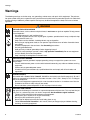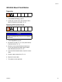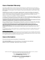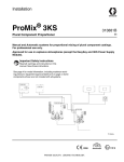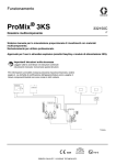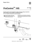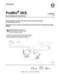
1
Repair-Parts
ProMix® 3KS
313883A
ENG
Plural Component Proportioner
Manual and Automatic systems for proportional mixing of plural component coatings.
For professional use only.
Approved for use in explosive atmospheres (except the EasyKey and 3KS Power Supply
Module).
Important Safety Instructions
Read all warnings and instructions in this
manual. Save these instructions.
See page 4 for model information, including maximum working
pressure. Equipment approval labels are on page 3. Some
components shown are not included with all systems.
TI14543a
0359
#
53
II 2 G
Contents
Related Manuals . . . . . . . . . . . . . . . . . . . . . . . . . . . 3
Equipment Approvals . . . . . . . . . . . . . . . . . . . . . . . 3
System Configuration and Part Numbers . . . . . . . 4
Configurator Key . . . . . . . . . . . . . . . . . . . . . . . . . 4
Warnings . . . . . . . . . . . . . . . . . . . . . . . . . . . . . . . . . 6
Grounding . . . . . . . . . . . . . . . . . . . . . . . . . . . . . . . . 8
Check Resistance . . . . . . . . . . . . . . . . . . . . . . . . . . 8
Pressure Relief Procedure . . . . . . . . . . . . . . . . . . . 8
Troubleshooting . . . . . . . . . . . . . . . . . . . . . . . . . . . 12
Alarm Codes . . . . . . . . . . . . . . . . . . . . . . . . . . . 12
Solenoid Troubleshooting . . . . . . . . . . . . . . . . . 13
3KS Fluid Station CAN Isolation Board
Diagnostics . . . . . . . . . . . . . . . . . . . . . . . . . 16
Color Change Board Diagnostics . . . . . . . . . . . 18
Power Supply Module Barrier Board
Diagnostics . . . . . . . . . . . . . . . . . . . . . . . . . 20
Fluid Manifold Troubleshooting . . . . . . . . . . . . . 21
Schematic Diagrams . . . . . . . . . . . . . . . . . . . . . . . 22
System Pneumatic Schematic
(2KS Fluid Panel) . . . . . . . . . . . . . . . . . . . . 22
System Electrical Schematic . . . . . . . . . . . . . . . 24
Power Supply Module Electrical Schematic . . . 28
Tubing Schematic . . . . . . . . . . . . . . . . . . . . . . . 29
2
Service . . . . . . . . . . . . . . . . . . . . . . . . . . . . . . . . . . 30
Before Servicing . . . . . . . . . . . . . . . . . . . . . . . . 30
After Servicing . . . . . . . . . . . . . . . . . . . . . . . . . . 30
Servicing Power Supply Module . . . . . . . . . . . . 31
3KS Wall Mount Fluid Station . . . . . . . . . . . . . . 35
Servicing Flow Meters . . . . . . . . . . . . . . . . . . . . 39
Servicing Fluid Manifold . . . . . . . . . . . . . . . . . . 40
Servicing Color Change Module, Color/Catalyst
Valves, and Dump Valves . . . . . . . . . . . . . . 40
Parts . . . . . . . . . . . . . . . . . . . . . . . . . . . . . . . . . . . . 41
Configurator Key . . . . . . . . . . . . . . . . . . . . . . . . 41
ProMix 3KS System . . . . . . . . . . . . . . . . . . . . . . 42
Color Change Accessory Kits . . . . . . . . . . . . . . 43
258670 Power Supply Module . . . . . . . . . . . . . . 44
Wall Mount Fluid Station . . . . . . . . . . . . . . . . . . 46
Available Cables . . . . . . . . . . . . . . . . . . . . . . . . 48
Technical Data . . . . . . . . . . . . . . . . . . . . . . . . . . . . 49
Graco Standard Warranty . . . . . . . . . . . . . . . . . . . 50
Graco Information . . . . . . . . . . . . . . . . . . . . . . . . . 50
313883A
Related Manuals
Related Manuals
Equipment Approvals
Component Manuals in English
Equipment approvals appear on the following labels
which are attached to the Fluid Station and Power Supply Module. See FIG. 1 on page 4 for label locations.
Manual
Description
313881
313882
313885
312775
312776
312777
312778
312779
312780
ProMix 3KS Kit Installation
ProMix 3KS Manual System Operation
ProMix 3KS Automatic System Operation
ProMix 2KS Manual System Installation
ProMix 2KS Manual System Operation
ProMix 2KS Manual System Repair-Parts
ProMix 2KS Automatic System Installation
ProMix 2KS Automatic System Operation
ProMix 2KS Automatic System
Repair-Parts
Fluid Mix Manifold
Dispense Valve
Color Change Valve Stacks
Color Change Module Kit
Gun Flush Box Kits
Gun Air Shutoff Kit
Dump Valve and Third Purge Valve Kits
Network Communication Kits
G3000/G3000HR Flow Meter
Coriolis Flow Meter
Floor Stand Kit
Beacon Kit
Basic Web Interface/Advanced Web
Interface
15V256 Automatic System Upgrade Kit
15V825 Discrete I/O Board Kit
312781
312782
312783
312787
312784
310745
312786
312785
308778
313599
313290
313542
313386
406799
406800
Power Supply Module and Fluid Station Label
ATEX Certificate is listed here
®
ProMix 3KS
Electronic Proportioner
C
FM08ATEX0074
II 2 G
Ex ia IIA T3
US
Intrinsically safe
equipment for Class I,
Div 1, Group D, T3
Ta = -20°C to 50°C
Intrinsically Safe (IS) System. Install
per IS Control Drawing No. 258682.
EasyKey Interface IS Associated
Apparatus for use in non hazardous
location, with IS Connection to Smart
Fluid Plate IS
Apparatus for use in:
Class I, Division 1, Group D T3 C
Hazardous Locations
Read Instruction Manual
MAX AIR WPR
.7
MPa
7
100
bar
PSI
Warning: Substitution of components
may impair intrinsic safety.
PART NO.
SERIES
SERIAL
MAX FLUID WPR
MFG. YR.
MPa
bar
GRACO INC.
P.O. Box 1441
Minneapolis, MN
55440 U.S.A.
PSI
MAX TEMP 50°C (122°F)
TI14376a
Fluid Station Label
ProMix® 3KS
PART NO.
C
SERIES
FLUID PANEL
MAX AIR WPR
SERIAL MFG. YR.
Intrinsically safe equipment
for Class I, Div 1, Group D, T3
US Ta = -20°C to 50°C
Install per 289833
.7
7
MPa
bar
100
PSI
GRACO INC.
P.O. Box 1441
Minneapolis, MN
55440 U.S.A.
FM08ATEX0073
II 2 G
Ex ia IIA T3
TI14374a
ATEX Certificate is listed here
Power Supply Module Label
POWER REQUIREMENTS
ProMix® 3KS
PART NO. SERIES NO. MFG. YR.
VOLTS
85-250 ~
AMPS 2 AMPS MAX
GRACO INC.
C
P.O. Box 1441
Minneapolis, MN
55440 U.S.A.
50/60 Hz
Intrinsically safe connections
for Class I, Div 1, Group D
US Ta = -20°C to 50°C
Install per 258682
II (2) G
[Ex ia] IIA
FM08ATEX0072
Um: 250 V
TI14375a
ATEX Certificate is listed here
313883A
3
System Configuration and Part Numbers
System Configuration and Part Numbers
Configurator Key
The configured part number for your equipment is printed on the equipment identification
labels. See FIG. 1 for location of the identification labels. The part number includes digits from
each of the following categories, depending on the configuration of your system.
3K
System
Component C
Fluid Meter
Component C Change
TK
0 = No Meter
0 = No Valves (single component C)
1 = G3000
1 = Two Valves (low pressure)
2 = G3000HR
2 = Four Valves (low pressure)
3 = 1/8 in. Coriolis
3= Two Valves (high pressure)
4 = Solvent Meter
4= Four Valves (high pressure)
®
ProMix 3KS
Electronic Proportioner
C
Label Location
on Fluid Station
FM08ATEX0074
II 2 G
Ex ia IIA T3
Not
Designated
0
0
Intrinsically Safe (IS) System. Install
per IS Control Drawing No. 258682.
EasyKey Interface IS Associated
Apparatus for use in non hazardous
location, with IS Connection to Smart
Fluid Plate IS
Apparatus for use in:
Class I, Division 1, Group D T3 C
Hazardous Locations
Label Location on
Power Supply Module
Read Instruction Manual
TI14361a
Maximum Fluid
Working Pressure
is listed here
US
Intrinsically safe
equipment for Class I,
Div 1, Group D, T3
Ta = -20°C to 50°C
Not
Designated
MAX AIR WPR
.7
7
100
MPa
bar
PSI
PART NO.
SERIES
SERIAL
MAX FLUID WPR
MFG. YR.
MPa
bar
PSI
MAX TEMP 50°C (122°F)
TI14370a
Warning: Substitution of components
may impair intrinsic safety.
GRACO INC.
P.O. Box 1441
Minneapolis, MN
55440 U.S.A.
Configured Part Number
TI14376a
FIG. 1: Identification Label
4
313883A
System Configuration and Part Numbers
Hazardous Location Approval
Models using a G3000, G3000HR, or intrinsically safe Coriolis meter for A, B, and C meters are approved for
installation in a Hazardous Location - Class I, Div I, Group D, T3 or Zone I Group IIA T3.
Maximum Working Pressure
Maximum working pressure rating is dependent on the fluid component options selected. The pressure rating is
based on the rating of the lowest rated fluid component. Refer to the component pressure ratings below.
Example: A Model with Flow Control has a maximum working pressure of 190 psi (1.31 MPa, 13.1 bar).
Check the identification label on the EasyKey, power supply module, or fluid station for the system maximum working pressure. See FIG. 1.
ProMix Fluid Manifold Components Maximum Working Pressure
Base System (no meters [option 0], no color/component C change [option 0],
and no flow control [Optional with ProMix 2KS Base Unit]) . . . . . . . . . . . . . . . . . . . .3000 psi (21.0 MPa, 210 bar)
Meter Option 1, 2, and 4 (G3000, G3000HR, or Solvent Meter) . . . . . . . . . . . . . . . .3000 psi (21.0 MPa, 210 bar)
Meter Option 3 (Coriolis Meter) . . . . . . . . . . . . . . . . . . . . . . . . . . . . . . . . . . . . . . 2300 psi (15.86 MPa, 158.6 bar)
Color Change Option 1 and 2 (low pressure valves) . . . . . . . . . . . . . . . . . . . . . . . . . 300 psi (2.07 MPa, 20.6 bar)
Color Change Option 3 and 4 (high pressure valves). . . . . . . . . . . . . . . . . . . . . . . . . . 3000 psi (21 MPa, 210 bar)
Flow Control (Optional with ProMix 2KS Automatic System Base Unit) . . . . . . . . . . . 190 psi (1.31 MPa, 13.1 bar)
Flow Meter Fluid Flow Rate Range
G3000 . . . . . . . . . . . . . . . . . . . . . . . . . . . . . . . . . . . . . . . . . . . . . . . . . . . . . . . 75-3800 cc/min. (0.02-1.0 gal./min.)
G3000HR . . . . . . . . . . . . . . . . . . . . . . . . . . . . . . . . . . . . . . . . . . . . . . . . . . . 38-1900 cc/min. (0.01-0.50 gal./min.)
Coriolis Meter . . . . . . . . . . . . . . . . . . . . . . . . . . . . . . . . . . . . . . . . . . . . . . 20-3800 cc/min. (0.005-1.00 gal./min.)
S3000 Solvent Meter (accessory) . . . . . . . . . . . . . . . . . . . . . . . . . . . . . . . . 38-1900 cc/min. (0.01-0.50 gal./min.)
313883A
5
Warnings
Warnings
The following warnings are for the setup, use, grounding, maintenance, and repair of this equipment. The exclamation point symbol alerts you to a general warning and the hazard symbol refers to procedure-specific risk. Refer back
to these warnings. Additional, product-specific warnings may be found throughout the body of this manual where
applicable.
WARNING
FIRE AND EXPLOSION HAZARD
Flammable fumes, such as solvent and paint fumes, in work area can ignite or explode. To help prevent
fire and explosion:
• Use equipment only in well ventilated area.
• Eliminate all ignition sources; such as pilot lights, cigarettes, portable electric lamps, and plastic drop
cloths (potential static arc).
• Keep work area free of debris, including solvent, rags and gasoline.
• Do not plug or unplug power cords, or turn power or light switches on or off when flammable fumes
are present.
• Ground all equipment in the work area. See Grounding instructions.
• Use only grounded hoses.
• Hold gun firmly to side of grounded pail when triggering into pail.
• If there is static sparking or you feel a shock, stop operation immediately. Do not use equipment
until you identify and correct the problem.
• Keep a working fire extinguisher in the work area.
ELECTRIC SHOCK HAZARD
This equipment must be grounded. Improper grounding, setup, or usage of the system can cause
electric shock.
• Turn off and disconnect power at main switch before disconnecting any cables and before servicing
equipment.
• Connect only to grounded power source.
• All electrical wiring must be done by a qualified electrician and comply with all local codes and
regulations.
INTRINSIC SAFETY
Only models with a G3000, G250, G3000HR, G250HR, or intrinsically safe Coriolis meter for A, B, and C
meters are approved for installation in a Hazardous Location - Class I, Div I, Group D, T2 C. To help prevent fire and explosion:
• Do not install equipment approved only for a non-hazardous location in a hazardous area. See the
ID label for the intrinsic safety rating of your model.
• Do not substitute system components as this may impair intrinsic safety.
SKIN INJECTION HAZARD
High-pressure fluid from gun, hose leaks, or ruptured components will pierce skin. This may look like just
a cut, but it is a serious injury that can result in amputation. Get immediate surgical treatment.
• Tighten all fluid connections before operating the equipment.
• Do not point gun at anyone or at any part of the body.
• Do not put your hand over the spray tip.
• Do not stop or deflect leaks with your hand, body, glove, or rag.
• Follow Pressure Relief Procedure in this manual, when you stop spraying and before cleaning,
checking, or servicing equipment.
6
313883A
Warnings
WARNING
EQUIPMENT MISUSE HAZARD
Misuse can cause death or serious injury.
• Do not operate the unit when fatigued or under the influence of drugs or alcohol.
• Do not exceed the maximum working pressure or temperature rating of the lowest rated system
component. See Technical Data in all equipment manuals.
• Use fluids and solvents that are compatible with equipment wetted parts. See Technical Data in all
equipment manuals. Read fluid and solvent manufacturer’s warnings. For complete information
about your material, request MSDS forms from distributor or retailer.
• Check equipment daily. Repair or replace worn or damaged parts immediately with genuine manufacturer’s replacement parts only.
• Do not alter or modify equipment.
• Use equipment only for its intended purpose. Call your distributor for information.
• Route hoses and cables away from traffic areas, sharp edges, moving parts, and hot surfaces.
• Do not kink or over bend hoses or use hoses to pull equipment.
• Keep children and animals away from work area.
• Comply with all applicable safety regulations.
MOVING PARTS HAZARD
Moving parts can pinch or amputate fingers and other body parts.
• Keep clear of moving parts.
• Do not operate equipment with protective guards or covers removed.
• Pressurized equipment can start without warning. Before checking, moving, or servicing equipment,
follow the Pressure Relief Procedure in this manual. Disconnect power or air supply.
TOXIC FLUID OR FUMES HAZARD
Toxic fluids or fumes can cause serious injury or death if splashed in the eyes or on skin, inhaled, or
swallowed.
• Read MSDS’s to know the specific hazards of the fluids you are using.
• Store hazardous fluid in approved containers, and dispose of it according to applicable guidelines.
• Always wear impervious gloves when spraying or cleaning equipment.
PERSONAL PROTECTIVE EQUIPMENT
You must wear appropriate protective equipment when operating, servicing, or when in the operating
area of the equipment to help protect you from serious injury, including eye injury, inhalation of toxic
fumes, burns, and hearing loss. This equipment includes but is not limited to:
• Protective eyewear
• Clothing and respirator as recommended by the fluid and solvent manufacturer
• Gloves
• Hearing protection
313883A
7
Grounding
Grounding
Your system must be grounded. See the Grounding
instructions in your ProMix 3KS Installation manual.
Pressure Relief
Procedure
NOTE: The following procedures relieve all fluid and air
pressure in the ProMix 3KS system. Use the procedure
appropriate for your system configuration.
Check Resistance
Relieve pressure when you stop spraying, before
changing spray tips, and before cleaning, checking, or
servicing equipment.
To ensure proper grounding, resistance between ProMix components and true earth ground must be less
than 1 ohm. Read Warnings, page 6.
Have a qualified electrician check resistance between
each ProMix component and true earth ground. If resistance is greater than 1 ohm, a different ground site may
be required. Do not operate the system until the problem
is corrected.
Single Color Systems
1. While in Mix mode (gun triggered), shut off the A, B,
and C fluid supply pumps/pressure pots. Close all
fluid shutoff valves at the pump outlets.
2. With the gun triggered, push the manual override on
the A, B, and C dose valve solenoids to relieve pressure. See FIG. 4.
NOTE: If a Dose Time alarm (E-7, E-8) occurs, clear
the alarm.
3. Do a complete system purge, following the instructions under Purging Using Recipe 0 in your system
Operation manual.
4. Shut off the fluid supply to the solvent purge valve
(SPV) and the air supply to the air purge valve
(APV), FIG. 3.
5. With the gun triggered, push the manual override on
the A, B, and C purge valve solenoids to relieve air
and solvent pressure. See FIG. 4. Verify that solvent
pressure is reduced to 0.
NOTE: If a Purge Volume alarm (E-11) occurs, clear
the alarm.
8
313883A
Pressure Relief Procedure
Systems with Color Change and without
Dump Valves
NOTE: This procedure relieves pressure through the
sampling valve.
1. Complete all steps under Single Color Systems,
page 8.
2. Close the A side shutoff valve (SVA), FIG. 3. Open
the A side sampling valve (RVA).
3. Direct the A side sampling tube into a waste container.
4. See FIG. 2. Open the color change module. Using
the solenoid identification labels as a guide, press
and hold the override button on each color solenoid
until flow from the sampling valve stops.
5. Press and hold the solvent solenoid override until
clean solvent comes from the sampling valve, then
release.
6. See FIG. 2. Using the solenoid identification labels
as a guide, press and hold the override button on
each catalyst solenoid until flow from dump valve B
stops.
7. Press and hold the dump valve C solenoid override,
FIG. 5.
8. See FIG. 2. Open the color change module. Using
the solenoid identification labels as a guide, press
and hold the override button on each color solenoid
until flow from dump valve C stops.
9. Press and hold the dump valve A solenoid override,
FIG. 4.
10. Press and hold the A side (color) solvent solenoid
override until clean solvent comes from the dump
valve, then release.
11. Press and hold the dump valve B solenoid override,
FIG. 4.
6. Shutoff the solvent supply to the color change stack
solvent valve.
12. Press and hold the B side (catalyst) solvent solenoid
override until clean solvent comes from the dump
valve, then release.
7. Press and hold the solvent solenoid override until
solvent flow from the sampling valve stops.
13. Press and hold the dump valve C solenoid override,
FIG. 5.
8. Open the A side shutoff valve (SVA), FIG. 3. Close
the A side sampling valve (RVA).
14. Press and hold the C side solvent solenoid override
until clean solvent comes from the dump valve, then
release.
Systems with Color/Catalyst/Component C
Change and Dump Valves
NOTE: This procedure relieves pressure through the
dump valves.
1. Complete all steps under Single Color Systems,
page 8.
15. Shutoff the solvent supply to the color/catalyst/component C change stack solvent valves.
16. Press and hold the A, B, and C solvent solenoid
overrides and dump valve overrides until solvent
flow from the dump valves stops.
2. Shut off all color/catalyst/component C supplies to
the valve stacks.
3. Press and hold the dump valve A solenoid override,
FIG. 4.
4. See FIG. 2. Open the color change module. Using
the solenoid identification labels as a guide, press
and hold the override button on each color solenoid
until flow from dump valve A stops.
5. Press and hold the dump valve B solenoid override,
FIG. 4.
313883A
9
Pressure Relief Procedure
Module #1
Solenoid
Identification
Label
Catalyst
Color
Color
Solenoid
Identification
Label
TI12826a
Solvent Solenoid
Overrides
Module #2
Catalyst
Color
Color
Solenoid
Identification
Label
Solvent Solenoid
Overrides
Solenoid
Identification
Label
Mount Component C
Valves Here
TI12826a
FIG. 2: Color Change Solenoids
10
313883A
Pressure Relief Procedure
DVA
FI
DVB
MB
MS
MA
RVB
RVA
TI12556a
APV
AT
SVA
SM
SVB
SPV
Key: ProMix 2KS Fluid Station
FI
MA Component A Meter
DVA Component A Dose Valve
RVA Component A Sampling
Valve
SVA Component A Shutoff
Valve
MB Component B Meter
DVB Component B Dose Valve
RVB Component B Sampling
Valve
DVC
SVB Component B Shutoff
Valve
MS Solvent Meter
SPV Solvent Purge Valve
APV Air Purge Valve
SM Static Mixer
FI
Fluid Integrator
AT
Air Purge Valve Air Supply
Tube
Key: ProMix 3KS Fluid Station
MC
CPV
RVC
1
MC
DVC
RVC
SVC
CPV
SM
FI
Component C Meter
Component C Dose Valve
Component C Sampling Valve
Component C Shutoff Valve
Component C Purge Valve
Static Mixer
Fluid Integrator
1
3KS fluid inlet. Connect fluid supply line from
2KS fluid manifold outlet here.
2
Connect fluid supply line to gun.
SVC
SM
2
TI14382a
FIG. 3. ProMix 2KS and ProMix 3KS Wall Mount Fluid Stations
313883A
11
Troubleshooting
Troubleshooting
Table 1: System Alarm Codes
Code Description
Follow Pressure Relief Procedure, page 8, before
cleaning, checking, or servicing equipment.
NOTICE
Do not use the fluid in the line that was dispensed off
ratio as it may not cure properly.
NOTE: For complete system troubleshooting, including
the EasyKey, A/B Fluid Station, Booth Control, and
Optional Flow Control, see your ProMix 2KS
Repair-Parts Manual.
Alarm Codes
Table 1 lists the system alarm codes. See the system
operation manual for complete information on alarm
troubleshooting.
12
E-1
Communication Error Alarm
E-2
Potlife Alarm
E-3
Ratio High Alarm
E-4
Ratio Low Alarm
E-5
Overdose A/B Dose Too Short Alarm
E-6
Overdose B/A Dose Too Short Alarm
E-7
Dose Time A Alarm
E-8
Dose Time B Alarm
E-9
Mix in Setup Alarm
E-10
Remote Stop Alarm
E-11
Purge Volume Alarm
E-12
CAN Network Communication Error Alarm
E-13
High Flow Alarm
E-14
Low Flow Alarm
E-15
System Idle Warning
E-16
Setup Change Warning
E-17
Power On Warning
E-18
Defaults Loaded Warning
E-20
Purge Initiate Alarm
E-21
Material Fill Alarm
E-22
Tank A Low Alarm
E-23
Tank B Low Alarm
E-24
Tank S Low Alarm
E-25
Auto Dump Complete Alarm
E-26
Color/Catalyst Purge Alarm
E-27
Color/Catalyst Fill Alarm
E-29
Tank C Low Alarm
E-30
Overdose C Alarm
E-31
Dose Time C Alarm
313883A
Troubleshooting
Solenoid Troubleshooting
NOTE: Refer to the Schematic Diagrams, page 22.
1
AFS #1
AFS #2
SOLV SW
Power
J1
Fiber
Optic
GFB 1 PS
GFB 2 PS
CAN
J13
Dose B
Dose C
J9
1
+ + +
J14
1
+ + +
J15
1
+ +
Dump B
Dump C
Air
Dose A
Valve Overrides
J3
GFB 1
Flow B
GFB 2
Flow A
CAN
J12
3rd Flush
Flow C
Purge C
Dump A
+ 1
G
s
+
G
s
+ 1
G
s
+
G
s
+ 1
+
+
Flow Solv
Solvent
Not Used
+
J8
Dump Valve A
Dump Valve B
GFB 1
Optional Solenoid
Locations
GFB 2
3rd Purge Valve
Solenoid
Dose Valve A
Solenoid
Dose Valve B
Solenoid
Purge Valve A
Solenoid
Purge Valve B
Solenoid
TI12652a
FIG. 4: ProMix 2KS Fluid Station Board and Component A and B Solenoids
313883A
13
Troubleshooting
J8
(Communication)
Valve
Overrides
J3
(Power Input)
VDC
J2
(Color Change
Module)
J1
(Booth Control)
Dose Valve C
Solenoid
Purge Valve C
Solenoid
Dump Valve C
location (optional)
TI14704a
FIG. 5. ProMix 3KS Fluid Station CAN Isolation Board and Component C Solenoids
14
313883A
Troubleshooting
See FIG. 4 and FIG. 5 to troubleshoot the 2KS and 3KS solenoids. Also see the System Electrical Schematic on
pages 24 and 26.
If the dispense or purge valves are not turning on or off correctly, it could be caused by one of the following.
Table 2: Solenoid Troubleshooting
Cause
1. Air regulator pressure set too
high or too low.
Solution
Check air pressure. 80-90 psi (550-630 kPa, 5.5-6.3 bar) is commonly used.
Do not go below 75 psi (0.5 MPa, 5.2 bar) or above 120 psi (0.8 MPa, 8 bar),
2. Air or electrical lines damaged or Visually inspect air and electrical lines for kinks, damage, or loose connecconnections loose.
tions. Service as needed.
3. Solenoid failure.
Check the applicable solenoid’s LED (see FIG. 7 and Table 4). If lit, proceed
with the following checks. If not lit, go to Cause 4.
Remove the connector for the applicable solenoid and measure voltage
across the pins on the board. If voltage is between 9-15 Vdc, replace the
solenoid.
Manually operate the valves by removing the color change module cover and
pressing and releasing solenoid valve override buttons. FIG. 2.
Valves should snap open and shut quickly. If the valves actuate slowly, it
could be caused by:
• Air pressure to the valve actuators is too low. See Cause 1.
• Solenoid is clogged. Make sure air supply has 10 micron filter installed.
• Something is restricting the solenoid or tubing. Check for air output from
air line for corresponding solenoid when valve is actuated. Clear restriction.
• A dose valve is turned in too far. See ProMix 3KS Operation manual for
settings,
• Fluid pressure is high and air pressure is low.
4. Fluid station control board or
cable failure.
If there is no voltage across the pins on the board or it is less than 9 Vdc,
check LEDs D9 and D10 (see FIG. 7 and Table 4). If both are lit and functioning properly, or other solenoids in the module are working properly, replace
the color change board.
If D9 and D10 are not lit:
•
•
313883A
Check if the cable is disconnected or damaged.
Check the fluid station control board (see the ProMix 2KS Repair-Parts
Manual).
15
Troubleshooting
3KS Fluid Station CAN Isolation Board Diagnostics
See FIG. 6 and Table 3 to troubleshoot the 3KS fluid station CAN isolation board. Also see the System Electrical
Schematic on pages 24 and 26.
J8
(Power Input from
2KS Fluid Station)
VDC
J3
(Power Input
from 3KS Power
Supply Module)
D6
J2
(Color Change
Module)
S1
ON
ON
OFF
OFF
D7
J1
(Booth Control)
TI13661a
D8
TI14373a
FIG. 6: 258673 3KS Fluid Station CAN Isolation Board
16
313883A
Troubleshooting
Table 3: 3KS Fluid Station CAN Isolation Board Diagnostics
Component
Connector
Signal Description
Diagnosis
D7 (green LED) J8
Input Power from 2KS
Fluid Station
On (steady green) when power is supplied to CAN
isolation board.
D8 (green LED) J3
Input Power from 3KS
Power Supply Module
On (steady green) when power is supplied to CAN
isolation board.
D6 (green LED) n/a
Communication (green)
Blinks rapidly during normal operation.
On (steady green) or not lit, there is a communication
fault.
S1
J1, J2
n/a
If booth control is connected to J1 and color change
module is connected to J2, set switch S1 to OFF.
If booth control is connected to J1 or color change
module is connected to J2, set switch S1 to ON.
If booth control is not connected to J1 and color
change module is not connected to J2, set switch S1
to ON.
313883A
17
Troubleshooting
Color Change Board Diagnostics
See FIG. 7 and Table 4 to troubleshoot the color change board. Also see the System Electrical Schematic on pages
24 and 26.
J8, Pin 1
D33
D34
D43
D31
D44
D29
J9, Pin 1
J15, Pin 1
D39
D41
D32
D35
D38
J16, Pin 1
D27
D37
J14, Pin 1
D45
D30
D46
D28
J10, Pin 1
D36
D9
D10
D8
F1 (Fuse)
J7
J11
FIG. 7: 256172 Color Change Board
18
313883A
Troubleshooting
Table 4: Color Change Board Diagnostics
LED
Connector
and Pin Nos.
Board 1 Signal
Description
Board 2 Signal
Description
D8
n/a
Board OK
Board OK
Blinks (heartbeat) during normal
operation.
D9
n/a
Communication (yellow)
Communication (yellow)
Turns on when board is communicating with ProMix 3KS.
D10
J7
Power
Power
Turns on when power is supplied
to the board.
D27
J15, 5 & 6
Color 3
Color 16
D28
J14, 3 & 4
Color 1
Color 14
D29
J8, 5 & 6
Color 6
Color 19
D30
J14, 1 & 2
Color 2
Color 15
D31
J8, 3 & 4
Color 7
Color 20
D32
J16, 3 & 4
Catalyst 4
Component C 4
D33
J8, 1 & 2
Color 8
Color 21
D34
J9, 5 & 6
Color 9
Color 22
D35
J15, 3 & 4
Color 4
Color 17
D36
J14, 5 & 6
Solvent (Color)
Color 13
D37
J10, 5 & 6
Catalyst 2
Component C 2
D38
J16, 1 & 2
Catalyst 3
Component C 3
D39
J16, 5 & 6
Color 12
Color 25
D41
J15, 1 & 2
Color 5
Color 18
D43
J9, 3 & 4
Color 10
Color 23
D44
J9, 1 & 2
Color 11
Color 24
D45
J10, 3 & 4
Catalyst 1
Component C 1
D46
J10, 1 & 2
Solvent (Catalyst)
Solvent (Component C)
F1
Replaceable
Fuse
n/a
n/a
313883A
Diagnosis
D27 through D46 turn on when
ProMix 3KS sends a signal to
actuate the related solenoid
valve.
Check fuse condition if there is
no power to the board or if communication is interrupted
between the fluid station and the
color change module.
19
Troubleshooting
Power Supply Module Barrier Board Diagnostics
See FIG. 8 and Table 5 to troubleshoot the Power Supply Module barrier board. Also see the Power Supply Module
Electrical Schematic on page 28 and the System Electrical Schematic on pages 24 and 26.
J4, Pin 1
J1, Pin 1
D5
F1
F2
F4
F3
D4
J5, Pin 1
FIG. 8: 255786 Power Supply Module Barrier Board
Table 5: Power Supply Module Barrier Board Diagnostics
Connector Description
Diagnosis
J1
AC Power Input
n/a
J4
24 Vdc Power Input to
EasyKey Display Board
D5 turns on.
J5
12 Vdc Power Output to
Fluid Station Board
D4 turns on if barrier board is functioning. If D4 does not turn on, fuses F3
or F4 (Graco Part No. 15D979) are blown or there is no input power at J4.
If there is no input power (D5 does not light), fuses F1 and F2 (Graco Part
No. 114788) may be blown.
20
313883A
Troubleshooting
Fluid Manifold Troubleshooting
See FIG. 9. To remove the fluid manifold, see page 40. See manual 312581 for complete information on the fluid manifold.
FI
CCV
DVC OFF
DVC
DVC ON
CSL
MC
SPV OFF
ABS
SPV ON
SVC
RVC
SM
SPV
TI14382a
Key:
ABS
MC
DVC
RVC
SVC
A + B Fluid Inlet (from 2KS Panel)
Component C Meter
Component C Dose Valve
Component C Sampling Valve
Component C Shutoff Valve
CSL
CCV
SPV
SM
FI
Component C Supply Line
Meter C Check Valve
Solvent Purge Valve
3KS Static Mixer
3KS Fluid Integrator
FIG. 9. Fluid Manifold
313883A
21
Schematic Diagrams
Schematic Diagrams
System Pneumatic Schematic (2KS Fluid Panel)
COLOR
CHANGE
CONTROL
COLOR
VALVE
STACKS
AIR EXHAUST MUFFLER
COLOR 1
COLOR 2
12 VDC
COLOR 3
E
UB
2T
5/3 N
E
OP
A B
12 VDC
4-WAY SOLENOID
SE
O
CL
E
B
TU
DOSE B
VALVE
2
5/3 N
E
OP
A B
12 VDC
E
4-WAY SOLENOID
OS
05
CL
3/8 AIR FILTER
MANUAL DRAIN
5 MICRON
WALL MOUNT ONLY
CONTROL AIR
A B
COLOR 4
DOSE A
VALVE
COLOR 5
COLOR 6
1/4 TUBE
1/4 TUBE
TO MANIFOLD
O
CL
E
B
TU
2
5/3 N
E
OP
PURGE A
VALVE
COLOR 7
COLOR 8
COLOR SOLVENT
FLUSH AIR TO FLUID INLET
SE
4-WAY SOLENOID
COLOR 9
COLOR 10
COLOR 11
COLOR 12
CATALYST 1
CATALYST 2
CATALYST 3
CATALYST 4
CATALYST SOLVENT
12 VDC
OS
E
E
UB
2T
3
/
5
N
E
OP
PURGE B
VALVE
E
E
UB
2T
3
5/ N
E
OP
PURGE C
VALVE
(OPTIONAL)
4-WAY SOLENOID
CL
A B
AIR INPUT
MAC
36 SERIES SOLENOID VALVES
12 VDC
OS
4-WAY SOLENOID
CL
A B
PURGE AIR
AIR EXHAUST MUFFLER
12 VDC
3-WAY SOLENOID
E
DUMP A
VALVE
(OPTIONAL)
E
DUMP B
VALVE
(OPTIONAL)
A
UB
2T
5/3 N
E
OP
A
UB
2T
5/3 N
E
P
O
A
E
UB
2T
5/3 N
E
P
O
A
UB
2T
5/3 N
E
P
O
AIR INPUT
12 VDC
3-WAY SOLENOID
12 VDC
3-WAY SOLENOID
GFB 1
VALVE
(OPTIONAL)
12 VDC
3-WAY SOLENOID
E
GFB 2
VALVE
(OPTIONAL)
MANIFOLD
22
313883A
Schematic Diagrams
System Pneumatic Schematic (3KS Fluid Panel)
COLOR
CHANGE
CONTROL
COLOR
VALVE
STACKS
3RD COMP. 1
3RD COMP. 2
3RD COMP. 3
3RD COMP. 4
1/4 TUBE
3RD COMP. SOLVENT
COLOR 13 (OPTIONAL)
COLOR 14 (OPTIONAL)
COLOR 15 (OPTIONAL)
TO MANIFOLD
COLOR 16 (OPTIONAL)
COLOR 17 (OPTIONAL)
COLOR 18 (OPTIONAL)
COLOR 19 (OPTIONAL)
COLOR 20 (OPTIONAL)
COLOR 21 (OPTIONAL)
COLOR 22 (OPTIONAL)
AIR EXHAUST MUFFLER
COLOR 23 (OPTIONAL)
COLOR 24 (OPTIONAL)
COLOR 25 (OPTIONAL)
12 VDC
E
S
LO
C
4-WAY SOLENOID
A B
E
UB
2T
5/3 N
E
OP
DOSE C
VALVE
MAC
36 SERIES SOLENOID VALVES
12 VDC
E
E
UB
2T
5/3 N
E
OP
OS
CL
4-WAY SOLENOID
A B
PURGE C
VALVE
12 VDC
3-WAY SOLENOID
A
E
UB
2T
5/3 N
E
OP
DUMP C
VALVE
(OPTIONAL)
MANIFOLD
313883A
23
DISPLAY
MEMBRANE
SWITCH
WITH
RIBBON
CABLE
J2
J4
1
2
3
4
5
6
7
8
9
10
11
12
13
14
15
16
17
18
19
20
1
2
3
4
5
6
7
8
9
10
11
DISPLAY
BOARD
P1
J6
RJ45
1
2
3
4
RJ45
J7
J8
J10
RJ45
1
2
3
4
5
6
1
2
3
4
J5 5
6
7
8
9
10
RJ45
J9
POWER HARNESS
BARRIER
BOARD
POWER
SUPPLY
+
+
+
+
-
POWER DIST.
TERMINAL
BLOCKS
+
+
-
3'
1
2
3
1
2
3
J4
1
2
3
4
5
1
2
J5
J1
WEB SERVER
MODULE
3'
(25'-200' OPTIONS)
RJ45
BULKHEAD
RS485 INTEGRATION A (WHT/BLU)
RS485 INTEGRATION B (BLU/WHT)
RS485 INTEGRATION GROUND (SHIELD)
RS485 NETWORK A (WHT/ORG)
RS485 NETWORK B (ORG/WHT)
RS485 NETWORK GROUND (SHIELD)
I/O HARNESSES
FLOW CONTROL CAL. (BLK)
GUN TRIGGER (WHT)
DIGITAL IN COMMON (RED)
REMOTE STOP (GRN)
ALARM RESET (BRN)
ALARM OUTPUT (BLU)
DIGITAL OUTPUT COMMON (ORG)
POT LIFE (YEL)
FLOW RATE ANALOG IN (PUR)
FLOW RATE ANALOG COMMON (GRAY)
FO IN (BLK)
FO OUT (BLU)
+
-
DC OK
+24 VDC
COMMON
COMMON
RJ45
RJ45
24
+24VDC
OPEN
COMMON
UNUSED
UNUSED
UNUSED
UNUSED
UNUSED
HARNESS
+
-
3'
1
2
3
4
5
6
1
2
3
4
5
6
7
8
9
10
1
2
3
J3
GND LUG
LINE
FILTER
L1
N
GND
5
6
(+24) YEL
(COM) GRAY
ORG
BRN
RED
BEACON
DIGITAL OUTPUT COMMON/POWER
SPECIAL OUTPUT #1
SPECIAL OUTPUT #2
SPECIAL OUTPUT #3
SPECIAL OUTPUT #4
DIGITAL OUTPUT COMMON/POWER
J5 4
1
2
3
DIGITAL OUTPUT COMMON/POWER
PURGE/RECIPE CHG ACTIVE OUTPUT
MIX ACTIVE OUTPUT
MIX READY OUTPUT
FILL ACTIVE
FLOW CAL. ACTIVE
FLOW RATE ALARM OUTPUT
DIGITAL OUTPUT COMMON/POWER
MIX INPUT
PURGE INPUT
JOB COMPLETE INPUT
EXTERNAL CLR CHG READY
RESET ALARM INPUT
DIGITAL INPUT COMMON
DIGITAL INPUT COMMON
RECIPE BIT 0 INPUT
RECIPE BIT 1 INPUT
RECIPE BIT 2 INPUT
RECIPE BIT 3 INPUT
RECIPE BIT 4 INPUT
RECIPE BIT 5 INPUT
RECIPE CHANGE INPUT
1 POWER
2 ROCKER
1A SWITCH
1B
2A
2B
1
2
3
L1
N
1
2
3
4
J4 5
6
7
8
5
6
1
2
3
4
5
6
7
8
J2 4
OPEN
OPEN
REMOTE
I/O
INTEGRATION
BOARD
RJ45
TERMINAL
BLOCKS
RJ45
ALARM
+12VDC I/S (RED)
COM (BLACK)
SHIELD
L1 85-250 VAC
N
SHIELD
PROMIX 2KS EASYKEY INTERFACE
CABLE
L1 TERMINAL
N
BLOCK
GND
L1
N
GND
L1
85-250
N
VAC
GND
Schematic Diagrams
System Electrical Schematic
NOTE: The electrical schematic illustrates all possible wiring expansions in a ProMix 3KS system. Some components shown are not included with all systems.
Non-Hazardous Area
313883A
313883A
POWER
HARNESS
POWER
HARNESS
DC OK
+24 VDC
DC OK
COMMON
+24 VDC
COMMON
COMMON
COMMON
+
+
+ + -
BARRIER
BOARD
BARRIER
BOARD
POWER
SUPPLY
POWER
SUPPLY
J5
1
2
3
1
2
13
24
35
4
5
1
2
J5
1
2
31
J4 2
3
1
J4 2
3
J1
J1
1
2
+12VDC
I/S (RED)
HARNESS
COM (BLACK)
SHIELD
+12VDC I/S (RED)
COM (BLACK)
+24VDC SHIELD
OPEN
COMMON
+24VDC
OPEN
COMMON
N
L1
NL1
L1N
L1GND
N
GND HARNESS
L1 85-250 VAC
N
L1 85-250 VAC
N
PROMIX 3KS BARRIER/PS ENCLOSURE
PROMIX 3KS BARRIER/PS ENCLOSURE
OPEN
OPEN
OPEN
OPEN
1
2
31
2
13
2
31
2
13
2
1A
1
1B
2
2A
1A
2B
1B
2A
2B
GND LUG
POWER
ROCKER
POWER
SWITCH
ROCKER
SWITCH
TERMINAL
BLOCK
TERMINAL
BLOCK
GND LUG
L1
85-250
N
VAC
GND
L1
85-250
N
VAC
GND
50' STD.
(10'-100' OPTIONS)
50' STD.
(10'-100' OPTIONS)
1
2
31
2
3
NON-HAZARDOUS
NON-HAZARDOUS
AREA
AREA
TO J3
TO J3
3RD COMPONENT
FLUID
PANEL
3RD COMPONENT
FLUID PANEL
TO FO OUT - J4
TO FO OUT - J4
(BLU)
(BLU)
TO FO IN - J6
TO FO IN - J6
(BLK)
(BLK)
TO J10
TO J10
SMART
FLUID
PANEL
SMART
FLUID
PANEL
CONTROL
BOX
CONTROL
BOX
HAZARDOUS
HAZARDOUS
AREA
AREA
Schematic Diagrams
System Electrical Schematic
NOTE: The electrical schematic illustrates all possible wiring expansions in a ProMix 3KS system. Some components shown are not included with all systems.
Non-Hazardous Area
25
26
PROMIX 3KS
PS & BARRIER
INTERFACE
TO FO IN (BLK) - J7
TO FO OUT (BLU) - J8
PROMIX 2KS
EASYKEY
INTERFACE
NON-HAZARDOUS
AREA
CABLE
(100' OPTION)
(50' STD.)/
BLUE
CABLE
HAZARDOUS
AREA
J6
FO IN
(BLK)
SMART
FLUID
PANEL
CONTROL
BOARD
J4
FO OUT
(BLU)
J10
1 +12VDC I/S
2 COM
3 SHIELD
J5
J7
J11
J13
3
2
5
4
1
1
2
3
4
5
6
3
2
5
4
1
J12
UNUSED
UNUSED
UNUSED
UNUSED
UNUSED
UNUSED
UNUSED
UNUSED
UNUSED
UNUSED
UNUSED
SIG
COM
SIG
COM
SIG
COM
SIG
COM
SIG
COM
1
2
3
4
5
6
7
8
9
10
1
2
3
4
5
6
DOSE B
GREEN
BLACK
BLACK
RED
BLACK
RED
J3
PURGE A
BLACK
RED
BLACK
RED
YELLOW
BLACK
GRD (BLK)
+12VDC (RED)
SHIELD (BARE)
CAN H (WHT)
CAN L (BLU)
GROUND
TERMINAL
PWR (RED)
COM (BLACK)
SIG (WHITE)
SHIELD/GRN
PWR (RED)
COM (BLACK)
SIG (WHITE)
SHIELD/GRN
PWR (RED)
COM (BLACK)
SIG (WHITE)
SHIELD/GRN
3X CABLE
GFB 2 PRESSURE SWITCH
GFB 1 PRESSURE SWITCH
SOLVENT FLOW SWITCH
AIR FLOW SWITCH 2
AIR FLOW SWITCH 1
DOSE A
PURGE B
3RD FLUSH
DUMP A
GFB #2
GFB #1
6
5
4
3
2
1
6
5
4
3
2
1
DUMP B
BLACK
RED
BLACK
RED
BLACK
RED
BLACK
RED
BLUE
BLACK
BLACK
RED
MANIFOLD
(10')/
(40')
6
5
4
3
2
1
6
5
4
3
2
1
1
2
3
4
5
6
1
2
3
4
5
6
J1
J9
J14
J15
J8
MH2
SMART FLUID PANEL
CONTROL BOX
I.S. METERS
J1
1 FLOW
2 CONTROL
3 BOARD
4
5
1
2
3
4
5
1
2
J4
J2
10' STD.
(25'-100' OPTIONS) - GREEN COLOR CODED
50' STD.
(10'-100' OPTIONS) - RED COLOR CODED
FLOW METER SOLVENT
FLOW METER B
FLOW METER A
12 VDC
4-WAY SOLENOID
12 VDC
4-WAY SOLENOID
12 VDC
3-WAY SOLENOID
V/P ANALOG OUT (WHT)
PRESS. (GRN)
+12 V (RED)
GND (BLK)
CHASSIS (BARE)
+ PRESSURE (GRN)
COM (RED)
EX+ (WHT)
- PRESSURE (BLK)
SHIELD (BARE)
SIG (RED)
COM (BLK)
FLUID
PRESS.
SENS.
TECNO
V/P
Schematic Diagrams
System Electrical Schematic
NOTE: The electrical schematic illustrates all possible wiring expansions in a ProMix 3KS system. Some components shown are not included with all systems.
Hazardous Area
313883A
313883A
+12VDC (RED)
COM (BLK)
SHIELD (BARE)
1
2
3
4
5
6
+12VDC
COM
+12VDC
COM
+12VDC
COM
1
2
3
4
5
6
7
8
9
10
J15
1
2
3
4
5
6
1
2
3
4
5
6
+12VDC
COM
+12VDC
COM
+12VDC
COM
+12VDC
COM
+12VDC
COM
+12VDC
COM
2
3
5
3
2
5
4
1
J3
J8
J10
J16
J9
COM
+12VDC
COM
+12VDC
COM
+12VDC
6
5
4
3
2
1
6
5
4
3
2
1
6
5
4
3
2
1
6
5
4
3
2
1
COM
+12VDC
COM
+12VDC
COM
+12VDC
COM
+12VDC
COM
+12VDC
COM
+12VDC
COM
+12VDC
COM
+12VDC
COM
+12VDC
6' STD.
(BLUE COLOR CODED)
COM
+12VDC
COM
+12VDC
COM
+12VDC
COM
+12VDC
COM
+12VDC
COM
+12VDC
6
5
4
3
2
1
6
5
4
3
2
1
CAN
ISOLATION
BOARD
3RD COMPONENT
FLUID PANEL
J14
J8
1 4 5 2 3
COLOR
BOARD 2
(COLORS
13 THRU 30)
1
2
3
4
5
6
1
2
3
4
5
6
7
8
9
10
J10
J16
J9
1 4 5 2 3
J14
J15
J8
1 4 5 2 3
COLOR
BOARD 1
(COLORS
1 THRU 12,
CATALYST
1 THRU 4)
+12VDC
COM
+12VDC
COM
+12VDC
COM
J7/J11
1
2
3
4
5
6
+12VDC
COM
+12VDC
COM
+12VDC
COM
J7/J11
1
2
3
4
5
6
+12VDC
COM
+12VDC
COM
+12VDC
COM
DIN RAIL MOUNTED
TERMINAL BLOCKS
MANIFOLD
MANIFOLD
METER PWR (RED) METER COM (BLK) METER SIG (WHT) UNUSED (BLK) DOSE C "-" (GRN) DOSE C "+" (BLK) PURGE C "-" (BLU) PURGE C "+" (BLK) DUMP C "-" (YEL) DUMP C "+" (BLK) -
CLR 13
CLR 14
CLR 15
CLR 16
CLR 17
CLR 18
CLR 19
CLR 20
CLR 21
SOL CLR
CLR 1
CLR 2
CLR 3
CLR 4
CLR 5
CLR 6
CLR 7
CLR 8
J7/J11
J1
J2
3
2
5
4
1
3
2
5
4
1
MANIFOLD
MANIFOLD
GROUND
TERMINAL
GRD (BLK)
+12VDC (RED)
SHIELD (BARE)
CAN H (WHT)
CAN L (BLU)
50' STD.
(6'-100' OPTIONS)
YELLOW COLOR CODED
GRD (BLK)
+12VDC (RED)
SHIELD (BARE)
CAN H (WHT)
CAN L (BLU)
3
2
5
4
1
BOOTH
CONTROL
BOARD
BLACK
RED
BLACK
RED
BLACK
RED
PWR (RED)
COM (BLACK)
SIG (WHITE)
SHIELD/GRN
6' STD.
(10'-100' OPTIONS) - YELLOW COLOR CODED
3RD COMP. SOLVENT
3RD COMP. 1
3RD COMP. 2
3RD COMP. 3
3RD COMP. 4
CLR 25
CLR 24
CLR 23
CLR 22
SOL CAT
CAT 1
CAT 2
CAT 3
CAT 4
CLR 12
CLR 11
CLR 10
CLR 9
MANIFOLD
CABLE
DUMP C
PURGE C
DOSE C
FLOW METER C
12 VDC
3-WAY SOLENOID
12 VDC
4-WAY SOLENOID
Schematic Diagrams
System Electrical Schematic
NOTE: The electrical schematic illustrates all possible wiring expansions in a ProMix 3KS system. Some components shown are not included with all systems.
Hazardous Area
27
BARRIER BOARD
28
J5
J1
J4
24 VDC+
IN
UNUSED
UNUSED
J1-2
J5-1
J5-2
J5-3
SHIELD/GRND
COMMON (BLACK)
+12 VDC I/S (WHITE)
UNUSED
UNUSED
J1-3
J1-1
UNUSED
J1-4
RED 18 AWG
BLACK 18 AWG
J1-5
J4-1
J4-2
J4-3
IS POWER
12 VDC
DC OK
+
-
-
24 VDC+
COMMON
HIGH
VOLTAGE
IN
POWER SUPPLY
24 VDC+
OUTPUT
GND LUG
N
N
L
L
N
L1
GND
TERMINAL BLOCKS
BROWN 16 AWG
BROWN 16 AWG
POWER ROCKER SWITCH
RED 16 AWG
GRN/YEL 16 AWG
RED 16 AWG
Schematic Diagrams
Power Supply Module Electrical Schematic
313883A
Schematic Diagrams
Tubing Schematic
See Detail below
13
B3
A4
B1
To ProMix 2KS
Wall Panel
A2
TI14850a
TI14381a
B1
B3
Table 6: Tubing Chart
Dump C
(optional)
A2
Color
Description
Starting
Point
Ending
Point
Tube OD
in. (mm)
Green
Purge C On
A2
A2
5/32 (4)
Green
Dose C On
A4
A4
5/32 (4)
Red
Purge C Off
B1
B1
5/32 (4)
Red
Dose C Off
B3
B3
5/32 (4)
Natural
Solenoid Air Supply
13
13
1/4 (6)
A4
TI14380a
313883A
29
Service
Service
Before Servicing
3. Shut OFF the Power Switch on the EasyKey and on
the Power Supply Module (0 position). FIG. 10.
4. If servicing power supply module, also shut off
power at main circuit breaker.
•
•
•
•
•
To avoid electric shock, turn off power supply module power before servicing.
Servicing power supply module exposes you to
high voltage. Shut off power at main circuit breaker
before opening power supply module.
All electrical wiring must be done by a qualified
electrician and comply with all local codes and regulations.
Do not substitute system components as this may
impair intrinsic safety.
Read Warnings, page 6.
NOTICE
To avoid damaging circuit board when servicing, wear
Part No. 112190 grounding strap on wrist and ground
appropriately.
NOTE: For complete system servicing, including the
EasyKey, A/B Fluid Station, and Optional Flow Control,
see your ProMix 2KS Repair-Parts Manual.
0 = OFF
TI12657a
TI14372a
FIG. 10: Power Off
After Servicing
After servicing the system, be sure to follow the
Start Up checklist and procedure in the ProMix 3KS
Operation manual.
1. Flush system and follow Pressure Relief Procedure, page 8, if service time may exceed pot life
time and before servicing fluid components.
2. Close main air shutoff valve on air supply line and
on ProMix 3KS.
30
313883A
Service
Servicing Power Supply Module
Updating Software
To update software, upload new software from your PC
using the basic web interface. See manual 313386.
NOTE: If using the Graco Gateway in your system, disconnect its cable from the EasyKey before updating the
ProMix 3KS software.
Replacing Barrier Board
NOTICE
To avoid damaging circuit board when servicing, wear
Part No. 112190 grounding strap on wrist and ground
appropriately.
1. Follow Before Servicing, page 30.
2. Unlock and open the power supply module door
with its key.
3. Disconnect the cables and connectors from J1, J4,
and J5. FIG. 12.
4. Using the security tool provided (Part No. 122239),
remove 2 screws (107) and the cover (103b). See
FIG. 11.
5. Noting their location, remove 5 screws (104, 105)
from the barrier board (103a). Do not remove the
screw noted in FIG. 12. Remove board.
6. Apply thermal compound to the heatsink (Z) on the
back of the new barrier board (103a). See FIG. 12.
7. Install the new barrier board with the 5 screws (104,
105).
8. Install the cover (103b) with 2 screws (107), using
the security tool.
9. Connect cables to J1, J4, and J5.
10. Close and lock power supply module door with key.
11. Turn on power at main circuit breaker.
12. Turn power supply module power on to test operation.
313883A
31
Service
Replacing Barrier Board Fuses
1. Follow Replacing Barrier Board, steps 1-4.
2. Remove the fuse (F1, F2, F3, or F4) from its fuse
holder. FIG. 12.
3. Snap new fuse into holder.
4. Follow Replacing Barrier Board, steps 8-12.
Fuse
Part No.
Description
F1, F2
114788
Power In Fuses; 2 amp, time lag
F3, F4
15D979
Power Out Fuses; 0.4 amp, quick
acting
J4
J1
103c
104
103b
J5
TI12649a
107
105
104
103a
FIG. 11: Replacing Barrier Board
32
313883A
Service
J4 (From Power Supply)
J1 (Power In)
104
104
F2
F1
F4
F3
105
J5
(Power to
Fluid Station)
104
Do not remove
this screw
105
Front of Barrier Board, showing Fuses and Connectors
1
1
Z
Apply thermal compound
to surface of heatsink (Z).
Back of Barrier Board, showing Heatsink (Z)
FIG. 12: Barrier Board Connectors and Fuses
313883A
33
Service
Replacing Power Supply
Replacing Power Switch
1. Follow Before Servicing, page 30.
1. Follow Before Servicing, page 30.
2. Unlock and open the power supply module door
with its key.
2. Unlock and open the power supply module door
with its key.
3. Note position of power supply input and output
wires. See Power Supply Module Electrical Schematic, page 28. Disconnect wires from power supply (103f). See FIG. 13.
3. Note position of power switch wires. See Power
Supply Module Electrical Schematic, page 28.
Disconnect wires and remove switch (112, FIG. 13).
4. Remove power supply from din rail.
5. Install new power supply (103f). Reconnect input
and output wires in positions noted in step 3.
4. Install new power switch (112). Reconnect wires in
positions noted in step 3.
5. Close and lock power supply module door with key.
6. Turn on power at main circuit breaker.
6. Close and lock power supply module door with key.
7. Turn on power at main circuit breaker.
7. Turn power supply module power on to test operation.
8. Turn power supply module power on to test operation.
Power Supply
Outputs (Vdc)
103f
112
Power Supply
Inputs (Vac)
Input Power
Terminal Block
TI14368a
FIG. 13: Power Supply
34
313883A
Service
3KS Wall Mount Fluid Station
Preparation
1. Follow Before Servicing, page 30.
2. Loosen the 4 screws (215), then remove the Wall
Mount Fluid Station cover (203). FIG. 15.
Replacing CAN Isolation Board
NOTICE
To avoid damaging circuit board when servicing, wear
Part No. 112190 grounding strap on wrist and ground
appropriately.
1. Follow Preparation, page 35.
2. Disconnect all cables (J1, J2, J3, J8) from CAN isolation board (214). FIG. 14.
3. Remove 4 screws (220). Remove connector jam
nuts on the outside of the power supply module
(202). Remove board (214). FIG. 15.
4. Install new CAN isolation board (214) with 4 screws
(220).
5. Connect cables to board (214). FIG. 14.
6. Replace the cover (203).
7. Turn power on to test operation.
313883A
35
Service
J8
(Communication)
VDC
J3
(Power Input)
D6
J2
(Color Change
Module)
SW1
D7
J1
(Booth Control)
D8
TI14373a
FIG. 14: 258673 3KS Fluid Station CAN Isolation Board
36
313883A
Service
202
206
207
222
228
237
214
220
219
201
203
208
210
227
226
209
215
204
213, 241
212
211
205
224
223
216
TI14360a
FIG. 15: 3KS Wall Mount Fluid Station
313883A
37
Service
Replacing Solenoids
The Wall Mount Fluid Station has a minimum of 2 solenoids. If you have options installed, you have additional
(optional) solenoids for each. See Table 7 and Schematic Diagrams, page 22.
T
N
To replace a single solenoid:
1. Follow Preparation, page 35, and shut off power at
main circuit breaker.
2. Disconnect 2 solenoid wires (N) from the terminal
strip (T). FIG. 16.
3
2
1
P
3. Unscrew 2 screws (P) and remove solenoid (205).
4. Install new solenoid (205).
5. Connect 2 wires (N) to the terminal strip (T). Solenoid wires are polarized (red +, black –). Refer to
System Electrical Schematic, page 26.
205
6. Replace the cover (203).
TI14704a
FIG. 16: Replacing Solenoids
Table 7: 3KS Wall Panel Solenoids
Solenoid
Terminal Strip Pin Actuates
Standard
1
2
5 (black), 6 (red)
Dose Valve C
7 (black), 8 (red)
Purge Valve C
9 (black), 10 (red)
Dump Valve C
Optional
3
38
313883A
Service
Servicing Flow Meters
2. Secure meter (M) and plate (MP) to fluid station with
screws (MS).
3. Connect meter cable.
4. Connect fluid line (FL).
5. Calibrate meter as instructed in ProMix Operation
manual.
Coriolis Meter
1. Follow Before Servicing, page 30.
2. To remove and service the Coriolis meter, see manual 313599.
G3000 or G3000HR Meter
MS
Removal
MP
1. Follow Before Servicing, page 30.
2. Unscrew cable connector from meter sensor (SN).
FIG. 17.
3. Unscrew four 1/4-20 screws (MS) holding the meter
mounting plate (MP). FIG. 17.
FL
4. Unscrew fluid line (FL) from meter inlet.
SN
5. Unscrew meter (M) from dose valve connector (H).
FIG. 17.
H
M
6. Service meter as instructed in the meter manual
308778.
Installation
1. Screw meter (M) securely onto the dose valve connector (H), using a wrench.
TI14382a
FIG. 17: G3000/G3000HR Flow Meters
NOTICE
To avoid leakage, secure the meter (M) to the dose
valve connector (H) before connecting it to the fluid
station.
3X CABLE
J3 *
Cable
241799
241800
241801
Length
5 ft (1.52 m)
16 in. (406 mm)
13 in. (330 mm)
J12 *
1
2
3
4
5
6
1
2
3
4
5
6
PWR (RED)
COM (BLACK)
SIG (WHITE)
SHIELD/GRN
PWR (RED)
COM (BLACK)
SIG (WHITE)
SHIELD/GRN
PWR (RED)
COM (BLACK)
SIG (WHITE)
SHIELD/GRN
FLOW METER A
FLOW METER B
FLOW METER SOLVENT
GROUND
TERMINAL
*Connectors on 2KS Fluid Station Control Board
FIG. 18: Meter Cable Schematic
313883A
39
Service
Servicing Fluid Manifold
Removal
1. Follow Servicing Flow Meters, Removal steps 1-5,
page 39.
2. Disconnect air and fluid lines from the manifold (3).
3. Holding onto the fluid manifold (3), loosen the three
screws (224) holding the bracket (223) to the fluid
station. Lift the fluid manifold (3) and pull it away
from the panel. Service as instructed in the Fluid
Mix Manifold manual 312781.
223
224
Installation
1. Secure the fluid manifold (3) and mounting plate
(224) with three screws (223).
2. Install meters. See Installation steps 1-3, page 39.
3. Connect air and fluid lines.
4. Calibrate meters as instructed in ProMix Operation
manual.
3
TI14382a
FIG. 19: Fluid Manifold
Servicing Color Change Module,
Color/Catalyst Valves, and
Dump Valves
1. Follow Before Servicing, page 30.
2. See manual 312787 for the color change module.
3. See manual 312783 for the color/catalyst valve
stacks.
4. See manual 312786 for the dump valve kits.
5. See manual 312782 to service an individual valve.
40
313883A
Parts
Parts
Configurator Key
The configured part number for your equipment is printed on the equipment identification labels.
See the illustrations below for location of the identification labels. The part number includes
digits from each of the following categories, depending on the configuration of your system.
The digits in this table do not correspond to ref. nos. in the parts lists or parts drawings.
3K
System
Third Component
Fluid Meter
Third Component Change
TK
0 = No Meter
0 = No Valves (single component C)
1 = G3000
1 = Two Valves (low pressure)
2 = G3000HR
2 = Four Valves (low pressure)
3 = 1/8 in. Coriolis
3= Two Valves (high pressure)
4 = Solvent Meter
4= Four Valves (high pressure)
®
ProMix 3KS
Electronic Proportioner
C
Label Location
on Fluid Station
FM08ATEX0074
II 2 G
Ex ia IIA T3
MAX AIR WPR
.7
7
100
MPa
bar
0
0
Intrinsically Safe (IS) System. Install
per IS Control Drawing No. 258682.
EasyKey Interface IS Associated
Apparatus for use in non hazardous
location, with IS Connection to Smart
Fluid Plate IS
Apparatus for use in:
Class I, Division 1, Group D T3 C
Hazardous Locations
Label Location on
Power Supply Module
PSI
PART NO.
MFG. YR.
bar
PSI
MAX TEMP 50°C (122°F)
TI14370a
Warning: Substitution of components
may impair intrinsic safety.
SERIES
SERIAL
MAX FLUID WPR
MPa
313883A
Not
Designated
Read Instruction Manual
TI14361a
Maximum Fluid
Working Pressure
is listed here
US
Intrinsically safe
equipment for Class I,
Div 1, Group D, T3
Ta = -20°C to 50°C
Not
Designated
GRACO INC.
P.O. Box 1441
Minneapolis, MN
55440 U.S.A.
Configured Part Number
TI14376a
41
Parts
ProMix 3KS System
Detail of Item 22
(on 2KS Fluid Panel)
Detail of Item 25 (on EasyKey Display Board)
22
TI12496a
25
1
TI14379a
9
5
1
1
11
7
TI14543a
Detail of Item 26 (in 2KS Fluid Panel)
26
8
6
Detail of 3KS Fluid Panel
10
2
4
TI14378a
1
42
These items are supplied with the ProMix 2KS System.
3
TI14382a
313883A
Parts
Ref.
No.
Configured Digit
(see page 41) or
part usage
Part No.
1
2
standard part
standard part
3
4
standard part
258670
see page
46
256875
5
0
1
2
3
4
standard part
none
15V804
15V827
15V806
280555
123271
6
standard part
123273
7
standard part
123280
8
standard part
205058
9
10
11
0-4
0-4
0-4
22
25
26
standard part
standard part
standard part
see below
see below
123277
114421
16A457
15W513
Description
Qty
POWER SUPPLY MODULE; see page 44
PANEL, fluid
1
1
MANIFOLD, mix; see manual 312781
1
KIT, flow meter C
none
0
KIT, G3000 flow meter; see manual 308778
1
KIT, G3000HR flow meter; see manual 308778
1
KIT, Coriolis flow meter; see manual 313599
1
KIT, solvent flow meter; see manual 308778
1
CABLE, CAN, intrinsically safe; connects power supply module
1
to fluid station; 50 ft (16 m); red
CABLE, CAN, intrinsically safe; connects ProMix 2KS fluid sta1
tion to ProMix 3KS fluid station; 10 ft (3 m); green
CABLE, CAN, intrinsically safe; connects booth control to Pro1
Mix 3KS fluid station; 50 ft (16 m); yellow
HOSE, fluid; 1/4 npsm(fbe); 6 ft (2 m); ptfe; connects ProMix
1
2KS static mixer to ProMix 3KS mix manifold inlet
MODULE, control, color change; see page 43
see below
VALVE STACK, color change; see page 43
see below
CABLE, CAN, intrinsically safe; connects color change control
1
module to fluid station; 6 ft (2 m); yellow
CONNECTOR, cord, strain relief
1
BOARD, circuit, 3KS upgrade, ProMix 3KS
1
LABEL, solenoid connection guide
1
Color Change Accessory Kits
Low Pressure Color Change Kits
Kit Part
No.
Kit Description
Control Module
(9; see 312787)
Color Change
Valve Stack
(10; see 312783)
256581
2 color
278275
15V812
256582
4 color
278276
15V813
Control Module
(9; see 312787)
Color Change
Valve Stack
(10; see 312783)
High Pressure Color Change Kits
Kit Part
No.
Description
256596
2 color
278275
15V816
256597
4 color
278276
15V817
313883A
43
Parts
258670 Power Supply Module
101
114 125, 122
103a
105
103b
107
TI14370a
112
123
117
115
104
110 103e
TI14365a
103f 120
101 (Ref)
TI14366a
101
127
103d
103f
113
TI14369a
126
44
124
121
127
313883A
Parts
258670 Power Supply Module
Ref.
No.
Part No. Description
101
103
n/a
n/a
103a
255786
103b
103c
103d
103e
103f
n/a
117526
119257
114095
121314
104
n/a
105
n/a
107
n/a
110
n/a
313883A
POWER SUPPLY MODULE
PLATE, application; includes
items 103a-103f
• BOARD, barrier, IS; (includes
fuses 15D979 and 114788,
see page 33 for fuse location)
• COVER
• SPACER
• BAR, ground
• BLOCK, terminal
• POWER SUPPLY; 24 Vdc;
2A
SCREW, machine, pan-hd;
6-32 x 3/8 in. (10 mm)
SCREW, machine, pan-hd;
6-32 x 1-1/2 in. (38 mm)
SCREW, machine, pan-hd;
10-24 x 3/8 in. (10 mm)
SCREW, machine, pan-hd;
8-32 x 3/4 in. (19 mm)
Qty
1
1
1
1
3
1
1
1
3
2
2
Ref.
No.
Part No. Description
112
113
114
115
116320
15V280
n/a
n/a
117▲
120
121
122
123▲
124
125
126▲
127
15G569
120838
n/a
223547
15W776
194337
116343
186620
16A335
SWITCH, power
HARNESS, connection
RAIL
SCREW, machine, rd-hd; #10 x
3/8 in. (10 mm)
LABEL, EasyKey inputs
BLOCK, clamp end
HOLDER, tie
GROUND WIRE; 25 ft (7.6 m)
LABEL, warning
WIRE, grounding, door
SCREW, ground; M5 x 0.8
LABEL, ground
HARNESS, wire
Qty
1
1
1
6
1
2
1
1
1
1
1
1
1
▲ Replacement Danger and Warning labels, tags, and
cards are available at no cost.
Parts labeled n/a are not available separately.
2
45
Parts
Wall Mount Fluid Station
243
236
221
218
202
206
207
222
217, 240
228
TI14383a
237
214
220
219
201
203
208
210
227
226
209
215
204
213, 241
212
211
205
224
223
46
216
TI14360a
313883A
Parts
Wall Mount Fluid Station
NOTE: Parts are shown on page 46, unless noted.
Ref.
No.
Part No. Description
201
202
203
204
205
n/a
256841
15V790
15V879
121374
206
100985
207
208
101345
n/a
209
112698
210
211
C06061
121628
212
114263
213
104644
214
215
258673
113783
216
217
218▲
219
120685
116343
186620
111987
PLATE, mounting
ENCLOSURE
COVER
MANIFOLD, solenoid, 3 station
VALVE, solenoid, intrinsically
safe; 12 Vdc
WASHER, lock, external tooth;
1/4
NUT, hex, jam; 1/4-20
SCREW, machine, pan-hd; #10
x 3/8 in. (10 mm)
ELBOW, swivel, 90°; 1/8 npt(m)
x 1/4 in. (6 mm) OD tube
MUFFLER
SCREW, machine, self-sealing; 4-40 x 1/4 in. (6 mm)
FITTING, tube; 1/8 npt(m) x
5/32 in. (4 mm) OD tube
PLUG, screw; 10-32 x 5/32 in.
(4 mm)
BOARD, circuit, CAN isolation
SCREW, machine, pan hd;
1/4-20 x 1/2 in. (13 mm)
GROMMET
SCREW, ground
LABEL, symbol, ground
CONNECTOR, cord strain relief
Ref.
No.
Part No. Description
220
n/a
221▲
222
223
224
15W775
119257
15U510
C19798
226
227
n/a
104714
228
229
116773
n/a
2
2
230
n/a
4
234
n/a
2
236
237
238
240
241
243
n/a
123329
16A357
16A475
104640
104421
Qty
1
1
1
1
2
4
4
2
1
1
4
1
1
2
2
SCREW, machine, pan hd;
4-40 x 3/16 in. (5 mm)
LABEL, warning
CONNECTOR, bar, ground
BRACKET, valve mount
SCREW, cap, socket-hd; 1/4-20
x 3/8 in. (10 mm)
RAIL
SCREW, machine, pan hd; #6 x
3/16 in. (5 mm)
CONNECTOR, plug,10-position
TUBE, nylon, red; 5/32 in.
(4 mm) OD; two 2 ft (0.6 m)
lengths
TUBE, nylon, green; 5/32 in.
(4 mm) OD; two 2 ft (0.6 m)
lengths
TUBE, nylon; 1/4 in. (6 mm)
OD; 10 ft (3.05 m) supplied
LABEL, installation
CONNECTOR, 10-pin
WIRE HARNESS
WIRE, ground; 25 ft (7.6 m)
GASKET
STRAIN RELIEF
Qty
4
1
1
1
3
1
2
1
A/R
A/R
A/R
1
1
1
1
2
1
▲ Replacement Danger and Warning labels, tags, and
cards are available at no cost.
Parts labeled n/a are not available separately.
313883A
47
Parts
Available Cables
Part No.
Color
Code
Length, ft (m)
Usage
Cables to connect the EasyKey to the ProMix 2KS Fluid Station
15U533
Blue
50 (15.25)
Standard IS Power Cable to connect EasyKey with 2KS Fluid Station
15U531
Blue
2 (0.61)
Optional IS Power Cable
15U532
Blue
3 (0.92)
Optional IS Power Cable
15V205
Blue
6 (1.83)
Optional IS Power Cable
15V206
Blue
10 (3.05)
Optional IS Power Cable
15V207
Blue
15 (4.57)
Optional IS Power Cable
15V208
Blue
25 (7.62)
Optional IS Power Cable
15V213
Blue
100 (30.50)
Optional IS Power Cable
15D320
n/a
50 (15.25)
Standard Fiber Optic Communication Cable to connect EasyKey with
2KS Fluid Station
15G710
n/a
100 (30.50)
Optional Fiber Optic Cable
Cables to connect the 3KS Power Supply Module to the ProMix 3KS Fluid Station
123271
Red
50 (15.25)
Standard IS Power Cable to connect 3KS Power Supply Module with
3KS Fluid Station
123272
Red
100 (30.50)
Optional IS Power Cable
Cables to make connections within the Hazardous Area
15U532
Blue
3 (0.92)
Standard CAN Cable to connect Color Change Module 1 with Color
Change Module 2
123273
Green
10 (3.05)
Standard CAN Cable to connect 2KS Fluid Station with 3KS Fluid Station
123274
Green
25 (7.62)
Optional CAN Cable to connect 2KS Fluid Station with 3KS Fluid Station
123277
Yellow
6 (1.83)
Standard CAN Cable to connect Color Change Module 1 with 3KS Fluid
Station
Optional CAN Cable to connect Booth Control with 3KS Fluid Station
123280
Yellow
50 (15.25)
Standard CAN Cable to connect Booth Control with 3KS Fluid Station
Optional CAN Cable to connect Color Change Module 1 with 3KS Fluid
Station
15G611
n/a
10 (3.05)
Standard IS Power and Communication Cable to connect Flow Control
Module to 2KS Fluid Station
15G614
n/a
40 (12.2)
Optional IS Power and Communication Extension Cable to increase
cable length from Flow Control Module to 2KS Fluid Station
48
313883A
Technical Data
Technical Data
Maximum fluid working pressure . . . . . . . . . . . . . . . . . . . Base system: 3000 psi (21 MPa, 210 bar)
Low pressure color change: 300 psi (2.1 MPa, 21 bar)
High pressure color change: 3000 psi (21 MPa, 210 bar)
Coriolis meter: 2300 psi (16.1 MPa, 161 bar)
Maximum working air pressure. . . . . . . . . . . . . . . . . . . . . 100 psi (0.7 MPa, 7 bar)
Air supply . . . . . . . . . . . . . . . . . . . . . . . . . . . . . . . . . . . . . 75 - 100 psi (0.5 - 0.7 MPa, 5.2 - 7 bar)
Air filter inlet size . . . . . . . . . . . . . . . . . . . . . . . . . . . . . . . 3/8 npt(f)
Air filtration for air logic and purge air (Graco-supplied) . . 5 micron (minimum) filtration required; clean and dry air
Air filtration for atomizing air (user-supplied) . . . . . . . . . . 30 micron (minimum) filtration required; clean and dry air
Mixing ratio range . . . . . . . . . . . . . . . . . . . . . . . . . . . . . . . Stage 1 (A:B): 0.1:1- 50:1*
Stage 2 (A+B:C): 0.1:1- 50:1*
On-ratio accuracy . . . . . . . . . . . . . . . . . . . . . . . . . . . . . . . up to + 1%, user selectable
Fluids handled . . . . . . . . . . . . . . . . . . . . . . . . . . . . . . . . . one or two component:
• solvent and waterborne paints
• polyurethanes
• epoxies
• acid catalyzed varnishes
• moisture sensitive isocyanates
Viscosity range of fluid . . . . . . . . . . . . . . . . . . . . . . . . . . . 20- 5000 cps*
Fluid filtration (user-supplied) . . . . . . . . . . . . . . . . . . . . . . 100 mesh minimum
Fluid flow rate range*
G3000, G250 Meter . . . . . . . . . . . . . . . . . . . . . . . . . . 75 - 3800 cc/min. (0.02-1.00 gal./min.)
G3000HR, G250HR Meter. . . . . . . . . . . . . . . . . . . . . 38 - 1900 cc/min. (0.01-0.50 gal./min.)
Solvent Meter . . . . . . . . . . . . . . . . . . . . . . . . . . . . . . . 20 - 3800 cc/min. (0.005-1.00 gal./min.)
Coriolis Meter. . . . . . . . . . . . . . . . . . . . . . . . . . . . . . . 38 - 1900 cc/min. (0.01-0.50 gal./min.)
Fluid inlet sizes
Flow Meter . . . . . . . . . . . . . . . . . . . . . . . . . . . . . . . . . 1/4 npt(f)
Dose Valve/Color Valve Adapters . . . . . . . . . . . . . . . 1/4 npt(f)
3KS Fluid Station . . . . . . . . . . . . . . . . . . . . . . . . . . . . 1/4 npt(m)
Fluid outlet size (static mixer) . . . . . . . . . . . . . . . . . . . . . . 1/4 npt(f)
External Power Supply Requirements . . . . . . . . . . . . . . . 85 - 250 Vac, 50/60 Hz, 2 amps maximum draw
15 amp maximum circuit breaker required
8 to 14 AWG power supply wire gauge
Operating temperature range . . . . . . . . . . . . . . . . . . . . . . 41- 122° F (5-50° C)
Environmental Conditions Rating . . . . . . . . . . . . . . . . . . . indoor use, pollution degree (2), installation category II
Noise Level
Sound pressure level . . . . . . . . . . . . . . . . . . . . . . . . . below 70 dBA
Sound power level . . . . . . . . . . . . . . . . . . . . . . . . . . . below 85 dBA
Wetted parts . . . . . . . . . . . . . . . . . . . . . . . . . . . . . . . . . . . 303, 304 SST, Tungsten carbide (with nickel binder),
perfluoroelastomer; PTFE
*
Dependent on flow rate, dose size, and meter resolution.
See individual component manuals for additional technical data.
313883A
49
Graco Standard Warranty
Graco warrants all equipment referenced in this document which is manufactured by Graco and bearing its name to be free from defects in
material and workmanship on the date of sale to the original purchaser for use. With the exception of any special, extended, or limited warranty
published by Graco, Graco will, for a period of twelve months from the date of sale, repair or replace any part of the equipment determined by
Graco to be defective. This warranty applies only when the equipment is installed, operated and maintained in accordance with Graco’s written
recommendations.
This warranty does not cover, and Graco shall not be liable for general wear and tear, or any malfunction, damage or wear caused by faulty
installation, misapplication, abrasion, corrosion, inadequate or improper maintenance, negligence, accident, tampering, or substitution of
non-Graco component parts. Nor shall Graco be liable for malfunction, damage or wear caused by the incompatibility of Graco equipment with
structures, accessories, equipment or materials not supplied by Graco, or the improper design, manufacture, installation, operation or
maintenance of structures, accessories, equipment or materials not supplied by Graco.
This warranty is conditioned upon the prepaid return of the equipment claimed to be defective to an authorized Graco distributor for verification of
the claimed defect. If the claimed defect is verified, Graco will repair or replace free of charge any defective parts. The equipment will be returned
to the original purchaser transportation prepaid. If inspection of the equipment does not disclose any defect in material or workmanship, repairs will
be made at a reasonable charge, which charges may include the costs of parts, labor, and transportation.
THIS WARRANTY IS EXCLUSIVE, AND IS IN LIEU OF ANY OTHER WARRANTIES, EXPRESS OR IMPLIED, INCLUDING BUT NOT LIMITED
TO WARRANTY OF MERCHANTABILITY OR WARRANTY OF FITNESS FOR A PARTICULAR PURPOSE.
Graco’s sole obligation and buyer’s sole remedy for any breach of warranty shall be as set forth above. The buyer agrees that no other remedy
(including, but not limited to, incidental or consequential damages for lost profits, lost sales, injury to person or property, or any other incidental or
consequential loss) shall be available. Any action for breach of warranty must be brought within two (2) years of the date of sale.
GRACO MAKES NO WARRANTY, AND DISCLAIMS ALL IMPLIED WARRANTIES OF MERCHANTABILITY AND FITNESS FOR A
PARTICULAR PURPOSE, IN CONNECTION WITH ACCESSORIES, EQUIPMENT, MATERIALS OR COMPONENTS SOLD BUT NOT
MANUFACTURED BY GRACO. These items sold, but not manufactured by Graco (such as electric motors, switches, hose, etc.), are subject to
the warranty, if any, of their manufacturer. Graco will provide purchaser with reasonable assistance in making any claim for breach of these
warranties.
In no event will Graco be liable for indirect, incidental, special or consequential damages resulting from Graco supplying equipment hereunder, or
the furnishing, performance, or use of any products or other goods sold hereto, whether due to a breach of contract, breach of warranty, the
negligence of Graco, or otherwise.
FOR GRACO CANADA CUSTOMERS
The Parties acknowledge that they have required that the present document, as well as all documents, notices and legal proceedings entered into,
given or instituted pursuant hereto or relating directly or indirectly hereto, be drawn up in English. Les parties reconnaissent avoir convenu que la
rédaction du présente document sera en Anglais, ainsi que tous documents, avis et procédures judiciaires exécutés, donnés ou intentés, à la suite
de ou en rapport, directement ou indirectement, avec les procédures concernées.
Graco Information
For the latest information about Graco products, visit www.graco.com.
TO PLACE AN ORDER, contact your Graco distributor or call to identify the nearest distributor.
Phone: 612-623-6921 or Toll Free: 1-800-328-0211 Fax: 612-378-3505
All written and visual data contained in this document reflects the latest product information available at the time of publication.
Graco reserves the right to make changes at any time without notice.
Original instructions. This manual contains English. MM 313883
Graco Headquarters: Minneapolis
International Offices: Belgium, China, Japan, Korea
GRACO INC. P.O. BOX 1441 MINNEAPOLIS, MN 55440-1441
Copyright 2010, Graco Inc. is registered to ISO 9001
www.graco.com