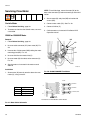
1
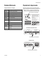
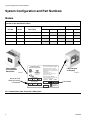
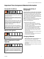
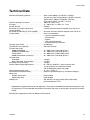
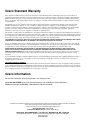
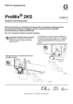
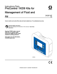
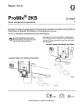
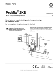
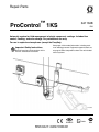
Repair-Parts
™
ProControl
3A1164B
1KS
ENG
Automatic system for fluid management of single component coatings. Includes flow
control, flushing, and color change. For professional use only.
For use in explosive atmospheres (except the EasyKey).
Important Safety Instructions
Read all warnings and instructions in this
manual. Save these instructions.
See pages 4-5 for model information, including maximum working pressure. Equipment approval labels are
on page 3. Some components shown are not included
with all systems.
TI16328a
#
53
II 2 G
Contents
Related Manuals . . . . . . . . . . . . . . . . . . . . . . . . . . . 3
Equipment Approvals . . . . . . . . . . . . . . . . . . . . . . . 3
System Configuration and Part Numbers . . . . . . . 4
Models . . . . . . . . . . . . . . . . . . . . . . . . . . . . . . . . 4
Warnings . . . . . . . . . . . . . . . . . . . . . . . . . . . . . . . . . 6
Important Two-Component Material Information . 9
Isocyanate Conditions . . . . . . . . . . . . . . . . . . . . . 9
Material Self-ignition . . . . . . . . . . . . . . . . . . . . . . 9
Keep Components A and B Separate . . . . . . . . . 9
Moisture Sensitivity of Isocyanates . . . . . . . . . . . 9
Changing Materials . . . . . . . . . . . . . . . . . . . . . . . 9
Grounding . . . . . . . . . . . . . . . . . . . . . . . . . . . . . . . 10
Check Resistance . . . . . . . . . . . . . . . . . . . . . . . . . 10
Pressure Relief Procedure . . . . . . . . . . . . . . . . . . 10
Troubleshooting . . . . . . . . . . . . . . . . . . . . . . . . . . . 13
Alarm Codes . . . . . . . . . . . . . . . . . . . . . . . . . . . 13
Solenoid Troubleshooting . . . . . . . . . . . . . . . . . 14
Wall Mount Fluid Manifold Troubleshooting . . . . 16
EasyKey Barrier Board Diagnostics . . . . . . . . . 17
EasyKey Display Board Diagnostics . . . . . . . . . 18
Discrete I/O Board Diagnostics . . . . . . . . . . . . . 20
Fluid Station Control Board Diagnostics . . . . . . 22
Color Change Board Diagnostics . . . . . . . . . . . 24
2
Schematic Diagrams . . . . . . . . . . . . . . . . . . . . . . . 26
System Pneumatic Schematic . . . . . . . . . . . . . . 26
EasyKey Electrical Schematic . . . . . . . . . . . . . . 27
System Electrical Schematic . . . . . . . . . . . . . . . 28
Service . . . . . . . . . . . . . . . . . . . . . . . . . . . . . . . . . . 30
Before Servicing . . . . . . . . . . . . . . . . . . . . . . . . 30
After Servicing . . . . . . . . . . . . . . . . . . . . . . . . . . 30
Servicing EasyKey . . . . . . . . . . . . . . . . . . . . . . . 31
Control Box . . . . . . . . . . . . . . . . . . . . . . . . . . . . 35
Servicing Flow Meter . . . . . . . . . . . . . . . . . . . . . 38
Servicing Color Change Module,
Color/Catalyst Valves, and Dump Valves . . 39
Servicing Flow Control . . . . . . . . . . . . . . . . . . . 40
Parts . . . . . . . . . . . . . . . . . . . . . . . . . . . . . . . . . . . . 43
ProControl 1KS System . . . . . . . . . . . . . . . . . . . 43
EasyKey Controls . . . . . . . . . . . . . . . . . . . . . . . 46
Available Cables . . . . . . . . . . . . . . . . . . . . . . . . 47
262363 Fluid Station Control Box . . . . . . . . . . . 48
262364 Valve Stack . . . . . . . . . . . . . . . . . . . . . . 50
249849 Flow Control Regulator . . . . . . . . . . . . . 51
Technical Data . . . . . . . . . . . . . . . . . . . . . . . . . . . . 53
Graco Standard Warranty . . . . . . . . . . . . . . . . . . . 54
Graco Information . . . . . . . . . . . . . . . . . . . . . . . . . 54
3A1164B
Related Manuals
Related Manuals
Equipment Approvals
Component Manuals in English
Equipment approvals appear on the following labels
which are attached to the Fluid Station Control Box and
EasyKey™. See FIG. 1 on page 4 for label locations.
Manual
Description
3A1163
3A1080
312782
312783
312787
312784
310745
312786
312785
308778
ProControl 1KS Installation
ProControl 1KS Operation
Dispense Valve
Color Change Valve Stacks
Color Change Module Kit
Gun Flush Box Kits
Gun Air Shutoff Kit
Dump Valve and Third Purge Valve Kits
Network Communication Kits
G3000/G3000HR/G250/G250HR Flow
Meter
Coriolis Flow Meter
Gun Flush Box Integration Kit
Floor Stand Kit
Beacon Kit
Basic Web Interface/Advanced Web
Interface
15V825 Discrete I/O Board Kit
313599
313212
313290
313542
313386
406800
EasyKey and Fluid Station Control Box Label
ATEX Certificate is listed here
ProControl 1KS
Electronic Proportioner
C
FM08ATEX0074
II 2 G
Ex ia IIA T3
US
Intrinsically safe
equipment for Class I,
Div 1, Group D, T3
Ta = -20°C to 50°C
Intrinsically Safe (IS) System. Install
per IS Control Drawing No. 289833.
EasyKey Interface IS Associated
Apparatus for use in non hazardous
location, with IS Connection to Smart
Fluid Plate IS
Apparatus for use in:
Class I, Division 1, Group D T3 C
Hazardous Locations
Read Instruction Manual
MAX AIR WPR
.7
MPa
7
100
bar
PSI
Warning: Substitution of components
may impair intrinsic safety.
PART NO.
SERIES
SERIAL
MAX FLUID WPR
1.31
13.1
190
MPa
bar
PSI
MFG. YR.
GRACO INC.
P.O. Box 1441
Minneapolis, MN
55440 U.S.A.
MAX TEMP 50°C (122°F)
Fluid Station Control Box Label
ProControl
PART NO.
SERIES
FLUID PANEL
MAX AIR WPR
SERIAL
Intrinsically safe equipment
for Class I, Div 1, Group D, T3
Ta = -20°C to 50°C
Install per 289833
.7
7
MPa
bar
100
PSI
GRACO INC.
P.O. Box 1441
Minneapolis, MN
55440 U.S.A.
FM08ATEX0073
II 2 G
Ex ia IIA T3
ATEX Certificate is listed here
EasyKey Label
ProControl 1KS
PART NO. SERIES NO. MFG. YR.
POWER REQUIREMENTS
VOLTS
85-250 ~
AMPS 2 AMPS MAX
277869
GRACO INC.
C
P.O. Box 1441
Minneapolis, MN
55440 U.S.A.
50/60 Hz
Intrinsically safe connections
for Class I, Div 1, Group D
US Ta = -20°C to 50°C
Install per 289833
II (2) G
[Ex ia] IIA
FM08ATEX0072
Um: 250 V
ATEX Certificate is listed here
3A1164B
3
System Configuration and Part Numbers
System Configuration and Part Numbers
Models
The part number for your equipment is printed on the equipment identification labels. See FIG. 1 for
location of the identification labels.
Meter
Part No.
Series
Description
None
262380
A
ProControl 1KS
✔
262381
A
ProControl 1KS
✔
262382
A
ProControl 1KS
✔
262383
A
ProControl 1KS
Electronic Proportioner
C
TI15974a
FM08ATEX0074
II 2 G
Ex ia IIA T3
Coriolis
No
US
Intrinsically safe
equipment for Class I,
Div 1, Group D, T3
Ta = -20°C to 50°C
Yes
✔
✔
✔
✔
ProControl 1KS
Label Location
on Fluid Station
Control Box
G3000
Flow Control
Intrinsically Safe (IS) System. Install
per IS Control Drawing No. 289833.
EasyKey Interface IS Associated
Apparatus for use in non hazardous
location, with IS Connection to Smart
Fluid Plate IS
Apparatus for use in:
Class I, Division 1, Group D T3 C
Hazardous Locations
✔
Label Location
on EasyKey
TI15975a
Read Instruction Manual
MAX AIR WPR
Maximum Fluid
Working Pressure
is listed here
.7
MPa
7
100
bar
PSI
Warning: Substitution of components
may impair intrinsic safety.
PART NO.
SERIES
SERIAL
Part Number
MAX FLUID WPR
1.31
13.1
190
MPa
bar
PSI
MAX TEMP 50°C (122°F)
MFG. YR.
GRACO INC.
P.O. Box 1441
Minneapolis, MN
55440 U.S.A.
FIG. 1: Identification Label, ProControl 1KS Systems
4
3A1164B
System Configuration and Part Numbers
Hazardous Location Approval
Models using a G3000, G3000HR, or intrinsically safe Coriolis meter are approved for installation in a Hazardous
Location - Class I, Div I, Group D, T3 or Zone I Group IIA T3.
Maximum Working Pressure
Maximum working pressure rating is dependent on the fluid component options selected. The pressure rating is
based on the rating of the lowest rated fluid component. Refer to the component pressure ratings below.
Example: Model 262383 has a maximum working pressure of 190 psi (1.31 MPa, 13.1 bar).
Check the identification label on the EasyKey or fluid station for the system maximum working pressure.
See FIG. 1.
ProMix Fluid Components Maximum Working Pressure
Base System (no meter, no color/catalyst change option,
and no flow control [option). . . . . . . . . . . . . . . . . . . . . . . . . . . . . . . . . . . . . . . . . . 4000 psi (27.58 MPa, 275.8 bar)
G3000 Meter Option . . . . . . . . . . . . . . . . . . . . . . . . . . . . . . . . . . . . . . . . . . . . . . 4000 psi (27.58 MPa, 275.8 bar)
Coriolis Meter Option . . . . . . . . . . . . . . . . . . . . . . . . . . . . . . . . . . . . . . . . . . . . . . 2300 psi (15.86 MPa, 158.6 bar)
Color Change Option . . . . . . . . . . . . . . . . . . . . . . . . . . . . . . . . . . . . . . . . . . . . . . . . . 300 psi (2.07 MPa, 20.6 bar)
Flow Control Option . . . . . . . . . . . . . . . . . . . . . . . . . . . . . . . . . . . . . . . . . . . . . . . . . . .190 psi (1.31 MPa 13.1 bar)
Flow Meter Fluid Flow Rate Range
G3000 . . . . . . . . . . . . . . . . . . . . . . . . . . . . . . . . . . . . . . . . . . . . . . . . . . . . . . . 75-3800 cc/min. (0.02-1.0 gal./min.)
G3000HR . . . . . . . . . . . . . . . . . . . . . . . . . . . . . . . . . . . . . . . . . . . . . . . . . . . 38-1900 cc/min. (0.01-0.50 gal./min.)
Coriolis Meter . . . . . . . . . . . . . . . . . . . . . . . . . . . . . . . . . . . . . . . . . . . . . . 20-3800 cc/min. (0.005-1.00 gal./min.)
S3000 Solvent Meter (accessory) . . . . . . . . . . . . . . . . . . . . . . . . . . . . . . . . 38-1900 cc/min. (0.01-0.50 gal./min.)
Standard Features
Accessories
Feature
Accessory
EasyKey with LCD
15V536 Solvent Flow Switch Kit
RS 485 Network Cable, 50 ft (15.25 m)
15V213 Power Cable, 100 ft (30.5 m)
Fiber Optic and Power Cables, 50 ft (15.25 m)
15G710 Fiber Optic Cable, 100 ft (30.5 m)
Fluid Station Control Box
15G614 Flow Control Extension Cable, 40 ft (12.2 m)
Discrete I/O Board
15W034 Strobe Light Alarm Indicator Kit
A Side Dump Valve, if color valve(s) selected
15V331 Gateway Ethernet Communication Kit
Flow Control with 15 ft (4.57 m) Cable (if selected)
15V963 Gateway DeviceNet Communication Kit
Basic Web Interface
15V964 Gateway Profibus Communication Kit
15V337 Advanced Web Interface
3A1164B
5
Warnings
Warnings
The following warnings are for the setup, use, grounding, maintenance, and repair of this equipment. The exclamation point symbol alerts you to a general warning and the hazard symbols refer to procedure-specific risks. When
these symbols appear in the body of this manual, refer back to these Warnings. Product-specific hazard symbols and
warnings not covered in this section may appear throughout the body of this manual where applicable.
WARNING
FIRE AND EXPLOSION HAZARD
Flammable fumes, such as solvent and paint fumes, in work area can ignite or explode. To help
prevent fire and explosion:
• Use equipment only in well ventilated area.
• Eliminate all ignition sources; such as pilot lights, cigarettes, portable electric lamps, and plastic
drop cloths (potential static arc).
• Keep work area free of debris, including solvent, rags and gasoline.
• Do not plug or unplug power cords, or turn power or light switches on or off when flammable fumes
are present.
• Ground all equipment in the work area. See Grounding instructions.
• Use only grounded hoses.
• Hold gun firmly to side of grounded pail when triggering into pail.
• If there is static sparking or you feel a shock, stop operation immediately. Do not use equipment
until you identify and correct the problem.
• Keep a working fire extinguisher in the work area.
ELECTRIC SHOCK HAZARD
This equipment must be grounded. Improper grounding, setup, or usage of the system can cause
electric shock.
• Turn off and disconnect power at main switch before disconnecting any cables and before servicing
equipment.
• Connect only to grounded power source.
• All electrical wiring must be done by a qualified electrician and comply with all local codes and
regulations.
INTRINSIC SAFETY
Intrinsically safe equipment that is installed improperly or connected to non-intrinsically safe equipment
will create a hazardous condition and can cause fire, explosion, or electric shock. Follow local
regulations and the following safety requirements.
• Only models with a G3000, G250, G3000HR, G250HR, or intrinsically safe Coriolis meter are
approved for installation in a Hazardous Location - Class I, Div I, Group D, T3 or Zone I Group IIA
T3.
• Do not install equipment approved only for a non-hazardous location in a hazardous area. See the
ID label for the intrinsic safety rating of your model.
•
6
Do not substitute or modify system components as this may impair intrinsic safety.
3A1164B
Warnings
WARNING
SKIN INJECTION HAZARD
High-pressure fluid from gun, hose leaks, or ruptured components will pierce skin. This may look like
just a cut, but it is a serious injury that can result in amputation. Get immediate surgical treatment.
• Do not spray without tip guard and trigger guard installed.
• Engage trigger lock when not spraying.
• Do not point gun at anyone or at any part of the body.
• Do not put your hand over the spray tip.
• Do not stop or deflect leaks with your hand, body, glove, or rag.
• Follow the Pressure Relief Procedure when you stop spraying and before cleaning, checking, or
servicing equipment.
• Tighten all fluid connections before operating the equipment.
• Check hoses and couplings daily. Replace worn or damaged parts immediately.
EQUIPMENT MISUSE HAZARD
Misuse can cause death or serious injury.
• Do not operate the unit when fatigued or under the influence of drugs or alcohol.
• Do not exceed the maximum working pressure or temperature rating of the lowest rated system
component. See Technical Data in all equipment manuals.
• Use fluids and solvents that are compatible with equipment wetted parts. See Technical Data in all
equipment manuals. Read fluid and solvent manufacturer’s warnings. For complete information
about your material, request MSDS from distributor or retailer.
• Do not leave the work area while equipment is energized or under pressure. Turn off all equipment
and follow the Pressure Relief Procedure when equipment is not in use.
• Check equipment daily. Repair or replace worn or damaged parts immediately with genuine
manufacturer’s replacement parts only.
• Do not alter or modify equipment.
• Use equipment only for its intended purpose. Call your distributor for information.
• Route hoses and cables away from traffic areas, sharp edges, moving parts, and hot surfaces.
• Do not kink or over bend hoses or use hoses to pull equipment.
• Keep children and animals away from work area.
• Comply with all applicable safety regulations.
3A1164B
7
Warnings
WARNING
TOXIC FLUID OR FUMES HAZARD
Toxic fluids or fumes can cause serious injury or death if splashed in the eyes or on skin, inhaled, or
swallowed.
• Read MSDSs to know the specific hazards of the fluids you are using.
• Store hazardous fluid in approved containers, and dispose of it according to applicable guidelines.
• Always wear chemically impermeable gloves when spraying, dispensing, or cleaning equipment.
PERSONAL PROTECTIVE EQUIPMENT
You must wear appropriate protective equipment when operating, servicing, or when in the operating
area of the equipment to help protect you from serious injury, including eye injury, hearing loss,
inhalation of toxic fumes, and burns. This equipment includes but is not limited to:
• Protective eyewear, and hearing protection.
• Respirators, protective clothing, and gloves as recommended by the fluid and solvent manufacturer.
8
3A1164B
Important Two-Component Material Information
Important Two-Component Material Information
Isocyanate Conditions
Spraying or dispensing materials containing isocyanates creates potentially harmful mists, vapors, and
atomized particulates.
Read material manufacturer’s warnings and material MSDS to know specific hazards and precautions
related to isocyanates.
Prevent inhalation of isocyanate mists, vapors, and
atomized particulates by providing sufficient ventilation in the work area. If sufficient ventilation is not
available, a supplied-air respirator is required for
everyone in the work area.
To prevent contact with isocyanates, appropriate
personal protective equipment, including chemically
impermeable gloves, boots, aprons, and goggles, is
also required for everyone in the work area.
Material Self-ignition
Some materials may become self-igniting if applied
too thickly. Read material manufacturer’s warnings
and material MSDS.
Keep Components A and B
Separate
Moisture Sensitivity of
Isocyanates
Isocyanates (ISO) are catalysts used in two component
coatings. ISO will react with moisture (such as humidity)
to form small, hard, abrasive crystals, which become
suspended in the fluid. Eventually a film will form on the
surface and the ISO will begin to gel, increasing in viscosity. If used, this partially cured ISO will reduce performance and the life of all wetted parts.
NOTE: The amount of film formation and rate of crystallization varies depending on the blend of ISO, the
humidity, and the temperature.
To prevent exposing ISO to moisture:
•
Always use a sealed container with a desiccant
dryer in the vent, or a nitrogen atmosphere. Never
store ISO in an open container.
•
Use moisture-proof hoses specifically designed for
ISO, such as those supplied with your system.
•
Never use reclaimed solvents, which may contain
moisture. Always keep solvent containers closed
when not in use.
•
Never use solvent on one side if it has been contaminated from the other side.
•
Always lubricate threaded parts with ISO pump oil
or grease when reassembling.
Changing Materials
•
When changing materials, flush the equipment multiple times to ensure it is thoroughly clean.
•
Always clean the fluid inlet strainers after flushing.
•
Check with your material manufacturer for chemical
compatibility.
•
Most materials use ISO on the A side, but some use
ISO on the B side.
Cross-contamination can result in cured material in
fluid lines which could cause serious injury or damage equipment. To prevent cross-contamination of
the equipment’s wetted parts, never interchange
component A (isocyanate) and component B (resin)
parts.
3A1164B
9
Grounding
Grounding
NOTE: If a Dose Time alarm (E-7, E-8) occurs, clear
the alarm.
3. Do a complete system purge, following the instructions under Purging Using Recipe 0, in the ProControl 1KS Operation Manual.
Your system must be grounded. See the Grounding
instructions in your ProControl 1KS Installation manual.
Check Resistance
4. Shut off the fluid supply to the solvent purge valve
(SPV) and the air supply to the air purge valve
(APV), FIG. 3.
5. With the gun triggered, push the manual override on
the A purge valve solenoid to relieve air and solvent
pressure. See FIG. 2. Verify that solvent pressure is
reduced to 0.
NOTE: If a Purge Volume alarm (E-11) occurs, clear
the alarm.
To ensure proper grounding, resistance between ProControl components and true earth ground must be
less than 1 ohm.
Have a qualified electrician check resistance between
each ProControl component and true earth ground. If
resistance is greater than 1 ohm, a different ground site
may be required. Do not operate the system until the
problem is corrected.
Systems with Color Change and Dump
Valves
NOTE: This procedure relieves pressure through the
dump valves.
1. Complete all steps under Single Color Systems,
page 10.
2. Shut off all color and catalyst supplies to the valve
stacks.
Pressure Relief
Procedure
NOTE: The following procedures relieve all fluid and air
pressure in the ProControl 1KS system. Use the procedure appropriate for your system configuration.
3. Press and hold the dump valve A solenoid override,
FIG. 2.
4. See FIG. 2. Open the color change module. Using
the solenoid identification labels as a guide, press
and hold the override button on each color solenoid
until flow from dump valve A stops.
5. Press and hold the dump valve A solenoid override,
FIG. 2.
Relieve pressure when you stop spraying, before
changing spray tips, and before cleaning, checking, or
servicing equipment.
6. Press and hold the A side (color) solvent solenoid
override until clean solvent comes from the dump
valve, then release.
7. Shutoff the solvent supply to the color/catalyst
change stack solvent valves.
Single Color Systems
1. While in Mix mode (gun triggered), shut off the fluid
supply pumps/pressure pots. Close all fluid shutoff
valves at the pump outlets.
8. Press and hold the A solvent solenoid override and
dump valve override until solvent flow from the
dump valve stops.
2. With the gun triggered, push the manual override on
the A dose valve solenoid to relieve pressure. See
FIG. 2.
10
3A1164B
Pressure Relief Procedure
Color
Solenoid
Identification
Label
Catalyst
Color
Solenoid
Identification
Label
TI12826a
Solvent Solenoid
Overrides
FIG. 2: Color Change Solenoids
Key:
FIH
MA Component A Meter
DVA Component A Dose
Valve
SPV Solvent Purge Valve
SS Solvent Purge Valve
Solvent Supply Tube
APV Air Purge Valve
AT
Air Purge Valve Air
Supply Tube
FIH Fluid Inlet Hose
FOH Fluid Outlet Hose
MA
APV
AT
DVA
SS
FOH
SPV
TI15977a
FIG. 3. Fluid Manifold
3A1164B
11
Pressure Relief Procedure
12
3A1164B
Troubleshooting
Troubleshooting
Table 1: System Alarm Codes
Code Description
Follow Pressure Relief Procedure, page 10, before
cleaning, checking, or servicing equipment.
NOTE: Do not use the fluid in the line that was dispensed off ratio as it may not cure properly.
Alarm Codes
Table 1 lists the system alarm codes. See the system
operation manual for complete information on alarm
troubleshooting.
3A1164B
E-1
Communication Error Alarm
E-2
Potlife Alarm
E-3
Ratio High Alarm
E-4
Ratio Low Alarm
E-5
Overdose A/B Dose Too Short Alarm
E-6
Overdose B/A Dose Too Short Alarm
E-7
Dose Time A Alarm
E-8
Dose Time B Alarm
E-9
Mix in Setup Alarm
E-10
Remote Stop Alarm
E-11
Purge Volume Alarm
E-12
CAN Network Communication Error Alarm
E-13
High Flow Alarm
E-14
Low Flow Alarm
E-15
System Idle Warning
E-16
Setup Change Warning
E-17
Power On Warning
E-18
Defaults Loaded Warning
E-19
I/O Alarm
E-20
Purge Initiate Alarm
E-21
Material Fill Alarm
E-22
Tank A Low Alarm
E-23
Tank B Low Alarm
E-24
Tank S Low Alarm
E-25
Auto Dump Complete Alarm
E-26
Color/Catalyst Purge Alarm
E-27
Color/Catalyst Fill Alarm
13
Troubleshooting
Solenoid Troubleshooting
Dose Valve A
Solenoid
Purge Valve B
Solenoid
Purge Valve A
Solenoid
Dose Valve B
Solenoid
J9
J3
J12
J1
J14
J15
J8
CAN
CAN
Power
Fiber
Optic
TI15916a
FIG. 4: Fluid Station Board and Solenoids
14
3A1164B
Troubleshooting
NOTE: Refer to the Schematic Diagrams, page 26.
If the dispense or purge valves are not turning on or off correctly, it could be caused by one of the following.
Cause
1. Air regulator pressure set too
high or too low.
Solution
Check air pressure. 80-90 psi (550-630 kPa, 5.5-6.3 bar) is commonly used.
Do not go below 70 psi (490 kPa, 4.9 bar) or above 120 psi (0.8 MPa, 8 bar).
2. Air or electrical lines damaged or Visually inspect air and electrical lines for kinks, damage, or loose connecconnections loose.
tions. Service or replace as needed.
3. Solenoid failure
Manually operate the valves by removing the Fluid Station cover and pressing and releasing solenoid valve override buttons. FIG. 4.
Use the control board diagnostics to check the signals. If signals do not
occur correctly, go to Cause 4.
Valves should snap open and shut quickly. If the valves actuate slowly, it
could be caused by:
• Air pressure to the valve actuators is too low. See Cause 1.
• Solenoid is clogged. Make sure air supply has 10 micron filter installed.
• Something is restricting the solenoid or tubing. Check for air output from
air line for corresponding solenoid when valve is actuated. Clear restriction.
• A dose valve is turned in too far. See ProControl 1KS Operation manual
for settings.
• Fluid pressure is high and air pressure is low.
4. Solenoid, cable, or fluid station
control board failure.
Check voltage level to solenoid by pulling solenoid connector and checking
voltage between pins.
If voltage is 9-15 VDC, the solenoid is damaged. Replace solenoid or correct
electrical line problem.
If there is no voltage, replace the board.
3A1164B
15
Troubleshooting
Wall Mount Fluid Manifold Troubleshooting
See FIG. 5.
Key:
MA Component A Meter
DVA Component A Dose
Valve
SPV Solvent Purge Valve
SS Solvent Purge Valve
Solvent Supply Tube
APV Air Purge Valve
AT
Air Purge Valve Air
Supply Tube
FIH Fluid Inlet Hose
FOH Fluid Outlet Hose
FIH
MA
APV
AT
DVA
SS
FOH
SPV
TI15977a
FIG. 5. Wall Mount Fluid Manifold
16
3A1164B
Troubleshooting
EasyKey Barrier Board Diagnostics
See FIG. 6 and Table 2 to troubleshoot the EasyKey barrier board. Also see the EasyKey Electrical Schematic on
page 27 and the System Electrical Schematic on pages 28 and 29.
J4, Pin 1
J1, Pin 1
D5
F1
F2
F4
F3
D4
J5, Pin 1
FIG. 6: 255786 EasyKey Barrier Board
Table 2: EasyKey Barrier Board Diagnostics
Connector Description
Diagnosis
J1
AC Power Input
n/a
J4
24 Vdc Power Input to
EasyKey Display Board
D5 turns on.
J5
12 Vdc Power Output to
Fluid Station Board
D4 turns on if barrier board is functioning. If D4 does not turn on, fuses F3
or F4 (Graco Part No. 15D979) are blown or there is no input power at J4.
If there is no input power (D5 does not light), fuses F1 and F2 (Graco Part
No. 114788) may be blown.
3A1164B
17
Troubleshooting
EasyKey Display Board Diagnostics
See FIG. 7 and Table 3 to troubleshoot the EasyKey display board. Also see the EasyKey Electrical Schematic on
page 27 and the System Electrical Schematic on pages 28 and 29.
J9
General Alarm
J10
Output Common
Integration Control
Potlife Alarm
TI12923a
Analog In Signal
Analog In Common
B
A
B
A
GND
GND
Multiple Station
D7
J5
Flow Control Calibrate
Gun Trigger
J1
Input Common
RT1
Remote Stop
P1
Reset Alarm
J6
TI12924a
BK885 or CR1220 Battery
(3V, 12.5 mm, lithium coin)
J4
D11
J7
J8
R5
FIG. 7: 255767 EasyKey Display Board
18
3A1164B
Troubleshooting
Table 3: EasyKey Display Board Diagnostics
Connector/
Indicator
Description
Connector/
Indicator
Description
J1
Graphic Display Backlight
J9
24 Vdc Power Input/Alarm Output
J4
Ribbon Cable to Membrane
J10
RS485 Communication Terminals
J5
Inputs and Outputs
D7 (green)
J6
Remote I/O
LED turns on when power is supplied to
board
J7
Fiber Optic Cable Input (black)
J8
Fiber Optic Cable Output (blue)
3A1164B
D11 (yellow) LED blinks (heartbeat) when board is
operating
P1
Ethernet Port
R5
Display Contrast/Dimmer Switch (turn
by hand)
19
Troubleshooting
Discrete I/O Board Diagnostics
See FIG. 8 and FIG. 9 to troubleshoot the Discrete I/O board. Also see the System Electrical Schematic on pages
28 and 29.
I/O Terminal Strip Detail
Pin 1
RS485 Integration A
RS485 Integration B
RS485 Integration Ground
RS485 Network A
RS485 Network B
RS485 Network Ground
Flow Control Calibrate
Pin 1
Gun Trigger
Digital Common
INPUTS
Remote Stop
Alarm Reset
General Alarm
Digital Common
OUTPUTS
Potlife Alarm
Flow Rate Analog In
Flow Rate Analog Common
TI12958a
Display Board
Barrier Board
Terminal Strips
(see detail above)
Discrete I/O Board
(see FIG. 9)
TI12496b
FIG. 8: EasyKey Control Boards and Terminal Strips
20
3A1164B
Digital Output
Common/Power
Special Output #1
Special Output #2
Special Output #3
Digital Output
Common/Power
Special Output #4
Troubleshooting
JLS
Digital Output Common/Power
Flow Rate Alarm Output
Flow Calibrate Active
Fill Active
Mix Ready Output
LED D1
(green)
Mix Active Output
Purge/Recipe Change Active Output
Digital Output Common/Power
Recipe Change Input
Recipe Bit 5 Input
Recipe Bit 4 Input
Recipe Bit 3 Input
Recipe Bit 2 Input
Recipe Bit 1 Input
Recipe Bit 0 Input
Digital Input Common
Spare
External Color Change Ready
Job Complete Input
Purge Input
Mix Input
Digital Input Common
FIG. 9: 255766 Discrete I/O Board
3A1164B
21
Troubleshooting
Fluid Station Control Board Diagnostics
See FIG. 10 and Table 4 to troubleshoot the fluid station control board. Also see the System Electrical Schematic
on pages 28 and 29.
J4
(Fiber Optic Output - blue)
J1, Pin 1
D18
D19
F1 (Fuse)
J6
(Fiber Optic Input black)
D15
J10
(Power Input)
D45
VDC
D16
J11
(Color Change
Module)
D46
D17
D20
J7
(Not Used)
D44
J9, Pin 1
D29
D43
D28 D30
J14, Pin 1
D27
J15, Pin 1
D41
D33
D31
J8, Pin 1
FIG. 10: 255765 Fluid Station Control Board
22
3A1164B
Troubleshooting
Table 4: Fluid Station Control Board Diagnostics
LED
Connector
and Pin Nos.
Signal Description
Diagnosis
D15
J1, 1 & 2
Air Flow Switch 1
Turns on when gun 1 is triggered.
D16
J1, 5 & 6
Solvent Flow Switch
Turns on when solvent is flowing.
D17
J1, 9 & 10
Gun Flush Box 2 Pressure Switch
Turns on when a gun is in Gun Flush Box 2.
D18
J10
Power
Turns on when power is supplied to the board.
D19
n/a
Communication (yellow)
Turns on when board is communicating with EasyKey.
D20
n/a
Board OK
Blinks (heartbeat) during normal operation.
D27
J15, 1 & 2
Purge Valve C (Water Purge)
D28
J14, 3 & 4
Purge Valve A (Air Purge)
D29
J8, 5 & 6
Dump Valve B
D30
J14, 5 & 6
Purge Valve B (Solvent Purge)
D31
J8, 1 & 2
Gun Flush Box 1 Trigger
D33
J8, 3 & 4
Gun Flush Box 2 Trigger
D41
J15, 5 & 6
Dump Valve A
D43
J9, 3 & 4
Dose Valve B
D44
J9, 1 & 2
Dose Valve A
D45
J1, 3 & 4
Air Flow Switch 2
Turns on when gun 2 is triggered.
D46
J1, 7 & 8
Gun Flush Box 1 Pressure Switch
Turns on when a gun is in Gun Flush Box 1.
F1
n/a
Replaceable Fuse
Check fuse condition if there is no power to the fluid
station.
3A1164B
D27 through D44 turn on when ProMix sends a signal
to actuate the related solenoid valve.
23
Troubleshooting
Color Change Board Diagnostics
See FIG. 11 and Table 5 to troubleshoot the color change board. Also see the System Electrical Schematic on
pages 28 and 29.
J8, Pin 1
D33
D34
D43
D31
D44
D29
J9, Pin 1
J15, Pin 1
D39
D41
D32
D35
D38
J16, Pin 1
D27
D37
J14, Pin 1
D45
D30
D46
D28
J10, Pin 1
D36
D9
D10
D8
F1 (Fuse)
J7
J11
FIG. 11: 256172 Color Change Board
24
3A1164B
Troubleshooting
Table 5: Color Change Board Diagnostics
LED
Connector
and Pin Nos.
Board 1 Signal
Description
Board 2 Signal
Description
Diagnosis
D8
n/a
Board OK
Board OK
Blinks (heartbeat) during normal operation.
D9
n/a
Communication
(yellow)
Communication
(yellow)
Turns on when board is communicating with ProMix
2KS.
D10
J7
Power
Power
Turns on when power is supplied to the board.
D27
J15, 5 & 6
Color 3
Color 16
D28
J14, 3 & 4
Color 1
Color 14
D29
J8, 5 & 6
Color 6
Color 19
D30
J14, 1 & 2
Color 2
Color 15
D31
J8, 3 & 4
Color 7
Color 20
D32
J16, 3 & 4
Catalyst 4
Color 26
D33
J8, 1 & 2
Color 8
Color 21
D34
J9, 5 & 6
Color 9
Color 22
D35
J15, 3 & 4
Color 4
Color 17
D36
J14, 5 & 6
Solvent (Color)
Color 13
D37
J10, 5 & 6
Catalyst 2
Color 28
D38
J16, 1 & 2
Catalyst 3
Color 27
D39
J16, 5 & 6
Color 12
Color 25
D41
J15, 1 & 2
Color 5
Color 18
D43
J9, 3 & 4
Color 10
Color 23
D44
J9, 1 & 2
Color 11
Color 24
D45
J10, 3 & 4
Catalyst 1
Color 29
D46
J10, 1 & 2
Solvent (Catalyst) Color 30
F1
Replaceable
Fuse
n/a
3A1164B
n/a
D27 through D46 turn on when ProMix 2KS sends
a signal to actuate the related solenoid valve.
Check fuse condition if there is no power to the
board or if communication is interrupted between
the fluid station and the color change module.
25
Schematic Diagrams
Schematic Diagrams
System Pneumatic Schematic
COLOR
CHANGE
CONTROL
AIR EXHAUST MUFFLER
COLOR 1
COLOR 2
COLOR 3
COLOR 4
COLOR 5
COLOR 6
COLOR 7
COLOR 8
COLOR SOLVENT
COLOR 9
COLOR 10
COLOR 11
COLOR 12
CATALYST 1
CATALYST 2
CATALYST 3
CATALYST 4
CATALYST SOLVENT
4-WAY SOLENOID
A B
E
E
OS
CL
UB
2T
5/3 N
E
OP
E
E
OS
CL
UB
2T
/
53 N
E
OP
DOSE A
VALVE
1/4 TUBE
12 VDC
A B
DOSE B
VALVE
12 VDC
05
CONTROL AIR
3/8 AIR FILTER
MANUAL DRAIN
5 MICRON
WALL MOUNT ONLY
4-WAY SOLENOID
AIR INPUT
PURGE A
VALVE
12 VDC
4-WAY SOLENOID
A B
E
E
OS
CL
UB
2T
5/3 EN
OP
PURGE B
VALVE
E
E
OS
CL
UB
2T
/
53 N
E
OP
PURGE C
VALVE
(OPTIONAL)
COLOR 13
COLOR 14
COLOR 15
COLOR 16
COLOR 17
COLOR 18
COLOR 19
COLOR 20
COLOR 21
COLOR 22
COLOR 23
COLOR 24
COLOR 25
COLOR 26
COLOR 27
COLOR 28
COLOR 29
COLOR 30
12 VDC
4-WAY SOLENOID
PURGE AIR
A B
E
E
OS
CL
UB
2T
5/3 N
E
OP
FLUSH AIR TO FLUID INLET
1/4 TUBE
TO MANIFOLD
12 VDC
4-WAY SOLENOID
COLOR
VALVE
STACKS
A B
AIR EXHAUST MUFFLER
12 VDC
3-WAY SOLENOID
E
A
UB
2T
5/3 N
E
OP
A
E
UB
2T
5/3 N
E
OP
DUMP A
VALVE
(OPTIONAL)
AIR INPUT
12 VDC
3-WAY SOLENOID
DUMP B
VALVE
(OPTIONAL)
MAC
36 SERIES SOLENOID VALVES
12 VDC
3-WAY SOLENOID
A
E
GFB 1
VALVE
(OPTIONAL)
E
GFB 2
VALVE
(OPTIONAL)
UB
2T
5/3 N
E
OP
MANIFOLD
12 VDC
3-WAY SOLENOID
26
A
UB
2T
5/3 N
E
OP
3A1164B
3A1164B
DISPLAY BOARD
P1
BARRIER BOARD
J9
1
2
3
4
RJ45
DISPLAY BOARD
RJ45
J5
J1
J4
24 VDC+
IN
RED 18 AWG
BLACK 18 AWG
RED/BLACK/WHITE 22 AWG
J5-1
J5-2
J5-3
SHIELD/GRND
COMMON (BLACK)
+12 VDC I/S (WHITE)
UNUSED
UNUSED
J1-1
UNUSED
J1-2
UNUSED
J1-4
J1-3
UNUSED
RED 18 AWG
BLACK 18 AWG
J1-5
J4-1
J4-2
J4-3
GREEN/BLACK/WHITE 22 AWG
IS POWER
12 VDC
+
+
+
+
-
RED 18 AWG
BLACK 18 AWG
DC OK
+
-
-
24 VDC+
HIGH
VOLTAGE
IN
POWER SUPPLY
24 VDC+
OUTPUT
GND LUG
COMMON
RJ45
BROWN 16 AWG
RED 16 AWG
RJ45 BULKHEAD
N
N
L
L
2
1
POWER
ROCKER SWITCH
2A
1A
+
-
BROWN 16 AWG
RED 16 AWG
ALARM
LINE FILTER
N
L1
N
L1
GND
N
L1
GND
TERMINAL BLOCKS
BROWN 16 AWG
RED 16 AWG
GRN/YEL 16 AWG
Schematic Diagrams
EasyKey Electrical Schematic
27
Schematic Diagrams
System Electrical Schematic
NOTE: The electrical schematic illustrates all possible wiring expansions in a ProMix 2KS system. Some components shown are not included with all systems.
Non-Hazardous Area
NON-HAZARDOUS AREA
OPERATOR INTERFACE
DC OK
+24 VDC
COMMON
COMMON
+
+
-
1
2
POWER
SUPPLY
POWER HARNESS
BARRIER
BOARD
J1
1
2
3
4
5
J5
1
2
3
J4
1
2
3
L1
N
L1 85-250 VAC
N
UNUSED
UNUSED
UNUSED
UNUSED
UNUSED
LINE
FILTER
L1
N
GND
OPEN
OPEN
HARNESS
+12VDC I/S (RED)
COM (BLACK)
SHIELD
L1 TERMINAL
N
BLOCK
GND
1
2
3
GND LUG
1
2
1A
1B
2A
2B
POWER
ROCKER
SWITCH
L1
N
GND
GND N L1
85-250
VAC
CABLE
+24VDC
OPEN
COMMON
(50' STD.)/
(100' OPTION)
ALARM
MEMBRANE
SWITCH
WITH
RIBBON
CABLE
J4
1
2
3
4
5
6
7
8
9
10
11
DISPLAY
BOARD
J6
J9
RJ45
1
2
3
4
+
-
+
-
RJ45
3'
POWER DIST.
TERMINAL
BLOCKS
J2
1
2
3
4
5
6
7
8
9
10
11
12
13
14
15
16
17
18
19
20
+
-
+
-
+
-
+
RJ45
1
2
3
4
J5 5
6
7
8
9
10
J2
J3
REMOTE
I/O
INTEGRATION
BOARD
SHIELD
DISPLAY
-
RJ45
FLOW CONTROL CAL. (BLK)
GUN TRIGGER (WHT)
DIGITAL IN COMMON (RED)
REMOTE STOP (GRN)
ALARM RESET (BRN)
ALARM OUTPUT (BLU)
DIGITAL OUTPUT COMMON (ORG)
POT LIFE (YEL)
FLOW RATE ANALOG IN (PUR)
FLOW RATE ANALOG COMMON (GRAY)
J4
1
2
3
4
5
6
7
8
9
10
1
2
3
4
5
6
1
2
3
4
5
6
7
8
MIX INPUT
PURGE INPUT
JOB COMPLETE INPUT
EXTERNAL CLR CHG READY
RESET ALARM INPUT
DIGITAL INPUT COMMON
DIGITAL INPUT COMMON
RECIPE BIT 0 INPUT
RECIPE BIT 1 INPUT
RECIPE BIT 2 INPUT
RECIPE BIT 3 INPUT
RECIPE BIT 4 INPUT
RECIPE BIT 5 INPUT
RECIPE CHANGE INPUT
1
2
3
4
5
6
7
8
DIGITAL OUTPUT COMMON/POWER
PURGE/RECIPE CHG ACTIVE OUTPUT
MIX ACTIVE OUTPUT
MIX READY OUTPUT
FILL ACTIVE
FLOW CAL. ACTIVE
FLOW RATE ALARM OUTPUT
DIGITAL OUTPUT COMMON/POWER
1
2
3
DIGITAL OUTPUT COMMON/POWER
SPECIAL OUTPUT #1
SPECIAL OUTPUT #2
SPECIAL OUTPUT #3
SPECIAL OUTPUT #4
DIGITAL OUTPUT COMMON/POWER
J5 4
5
6
I/O HARNESSES
J10
1
2
3
4
5
6
RS485 INTEGRATION A (WHT/BLU)
RS485 INTEGRATION B (BLU/WHT)
RS485 INTEGRATION GROUND (SHIELD)
RS485 NETWORK A (WHT/ORG)
RS485 NETWORK B (ORG/WHT)
RS485 NETWORK GROUND (SHIELD)
1
2
3
4
5
6
(+24) YEL
(COM) GRAY
ORG
BRN
RED
TERMINAL
BLOCKS
BEACON
CABLE
J7
J8
P1
RJ45
FO IN (BLK)
FO OUT (BLU)
RJ45
3'
RJ45
BULKHEAD
RJ45
RJ45
3'
(25'-200' OPTIONS)
28
WEB SERVER
MODULE
3A1164B
Schematic Diagrams
System Electrical Schematic
NOTE: The electrical schematic illustrates all possible wiring expansions in a ProMix 2KS system. Some components shown are not included with all systems.
Hazardous Area
HAZARDOUS AREA
FLUID PANEL CONTROL BOX
FLUID
PANEL
CONTROL
BOARD
J10
J3
J12
1
2
3
4
5
6
J13
+12VDC I/S
COM
SHIELD
2
3
5
3X CABLE
1
2
3
4
5
6
J5
MH2
J11
PWR (RED)
COM (BLACK)
SIG (WHITE)
SHIELD/GRN
NOT USED
NOT USED
NOT USED
NOT USED
PWR (RED)
COM (BLACK)
SIG (WHITE)
SHIELD/GRN
UNUSED
UNUSED
UNUSED
UNUSED
UNUSED
UNUSED
1
2
3
4
5
6
FLOW METER A
I.S. METERS
FLOW METER SOLVENT
V/P ANALOG OUT (WHT)
PRESS. (GRN)
+12 V (RED)
GND (BLK)
CHASSIS (BARE)
GROUND
TERMINAL
(10')/
(40')
1
2
3
4
5
6
3
2
5
4
1
6' STD.
(3'-100' OPTIONS)
CLR 8
GRD (BLK)
+12VDC (RED)
SHIELD (BARE)
CAN H (WHT)
CAN L (BLU)
50' STD.
3
2
5
4
1
MANIFOLD
CLR 7
CLR 6
3
2
5
4
1
GRD (BLK)
+12VDC (RED)
SHIELD (BARE)
CAN H (WHT)
CAN L (BLU)
CLR 4
BOOTH
CONTROL
BOARD
CLR 3
CLR 2
CLR 1
SOL CLR
J15
J14
J9
3A1164B
FO OUT
(BLU)
J4
FO IN
(BLK)
J6
J1
BLACK
RED
BLACK
RED
BLACK
RED
BLACK
RED
BLACK
RED
BLACK
RED
FLOW
CONTROL
BOARD
6
5
4
3
2
1
6
5
4
3
2
1
BLACK
RED
BLACK
RED
BLACK
RED
BLACK
RED
BLACK
RED
BLACK
RED
1
2
3
4
5
6
7
8
9
10
SIG
COM
SIG
COM
SIG
COM
SIG
COM
SIG
COM
DUMP A
J4
SIG (RED)
COM (BLK)
TECNO
V/P
+ PRESSURE (GRN)
COM (RED)
EX+ (WHT)
- PRESSURE (BLK)
SHIELD (BARE)
FLUID
PRESS.
SENS.
6
5
4
3
2
1
COM
+12VDC
COM
+12VDC
COM
+12VDC
+12VDC
COM
+12VDC
COM
+12VDC
COM
1
2
3
4
5
6
6
5
4
3
2
1
COM
+12VDC
COM
+12VDC
COM
+12VDC
CLR 12
+12VDC
COM
+12VDC
COM
+12VDC
COM
1
2
3
4
5
6
6
5
4
3
2
1
COM
+12VDC
COM
+12VDC
COM
+12VDC
CAT 2
J15
J14
J16
J10
MANIFOLD
CLR 9
CLR 10
CLR 11
CAT 4
CAT 3
CAT 1
SOL CAT
1 4 5 2 3
J7/J11
GFB #2
MANIFOLD
1
2
3
4
5
J2
+12VDC
COM
+12VDC
COM
+12VDC
COM
6' STD.
NOT USED
GFB #1
1
2
1 4 5 2 3
COLOR
BOARD 1
(COLORS
1 THRU 12,
CATALYST
1 1 THRU 4)
2
3
4 J8
J9
5
6
MANIFOLD
J7/J11
12 VDC
3-WAY SOLENOID
6
5
4
3
2
1
6
5
4
3
2
1
CLR 19
PURGE C
PURGE B
PURGE A
NOT USED
NOT USED
NOT USED
DOSE A
AIR FLOW SWITCH 1
AIR FLOW SWITCH 2
SOLVENT FLOW SWITCH
GFB 1 PRESSURE SWITCH
GFB 2 PRESSURE SWITCH
CLR 21
CLR 20
NOT USED
CLR 18
12 VDC
4-WAY SOLENOID
J8
1
2
3
4
5
J7/J11
CLR 5
J7
J1
CLR 17
CLR 16
CLR 15
CLR 14
CLR 13
MANIFOLD
1 4 5 2 3
COLOR
BOARD 2
(COLORS
13 THRU 30)
+12VDC
COM
+12VDC
COM
+12VDC
COM
1
2
3
4
5
6
+12VDC
COM
+12VDC
COM
+12VDC
COM
1
2
3
4 J15
5
6
+12VDC
COM
+12VDC
COM
+12VDC
COM
1
2
3
4 J14
5
6
J8
J9
J16
J10
MANIFOLD
6
5
4
3
2
1
COM
+12VDC
COM
+12VDC
COM
+12VDC
6
5
4
3
2
1
COM
+12VDC
COM
+12VDC
COM
+12VDC
CLR 25
6
5
4
3
2
1
COM
+12VDC
COM
+12VDC
COM
+12VDC
CLR 28
AFS #1 + (BLK)
AFS #1 - (WHT)
AFS #2 + (RED)
AFS #2 - (GRN)
PRESS. SWITCH #1 + (ORG)
PRESS. SWITCH #1 - (BLU)
PRESS. SWITCH #2 + (WHT/BLK)
PRESS. SWITCH #2 - (RED/BLK)
SOLENOID #1 +12 (GRN/BLK)
SOLENOID #1 COM (ORG/BLK)
SOLENOID #2 +12 (BLU/BLK)
SOLENOID #2 COM (RED/WHT)
1
2
3
4
5
6
7
8
9
10
11
12
CLR 22
CLR 23
CLR 24
CLR 26
CLR 27
CLR 29
CLR 30
ROBOMIX GFB
INTERFACE
MODULE
29
Service
Service
Before Servicing
3. Shut off ProControl 1KS power (0 position). FIG. 12.
4. If servicing EasyKey, also shut off power at main circuit breaker.
•
•
•
•
•
To avoid electric shock, turn off EasyKey power
before servicing.
Servicing EasyKey display exposes you to high
voltage. Shut off power at main circuit breaker
before opening enclosure.
All electrical wiring must be done by a qualified
electrician and comply with all local codes and regulations.
Do not substitute or modify system components as
this may impair intrinsic safety.
Read Warnings, page 6.
0 = OFF
TI12657a
FIG. 12: Power Off
NOTICE
To avoid damaging circuit board when servicing, wear
Part No. 112190 grounding strap on wrist and ground
appropriately.
1. Flush system and follow Pressure Relief Procedure, page 10, if service time may exceed pot life
time and before servicing fluid components.
After Servicing
After servicing the system, be sure to follow the
Start Up checklist and procedure in the ProControl 1KS
Operation manual.
2. Close main air shutoff valve on air supply line and
on ProControl 1KS.
30
3A1164B
Service
Servicing EasyKey
5. Disconnect graphic display power cable (J1) from
the display board (210c).
Updating Software
6. Separate graphic display (210b) from display board
(210c) [connector J2 on back of board].
To update software, upload new software from your PC
using the basic web interface. See manual 313386.
NOTE: If using the Graco Gateway in your system, disconnect its cable from the EasyKey before updating the
ProControl 1KS software.
7. To assemble the new parts, align connector J2 on
the display board (210c) with the socket on the
graphic display (210b). Press them together. See
FIG. 13.
8. Reconnect the graphic display power cable (J1) to
the display board (210c).
Replacing Display Board or Graphic
Display
9. Mount display board assembly with screws (210e).
10. Plug all connectors into display board (210c). FIG.
13. Confirm that the cables do not pinch when opening or closing the door.
NOTICE
To avoid damaging circuit board when servicing, wear
Part No. 112190 grounding strap on wrist and ground
appropriately.
11. Locate the battery on the board (see FIG. 7 on page
18). Pull the strip to remove the protective isolator
and activate the battery.
12. Close and lock EasyKey door with key.
13. Turn EasyKey power on to test display board.
1. Follow Before Servicing, page 30.
2. Unlock and open EasyKey door with its key.
Replacing Power Supply
3. Note position of all external connections (J4, J5, J6,
J7, J8, J9, J10) to display board, then unplug the
connectors. See FIG. 7 on page 18.
4. Remove 4 screws (210e) and the display board
assembly (210b, 210c). FIG. 13.
210a
210d
J1
1. Follow Before Servicing, page 30.
2. Unlock and open EasyKey door with its key.
3. Note position of power supply input and output
wires. See EasyKey Electrical Schematic, page
27. Disconnect wires from power supply (214f). See
FIG. 14.
4. Remove power supply from din rail.
5. Install new power supply (214f). Reconnect input
and output wires in positions noted in step 3.
210b
210c
210e
TI12554a
6. Close and lock EasyKey door with key.
7. Turn on power at main circuit breaker.
8. Turn EasyKey power on to test operation.
FIG. 13: Display Interface
3A1164B
31
Service
Replacing Line Filter
Replacing Power Switch
1. Follow Before Servicing, page 30.
1. Follow Before Servicing, page 30.
2. Unlock and open EasyKey door with its key.
2. Unlock and open EasyKey door with its key.
3. Note position of line filter input and output wires.
See EasyKey Electrical Schematic, page 27. Disconnect wires and remove line filter (214l) from
bracket (214m). See FIG. 14.
3. Note position of power switch wires. See EasyKey
Electrical Schematic, page 27. Disconnect wires
and remove switch (202, FIG. 14).
4. Install new line filter (214l). Reconnect wires in positions noted in step 3.
4. Install new power switch (202). Reconnect wires in
positions noted in step 3.
5. Close and lock EasyKey door with key.
5. Close and lock EasyKey door with key.
6. Turn on power at main circuit breaker.
6. Turn on power at main circuit breaker.
7. Turn EasyKey power on to test operation.
7. Turn EasyKey power on to test operation.
Power Supply
Outputs (Vdc)
214f
202
Power Supply
Inputs (Vac)
214l,
214m
Input Power
Terminal Block
TI13349b
FIG. 14: Power Supply
32
3A1164B
Service
Replacing Barrier Board
8. Install the cover (214b) with 2 screws (214k), using
the security tool.
9. Connect cables to J1, J4, and J5.
10. Close and lock EasyKey door with key.
11. Turn on power at main circuit breaker.
NOTICE
To avoid damaging circuit board when servicing, wear
Part No. 112190 grounding strap on wrist and ground
appropriately.
12. Turn EasyKey power on to test operation.
Replacing Barrier Board Fuses
1. Follow Before Servicing, page 30.
2. Unlock and open EasyKey door with its key.
3. Disconnect the cables and connectors from J1, J4,
and J5. FIG. 16.
4. Using the security tool provided (Part No. 122239),
remove 2 screws (214k) and the cover (214b). See
FIG. 15.
5. Noting their location, remove 5 screws (214g, 214h)
from the barrier board (214a). Do not remove the
screw noted in FIG. 16. Remove board.
Fuse
Part No.
Description
F1, F2
114788
Power In Fuses; 2 amp, time lag
F3, F4
15D979
Power Out Fuses; 0.4 amp, quick
acting
1. Follow Replacing Barrier Board, steps 1-4.
2. Remove the fuse (F1, F2, F3, or F4) from its fuse
holder. FIG. 16.
6. Apply thermal compound to the heatsink (Z) on the
back of the new barrier board (214a). FIG. 16.
3. Snap new fuse into holder.
7. Install the new barrier board with the 5 screws
(214g, 214h).
4. Follow Replacing Barrier Board, steps 8-12.
J4
J1
214c
214g
214b
J5
TI12649b
214k
214h
214g 214a
FIG. 15: Replacing Barrier Board
3A1164B
33
Service
J4 (Power to Display Board)
J1 (Power In)
214g
214g
F2
F1
F4
F3
214h
J5
(Power to Fluid Station)
214g
Do not remove
this screw
214h
Front of Barrier Board, showing Fuses and Connectors
1
1
Z
Apply thermal compound
to surface of heatsink (Z).
Back of Barrier Board, showing Heatsink (Z)
FIG. 16: Barrier Board Connectors and Fuses
34
3A1164B
Service
Control Box
2. Disconnect fiber optic wires (J4, J6) and all cables
(J1, J3, J5, J7, J8, J9, J10, J12, J14, J15) from control board (302). FIG. 17.
Replacing Control Board
3. Remove 4 screws (303). Remove connector jam
nuts on the outside of the enclosure (301). Remove
control board (302). FIG. 18.
4. Install new control board (302) with 4 screws (303).
NOTICE
To avoid damaging circuit board when servicing, wear
Part No. 112190 grounding strap on wrist and ground
appropriately.
1. Follow Before Servicing, page 30.
5. Connect cables to control board (302). FIG. 17.
Insert fiber optic cable connectors (J4, J6) into
board connectors (E), matching blue with blue, black
with black, and hand-tighten connectors. Do not
pinch or kink the fiber optic cables; the cables
require a 2 in. (51 mm) bend radius.
6. Turn EasyKey power on to test operation.
J4
(F.O. Output - blue)
F1 (343)
J6
(F.O. Input - black)
J1
(Digital Input)
J10
(Power Input)
J11
(Color Change Module)
J13
(Not Used)
J12
(Solvent Meter Input)
J3
(Meter A and B Input)
J9
(Solenoid Output:
Dose Valves A and B)
J14
(Solenoid Output:
Air Purge Valve and Solvent Flush Valve)
J7
(Not Used)
J5
(Flow Control)
J8
(Solenoid Output: Dump Valve B)
J15
(Solenoid Output:
3rd Flush Valve: Dump Valve A)
FIG. 17: 255765 Fluid Station Control Board
3A1164B
35
Service
309
310
311
330
TI15974a
301
313
326
303
304
302
334
306
305
320
343
F1
325
TI15916a
307
312
315
333
308
332
318
334
314
317
319
316
TI15917a
FIG. 18: Fluid Station Control Box
36
3A1164B
Service
Replacing Solenoids
The Fluid Station Control Box has a minimum of 4 solenoids. If you have options installed, you have additional
(optional) solenoids for each. See Table 6 and Schematic Diagrams, page 26.
To replace a single solenoid:
Table 6: Control Box Solenoids
Solenoid
Actuates
Standard
1
Dose Valve A
2
Dose Valve B
3
Air Purge Valve
4
Solvent Purge Valve
Optional
1. Follow Before Servicing, page 30, and shut off
power at main circuit breaker.
5
Third Flush Valve
6
Dump Valve A
7
Dump Valve B
2. Disconnect 2 solenoid wires from control board
(302). See FIG. 17 and System Electrical Schematic, page 29.
3. Unscrew 2 screws and remove solenoid (318). FIG.
19.
4. Install new solenoid (318).
5. Connect 2 wires (N) to control board (302). Solenoid
wires are polarized (red +, black –). Refer to System Electrical Schematic, page 29.
N
318
Replacing Control Board Fuse
TI15917a
Replacing the fuse with a non-Graco fuse voids the IS
system safety approval.
Fuse
Part No.
Description
F1
123690
Fuse; 125 mA, intrinsically safe
FIG. 19: Replacing Solenoids
1. Follow Before Servicing, page 30.
2. Locate fuse F1 on the control board. See FIG. 18.
Remove the screw and metal strap.
3. Pull the fuse away from the board.
4. Install the new fuse (343).
3A1164B
37
Service
Servicing Flow Meter
NOTE: To avoid leakage, secure the meter (M) to the
dose valve connector (H) before connecting it to the fluid
station.
2. Secure meter (M) and plate (MP) to bracket with
screws (MS).
Coriolis Meter
3. Connect meter cable (CC). See FIG. 20.
1. Follow Before Servicing, page 30.
4. Connect fluid line (P).
2. To remove and service the Coriolis meter, see manual 313599.
5. Calibrate meter as instructed in ProControl 1KS
Operation manual.
G3000 or G3000HR Meter
P
Removal
MS
1. Follow Before Servicing, page 30.
MP
2. Unscrew cable connector (CC) from meter (M). FIG.
20.
M
3. Unscrew four 1/4-20 screws (MS) holding the meter
mounting plate (MP). FIG. 20.
H
4. Unscrew fluid line from meter inlet (P).
5. Unscrew meter (M) from dose valve connector (H).
FIG. 20.
CC
6. Service meter as instructed in the meter manual
308778.
TI15977a
Installation
FIG. 20: G3000/G3000HR Flow Meters
1. Screw meter (M) securely onto the dose valve connector (H), using a wrench.
3X CABLE
J3*
Cable
241799
241800
241801
Length
5 ft (1.52 m)
16 in. (406 mm)
13 in. (330 mm)
J12 *
1
2
3
4
5
6
1
2
3
4
5
6
PWR (RED)
COM (BLACK)
SIG (WHITE)
SHIELD/GRN
PWR (RED)
COM (BLACK)
SIG (WHITE)
SHIELD/GRN
PWR (RED)
COM (BLACK)
SIG (WHITE)
SHIELD/GRN
FLOW METER A
FLOW METER B
FLOW METER SOLVENT
GROUND
TERMINAL
*Connectors on Fluid Station Control Board
FIG. 21: Meter Cable Schematic
38
3A1164B
Service
Servicing Color Change Module,
Color/Catalyst Valves, and
Dump Valves
1. Follow Before Servicing, page 30.
2. See manual 312787 for the color change module.
3. See manual 312783 for the color/catalyst valve
stacks.
4. See manual 312786 for the dump valve kits.
5. See manual 312782 to service an individual valve.
3A1164B
39
Service
Servicing Flow Control
6. Install a new o-ring (602) on the pressure sensor
(620) and screw the sensor into the fluid plate (606).
Preparation
7. Reinstall the fluid plate on the air plate. Be careful
not to pinch the pressure sensor cable. Torque the
screws (605) to 30-40 in-lb (3.4-4.5 N•m).
8. Reconnect the three cables to J1, J2, and J4 on the
circuit board (618). FIG. 22.
1. Follow Before Servicing, page 30.
2. Disconnect all air and fluid lines from the flow control regulator.
3. Disconnect the flow control cable from connector
(624). FIG. 23.
4. Remove the four screws (605) holding the air plate
(607) to the housing (611). Carefully lift the plate off
the housing and disconnect the three cables from
J1, J2, and J4 on the circuit board (618). FIG. 22.
Servicing the Regulator and Pressure
Sensor
Regulator Service Kit 15G843 is available. Kit parts are
marked with an asterisk, for example (602*). For best
results, use all parts in the kit.
Sensor Service Kit 15G867 is available to service the
pressure sensor only. Kit parts are marked with a symbol, for example (602‡). For best results, use all parts in
the kit.
1. Follow Preparation, above.
9. Reattach the air plate (607) to the housing (611).
Torque the screws (605) to 30-40 in-lb (3.4-4.5
N•m).
10. Reattach the flow control cable and all air and fluid
lines.
Servicing the Flow Control Board
1. Follow Before Servicing, page 30.
2. Remove the four screws (605) holding the bracket
(614) to the housing (611). FIG. 23.
3. Carefully separate the bracket from the housing and
disconnect the three cables from J1, J2, and J4 on
the circuit board (618). FIG. 22.
4. Remove the screws (621). Replace the old board
with the new board.
5. Reconnect the three cables to J1, J2, and J4 on the
circuit board (618). FIG. 22.
6. Reattach the bracket (614) to the housing (611).
Torque the screws (605) to 30-40 in-lb (3.4-4.5
N•m).
2. Remove the four screws (605) and the nut (601)
from the underside of the air plate (607). Separate
the air plate and fluid plate.
3. Unscrew the pressure sensor (620) from the fluid
plate (606).
NOTE: If you are only replacing the pressure sensor
kit 15G867, skip to step 6.
4. Remove the plug (615) and o-ring (604) from the top
of the fluid plate (606). Remove the parts of the diaphragm assembly (613, 610, 609, 612, 617, 616).
Remove and discard the dowels (623).
5. Reassemble the diaphragm assembly using the new
parts from the kit. Be sure the AIR SIDE of the diaphragm (617) faces down. Torque the nut (601) to
8-10 in-lb (0.9-1.1 N•m).
40
3A1164B
Service
Servicing the V/P Valve
615
1. Follow Before Servicing, page 30.
2. Remove the four screws (605) holding the bracket
(614) to the housing (611). FIG. 23.
3. Carefully separate the bracket from the housing and
disconnect the V/P valve cable from J2 on the circuit
board (618). FIG. 22.
*613
604*
*610
Flow
direction
606
4. Remove the two screws (619a) and o-rings (619b).
Install the new valve (619) with new screws and
o-rings.
*609
602*‡
*612
620*‡
*617
*623
*616
5. Reconnect the V/P valve cable to J2 on the circuit
board (618). FIG. 22.
6. Reattach the bracket (614) to the housing (611).
Torque the screws (605) to 30-40 in-lb (3.4-4.5
N•m).
601*
1
607
2
605
622
603
J2 (V/P Valve)
611
D7
D8
D9
R21
J2
C11
605
U5
2
R22
R3
R4 C12 L1
C10
J4
624
619b
U1
R27
R25
R20
U3
R7
619
621
618
J1
614
J4 (Pressure Sensor)
J1 (Power Input)
3
619a
605
FIG. 22: 249179 Flow Control Board
2
TI12506a
1
Torque to 8-10 in-lb (0.9-1.1 N•m)
2
Torque to 30-40 in-lb (3.4-4.5 N•m)
3
Torque to 5-7 in-lb (0.6 -0.8 N•m)
FIG. 23: Flow Control
3A1164B
41
Service
42
3A1164B
Parts
Parts
ProControl 1KS System
The part number for your equipment is printed on the equipment identification labels. See FIG. 1 for
location of the identification labels.
Meter
Part No.
Series
Description
None
262380
A
ProControl 1KS
✔
262381
A
ProControl 1KS
✔
262382
A
ProControl 1KS
✔
262383
A
ProControl 1KS
Electronic Proportioner
C
TI15974a
FM08ATEX0074
II 2 G
Ex ia IIA T3
Coriolis
No
US
Intrinsically safe
equipment for Class I,
Div 1, Group D, T3
Ta = -20°C to 50°C
Yes
✔
✔
✔
✔
ProControl 1KS
Label Location
on Fluid Station
Control Box
G3000
Flow Control
Intrinsically Safe (IS) System. Install
per IS Control Drawing No. 289833.
EasyKey Interface IS Associated
Apparatus for use in non hazardous
location, with IS Connection to Smart
Fluid Plate IS
Apparatus for use in:
Class I, Division 1, Group D T3 C
Hazardous Locations
✔
Label Location
on EasyKey
TI15975a
Read Instruction Manual
MAX AIR WPR
Maximum Fluid
Working Pressure
is listed here
.7
MPa
7
100
bar
PSI
PART NO.
SERIES
SERIAL
Part Number
MAX FLUID WPR
1.31
13.1
190
MPa
bar
PSI
MAX TEMP 50°C (122°F)
3A1164B
Warning: Substitution of components
may impair intrinsic safety.
MFG. YR.
GRACO INC.
P.O. Box 1441
Minneapolis, MN
55440 U.S.A.
43
Parts
Part No. 262380, without meter or flow control
Part No. 262381, with G3000 meter, without flow control
Part No. 262382, with G3000 meter and flow control
Part No. 262383, with Coriolis meter and flow control
5
2
3
24
2
336
335
17
4
1
11
2
9
10
8
2
Items 335 and 336 are part of the Fluid
Station Control Box. See the parts list
beginning on page 49 for descriptions.
TI16328a
Detail of Automatic Upgrade Kit (6)
6
44
6a
TI12496a
3A1164B
Parts
Part No. 262380, without meter or flow control
Part No. 262381, with G3000 meter, without flow control
Part No. 262382, with G3000 meter and flow control
Part No. 262383, with Coriolis meter and flow control
Ref.
No.
1
2
3
4
5
6
6a
8
9
Part No.
Description
262363
570122
114158
15G768
277869
15V256
15V825
262364
CONTROL BOX, fluid station; see page 48
MODULE, control, air
FITTING, tube, Y-adapter
PLUG, tube fitting
CONTROL/DISPLAY, EasyKey; see page 46
KIT, automatic upgrade; includes item 6a
• KIT, board, discrete I/O; part of item 6
VALVE STACK, dispense/purge, high pressure; see page 50
KIT, flow meter A
Model 262380
G3000 flow meter; see manual 308778; Models 262381 and
262382
KIT, Coriolis flow meter; see manual 313599; Model 262383
BRACKET, fluid station
Models 262380 and 262383
Models 262381 and 262382
REGULATOR, flow control; see page 51
Models 262380 and 262381
Models 262382 and 262383
CABLE, flow control; connects flow control regulator to fluid
station; 10 ft (3.0 m)
Models 262380 and 262381
Models 262382 and 262383
TUBING, polyethylene, 5/32 in. (4 mm) ID
none
16E955
15V806
10
none
16E841
11
none
249849
17
24
3A1164B
none
15G611
n/a
Qty
1
1
1
1
1
1
1
1
0
1
1
0
1
0
1
0
1
150 ft
45
Parts
EasyKey Controls
277869 EasyKey, with Display
206
Detail of Display Interface Kit (210)
214f
214c
208
201
210a
210d
202
214h
214l,
214m
210b
210c
210e
TI12554a
214g
214a
211
221
214b
TI12417b
214k
201
214d
214f
212
203
218
214l,
214m
209
214e,
214j
207
205, 206, 209
213, 223, 206
46
204
215
221
211
TI12496b
3A1164B
Parts
277869 EasyKey, with Display
Ref.
No.
Part No. Description
201
202
203
203a
204
205
206
n/a
116320
n/a
117818
111987
110911
111307
207
208
209
210
n/a
C19293
194337
15X779
210a
210b
210c
210d
210e
n/a
n/a
255767
n/a
n/a
211
212▲
213
214
15D568
15W776
223547
n/a
214a
255786
214b
214c
214d
214e
214f
n/a
117526
119257
114095
121314
214g
n/a
214h
n/a
214j
n/a
214k
n/a
3A1164B
CONTROL BOX, with display
SWITCH, power
LATCH; includes item 3a
• KEY
CONNECTOR, cord strain relief
NUT, hex; M5 x 0.8
WASHER, lock, external tooth;
M5
HOLDER, tie
NUT, hex
WIRE, grounding, door
KIT, display, interface; includes
items 210a, 210b, 210d, and
210e; does not include 210c
• MEMBRANE
• GRAPHIC, display
• BOARD, EasyKey display
• PLATE
• SCREW; 4-40 x 1 in. (25
mm)
ALARM
LABEL, warning
GROUND WIRE; 25 ft (7.6 m)
PLATE, application; includes
items 214a-214m
• BOARD, barrier, IS; (includes
fuses 15D979 and 114788,
see page 34 for fuse location)
• COVER
• SPACER
• BAR, ground
• BLOCK, terminal
• POWER SUPPLY; 24 Vdc;
2A
• SCREW, machine, pan-hd;
6-32 x 3/8 in. (10 mm)
• SCREW, machine, pan-hd;
6-32 x 1-1/2 in. (38 mm)
• SCREW, machine, pan-hd;
8-32 x 3/4 in. (19 mm)
• SCREW, machine, pan-hd;
10-24 x 3/8 in. (10 mm)
Qty
1
1
1
1
1
4
9
8
6
1
1
1
1
1
1
4
1
1
1
1
1
1
3
1
1
1
3
2
Ref.
No.
Part No. Description
Qty
214l
123823 • FILTER, line, single-phase;
110/250 V; 3 A
214m 123824 • BRACKET, line filter
215
15V280 HARNESS, connection
216
15G569 LABEL, EasyKey inputs
218
15R642 HARNESS, wire
220
n/a
SOFTWARE, application
221
198165 CONNECTOR, RJ45, with bulkhead fitting
223
116343 SCREW, ground; M5 x 0.8
224
15G869 CABLE, ethernet, CAT5; 6 ft
(1.8 m); to make web interface
connection to a computer
1
1
1
1
1
1
1
1
1
▲ Replacement Danger and Warning labels, tags, and
cards are available at no cost.
Parts labeled n/a are not available separately.
Available Cables
CAN Cables
Part No.
Length
ft (m)
15U531
2 (0.61)
Option
15U532
3 (0.92)
Standard color change
15V205
6 (1.83)
Option
15V206
10 (3.05)
Option
15V207
15 (4.57)
Option
15V208
25 (7.62)
Option
15U533
50 (15.25)
Standard power
15V213
100 (30.50)
Option
Usage
Fiber Optic Cables
Part No.
Length
Usage
15D320
50 (15.25)
Standard
15G710
100 (30.50)
Option
2
11
47
Parts
262363 Fluid Station Control Box
309
310
311
330
TI15974a
301
313
326
303
304
302
334
305
306
343
320
325
TI15916a
312
333
307
315
308
332
318
334
314
317
48
319
316
TI15917a
3A1164B
Parts
262363 Fluid Station Control Box
NOTE: Parts are shown on page 48, unless noted.
Ref.
No.
Part No. Description
301
302
303
16E380 ENCLOSURE
255765 BOARD, circuit
n/a
SCREW, machine, pan hd;
4-40 x 3/16 in. (5 mm)
304
119257 CONNECTOR, bar, ground
305
119162 CONNECTOR, plug, 6-position
306
116773 CONNECTOR, plug,10-position
307
121818 BULKHEAD, tube; 5/32 (4 mm)
308
111987 CONNECTOR, cord strain relief
309
112173 MUFFLER
310
C20497 FITTING, tube, bulkhead
311
16E434 PLATE, mounting, box
312
104176 BULKHEAD; 1/4 in. (6 mm) ID
tube
313▲ 186620 LABEL, symbol, ground
314
108382 FITTING, seal, o-ring; 10-32
315
120030 PLATE, blank, solenoid
316
120053 FITTING, tube; 10-32 x 1/4 in.
(6 mm) OD tube
317
112253 CONNECTOR, male
318
121795 VALVE, solenoid, 4-way, intrinsically safe; 12 Vdc
319
15U725 MANIFOLD, solenoid
320
113783 SCREW, machine, pan hd;
10-32 x 3/8 in. (10 mm)
3A1164B
Qty
1
1
4
1
6
1
12
5
1
1
1
1
2
5
4
3
12
4
1
4
Ref.
No.
Part No. Description
322
112925 SCREW, cap, button hd; 1/4-20
x 3/8 in. (10 mm)
325
116343 SCREW, ground
326▲ 15G809 LABEL, warning
329
112512 FERRULE
330
114158 FITTING, tube, Y-adapter
332
n/a
TUBE, nylon, red; 5/32 in.
(4 mm) OD; 4 ft (1.2 m)
333
n/a
TUBE, nylon, green; 5/32 in.
(4 mm) OD; 5 ft (1.5 m)
334
n/a
TUBE, nylon; 1/4 in. (6 mm)
OD; 2 ft (0.6 m)
335
15D320 CABLE, fiber-optic, twin; 50 ft
(15.25 m); see page 44 for
location
336
15U533 CABLE, CAN, intrinsically safe;
50 ft (15.25 m); see page 44 for
location
343◆ 123690 FUSE; 125 mA
Qty
2
1
1
4
1
A/R
A/R
A/R
1
1
1
▲ Replacement Danger and Warning labels, tags, and
cards are available at no cost.
◆ Replacing the fuse with a non-Graco fuse voids the
IS system safety approval.
Parts labeled n/a are not available separately.
49
Parts
262364 Valve Stack
Ref.
No.
401
402
403
404
405‡
406
407‡
408
409
410
411
Part No. Description
Qty
15X303 VALVE, high pressure;
includes item 413; see manual 312782
--SCREW; 5/16-24 x 5/8 in. (16
mm)
15T436 ADAPTER, manifold
101970 PLUG, pipe
109450 O-RING; ptfe
15T869 MANIFOLD, fluid port
--SEAT, valve needle; sst
110004 O-RING; ptfe
15T872 MANIFOLD, body
--SCREW, cap, socket-head;
1/4-20 x 5/8 in. (16 mm)
15T871 MANIFOLD, end cap
3
8
3
3
6
1
3
3
2
6
Ref.
No.
Part No. Description
412
413*‡
414
415
15T873
--15U927
C19800
416
104371
417
104116
Qty
PLATE, blank
O-RING; ptfe
BRACKET
SCREW, cap, socket-hd;
1/4-20 x 1/2 in. (13 mm)
SCREW, cap, socket-hd;
10-32 x 3/8 in. (10 mm)
WASHER, plain; no. 10
1
3
1
2
2
2
‡ Parts included in Valve Seat Kit 24A351 (purchase
separately). (Optional Carbide Seat Kit 15U932 is
available separately.)
*
1
Part included in Seal Kit 15U933 (purchase separately). Kit includes additional parts; see Dispense
Valve manual 312782.
--- These parts are not available separately.
417 416
414
410
411
402
415
‡407
404
408
*‡413
412
409
401
408
406
405‡
TI16356a
402
50
403
3A1164B
Parts
249849 Flow Control Regulator
Ref.
No.
Part No. Description
601*
102980
602‡* n/a
NUT, full, hex; 4-40
O-RING; chemically resistant
fluoroelastomer
603
112698 ELBOW; 1/8 npt(m) x 1/4 in.
(6 mm) OD tube
604*
n/a
O-RING; chemically resistant
fluoroelastomer
605
n/a
SCREW, cap, socket-hd;
10-32 x 1/2 in. (13 mm)
606
n/a
PLATE, fluid, regulator
607
15F799 PLATE, air, regulator
609*
n/a
SEAT, regulator
610*
n/a
RETAINER, seat
611
n/a
HOUSING, flow control
612*
n/a
SPACER, regulator
613*
n/a
NEEDLE, regulator
614
n/a
BRACKET, flow control
615
15F806 PLUG, regulator
616*
168881 GASKET; acetal
617*
178321 DIAPHRAGM, regulator
618
249179 BOARD, circuit assembly
619
120013 VALVE, proportional, V/P;
includes items 619a and 619b
619a n/a
• SCREW, cap, socket-hd;
M3 x 0.5 x 44 mm
619b 106560 • O-RING, mounting, size
007
620‡* n/a
SENSOR, pressure control
621
107295 SCREW, machine, pan-hd;
4-40 x 3/16 in. (5 mm)
622
104765 PLUG, pipe; 1/8 ptf
623*
192387 PIN, dowel
624
15G613 WIRE HARNESS, flow control
*
615
Qty
1
1
*613
604*
*610
Flow
direction
1
606
1
*609
602*‡
*612
620*‡
12
*617
1
1
1
1
1
1
1
1
1
1
1
1
1
*616
*623
601*
1
607
2
605
622
603
611
605
2
2
624
2
619b
1
4
619
621
618
1
2
1
3
619a
605
Parts included in Regulator Service Kit 15G843.
Purchase separately.
‡ Parts included in Sensor Service Kit 15G867.
Purchase separately.
614
2
TI12506a
Parts labeled n/a are not available separately.
3A1164B
1
Torque to 8-10 in-lbs (0.9-1.1 N•m)
2
Torque to 30-40 in-lbs (3.4-4.5 N•m)
3
Torque to 5-7 in-lbs (0.6 -0.8 N•m)
51
Parts
52
3A1164B
Technical Data
Technical Data
Maximum fluid working pressure . . . . . . . . . . . . . . . Base system: 4000 psi (27.58 MPa, 275.8 bar)
Low pressure color change: 300 psi (2.07 MPa, 20.6 bar)
Coriolis meter: 2300 psi (15.86 MPa, 158.6 bar)
Flow control: 190 psi (1.31 MPa, 13.1 bar)
Maximum working air pressure. . . . . . . . . . . . . . . . . 100 psi (0.7 MPa, 7 bar)
Air supply . . . . . . . . . . . . . . . . . . . . . . . . . . . . . . . . . 75 - 100 psi (0.5 - 0.7 MPa, 5.2 - 7 bar)
Air filter inlet size . . . . . . . . . . . . . . . . . . . . . . . . . . . 3/8 npt(f)
Air filtration for air logic and purge air
5 micron (minimum) filtration required; clean and dry air
(Graco-supplied). . . . . . . . . . . . . . . . . . . . . . . . . . . .
Air filtration for atomizing air (user-supplied) . . . . . . 30 micron (minimum) filtration required; clean and dry air
Fluids handled . . . . . . . . . . . . . . . . . . . . . . . . . . . . . one or two component:
• solvent and waterborne paints
• polyurethanes
• epoxies
• acid catalyzed varnishes
• moisture sensitive isocyanates
Viscosity range of fluid . . . . . . . . . . . . . . . . . . . . . . . 20- 5000 cps*
Fluid filtration (user-supplied) . . . . . . . . . . . . . . . . . . 100 mesh minimum
Fluid flow rate range*
G3000, G250 Meter . . . . . . . . . . . . . . . . . . . . . . 75 - 3800 cc/min. (0.02-1.00 gal./min.)
G3000HR, G250HR Meter. . . . . . . . . . . . . . . . . 38 - 1900 cc/min. (0.01-0.50 gal./min.)
Coriolis Meter. . . . . . . . . . . . . . . . . . . . . . . . . . . 20 - 3800 cc/min. (0.005-1.00 gal./min.)
S3000 Solvent Meter (accessory) . . . . . . . . . . . 38 - 1900 cc/min. (0.01-0.50 gal./min.)
Fluid inlet sizes
Flow Meter . . . . . . . . . . . . . . . . . . . . . . . . . . . . . 1/4 npt(f)
Dose Valve/Color Valve Adapters . . . . . . . . . . . 1/4 npt(f)
Fluid outlet size (static mixer) . . . . . . . . . . . . . . . . . . 1/4 npt(f)
External Power Supply Requirements . . . . . . . . . . . 85 - 250 Vac, 50/60 Hz, 2 amps maximum draw
15 amp maximum circuit breaker required
8 to 14 AWG power supply wire gauge
Operating temperature range . . . . . . . . . . . . . . . . . . 41- 122° F (5-50° C)
Environmental Conditions Rating . . . . . . . . . . . . . . . indoor use, pollution degree (2), installation category II
Noise Level
Sound pressure level . . . . . . . . . . . . . . . . . . . . . below 70 dBA
Sound power level . . . . . . . . . . . . . . . . . . . . . . . below 85 dBA
Wetted parts . . . . . . . . . . . . . . . . . . . . . . . . . . . . . . . 303, 304 SST, Tungsten carbide (with nickel binder),
perfluoroelastomer; PTFE
*
Dependent on programmed K-factor and application. The maximum allowable flow meter pulse frequency is 425
Hz (pulses/sec). For more detailed information on viscosities, flow rates, or mixing ratios, consult your Graco distributor.
See individual component manuals for additional technical data.
3A1164B
53
Graco Standard Warranty
Graco warrants all equipment referenced in this document which is manufactured by Graco and bearing its name to be free from defects in
material and workmanship on the date of sale to the original purchaser for use. With the exception of any special, extended, or limited warranty
published by Graco, Graco will, for a period of twelve months from the date of sale, repair or replace any part of the equipment determined by
Graco to be defective. This warranty applies only when the equipment is installed, operated and maintained in accordance with Graco’s written
recommendations.
This warranty does not cover, and Graco shall not be liable for general wear and tear, or any malfunction, damage or wear caused by faulty
installation, misapplication, abrasion, corrosion, inadequate or improper maintenance, negligence, accident, tampering, or substitution of
non-Graco component parts. Nor shall Graco be liable for malfunction, damage or wear caused by the incompatibility of Graco equipment with
structures, accessories, equipment or materials not supplied by Graco, or the improper design, manufacture, installation, operation or
maintenance of structures, accessories, equipment or materials not supplied by Graco.
This warranty is conditioned upon the prepaid return of the equipment claimed to be defective to an authorized Graco distributor for verification of
the claimed defect. If the claimed defect is verified, Graco will repair or replace free of charge any defective parts. The equipment will be returned
to the original purchaser transportation prepaid. If inspection of the equipment does not disclose any defect in material or workmanship, repairs will
be made at a reasonable charge, which charges may include the costs of parts, labor, and transportation.
THIS WARRANTY IS EXCLUSIVE, AND IS IN LIEU OF ANY OTHER WARRANTIES, EXPRESS OR IMPLIED, INCLUDING BUT NOT LIMITED
TO WARRANTY OF MERCHANTABILITY OR WARRANTY OF FITNESS FOR A PARTICULAR PURPOSE.
Graco’s sole obligation and buyer’s sole remedy for any breach of warranty shall be as set forth above. The buyer agrees that no other remedy
(including, but not limited to, incidental or consequential damages for lost profits, lost sales, injury to person or property, or any other incidental or
consequential loss) shall be available. Any action for breach of warranty must be brought within two (2) years of the date of sale.
GRACO MAKES NO WARRANTY, AND DISCLAIMS ALL IMPLIED WARRANTIES OF MERCHANTABILITY AND FITNESS FOR A
PARTICULAR PURPOSE, IN CONNECTION WITH ACCESSORIES, EQUIPMENT, MATERIALS OR COMPONENTS SOLD BUT NOT
MANUFACTURED BY GRACO. These items sold, but not manufactured by Graco (such as electric motors, switches, hose, etc.), are subject to
the warranty, if any, of their manufacturer. Graco will provide purchaser with reasonable assistance in making any claim for breach of these
warranties.
In no event will Graco be liable for indirect, incidental, special or consequential damages resulting from Graco supplying equipment hereunder, or
the furnishing, performance, or use of any products or other goods sold hereto, whether due to a breach of contract, breach of warranty, the
negligence of Graco, or otherwise.
FOR GRACO CANADA CUSTOMERS
The Parties acknowledge that they have required that the present document, as well as all documents, notices and legal proceedings entered into,
given or instituted pursuant hereto or relating directly or indirectly hereto, be drawn up in English. Les parties reconnaissent avoir convenu que la
rédaction du présente document sera en Anglais, ainsi que tous documents, avis et procédures judiciaires exécutés, donnés ou intentés, à la suite
de ou en rapport, directement ou indirectement, avec les procédures concernées.
Graco Information
For the latest information about Graco products, visit www.graco.com.
TO PLACE AN ORDER, contact your Graco distributor or call to identify the nearest distributor.
Phone: 612-623-6921 or Toll Free: 1-800-328-0211 Fax: 612-378-3505
All written and visual data contained in this document reflects the latest product information available at the time of publication.
Graco reserves the right to make changes at any time without notice.
Original instructions. This manual contains English. MM 3A1164
Graco Headquarters: Minneapolis
International Offices: Belgium, China, Japan, Korea
GRACO INC. AND SUBSIDIARIES • P.O. BOX 1441 • MINNEAPOLIS, MN • 55440-1441
Copyright 2010, Graco Inc. All Graco manufacturing locations are registered to ISO 9001.
www.graco.com
Revised 07/2011