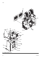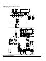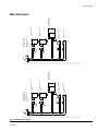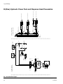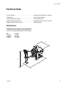
1
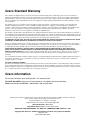
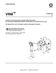
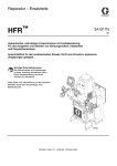
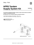
Repair - Parts
VRM™
313874E
EN
Hydraulic, Plural-component, Variable-Ratio Proportioner. For pouring and dispensing
sealants and adhesives. For professional use only.
Not approved for use in European explosive atmosphere locations.
Important Safety Instructions
Read all warnings and instructions in this
manual. Save these instructions.
See page 4 for model information, including maximum
working pressure and approvals.
ti17663a
Contents
Related Manuals . . . . . . . . . . . . . . . . . . . . . . . . . . . 3
Models . . . . . . . . . . . . . . . . . . . . . . . . . . . . . . . . . . . 4
Warnings . . . . . . . . . . . . . . . . . . . . . . . . . . . . . . . . . 5
Important Two-Component Material Information . 8
Isocyanate Conditions . . . . . . . . . . . . . . . . . . . . . 8
Material Self-ignition . . . . . . . . . . . . . . . . . . . . . . 8
Keep Components A (Red) and B (Blue) Separate 8
Moisture Sensitivity of Isocyanates . . . . . . . . . . . 8
Changing Materials . . . . . . . . . . . . . . . . . . . . . . . 9
A (Red) and B (Blue) Components . . . . . . . . . . . . . 9
Repair . . . . . . . . . . . . . . . . . . . . . . . . . . . . . . . . . . . 10
Linear Position Sensor Replacement . . . . . . . . 10
Hydraulic Driver Removal . . . . . . . . . . . . . . . . . 11
Dura-Flo Lower Removal . . . . . . . . . . . . . . . . . 12
Hydraulic Power Pack Repair . . . . . . . . . . . . . . 14
Parts . . . . . . . . . . . . . . . . . . . . . . . . . . . . . . . . . . . . 22
Systems, 24F391, 24F872, 24F873 . . . . . . . . . 22
Machine Base, 24C168 . . . . . . . . . . . . . . . . . . . 23
Power Pack Module . . . . . . . . . . . . . . . . . . . . . 27
Power Pack Module Sub-Assemblies . . . . . . . . 28
Vertical Driver Pumps . . . . . . . . . . . . . . . . . . . . 32
Hydraulic Vertical Actuator . . . . . . . . . . . . . . . . 34
Electrical Panels . . . . . . . . . . . . . . . . . . . . . . . . 35
Power Panel . . . . . . . . . . . . . . . . . . . . . . . . . . . 36
Fluid Control Panel . . . . . . . . . . . . . . . . . . . . . . 37
Applicator Assembly . . . . . . . . . . . . . . . . . . . . . 38
Mixer Manifold, 24F668 . . . . . . . . . . . . . . . . . . . 40
Mixer Assembly, 24H027 . . . . . . . . . . . . . . . . . 42
Floor Mounted Support . . . . . . . . . . . . . . . . . . . 43
Hoses . . . . . . . . . . . . . . . . . . . . . . . . . . . . . . . . 44
Logic Drawings . . . . . . . . . . . . . . . . . . . . . . . . . . . 45
230V 3 Phase Power Distribution Box . . . . . . . 45
400V 3 Phase Power Distribution Box . . . . . . . 46
B (Blue) Hydraulic Power Pack . . . . . . . . . . . . 47
A (Red) Hydraulic Power Pack . . . . . . . . . . . . . 48
Main Enclosure . . . . . . . . . . . . . . . . . . . . . . . . 49
B (Blue) Hydraulic Power Pack and Dispense Head
Pneumatics . . . . . . . . . . . . . . . . . . . . . . . . . 50
Technical Data . . . . . . . . . . . . . . . . . . . . . . . . . . . . 51
Dimensions . . . . . . . . . . . . . . . . . . . . . . . . . . . . 51
Graco Standard Warranty . . . . . . . . . . . . . . . . . . . 52
Graco Information . . . . . . . . . . . . . . . . . . . . . . . . . 52
2
313874E
Related Manuals
Related Manuals
Manuals are available at www.graco.com.
Component manuals in U.S. English:
System Manuals
313873
VRM Setup - Operation
Power Distribution Box Manual
3A0239
Power Distribution Boxes Instructions-Parts
Pumpline Manuals
3A0022
U-Cup Dura-Flo™ Lowers
3A0021
Vertical Hydraulic Driver
Repair-Parts
Feed System Manuals
3A1159
VRM Feed Systems
Valve Manuals
310550
1/2 in. NPT Fluid Port Ball Seat
Applicator
310551
3/4 in. NPT Fluid Port Ball Seat
Applicator
3A1792
DV Series Dispense Valves
313874E
3
Models
Models
System
24F872
60 A
230 (3)
24F391
55 A
400 (3)
55 A
400 (3)
24F873
*
approved
Full Load
Peak Amps Voltage
Per Phase* (phase)
✔
Approximate
Output per
Hydraulic Maximum Fluid
Max Flow
Cycle (A+B)** Pressure Working Pressure ‡
System Rate◆**
Ratio**
psi (MPa, bar)
Watts† lb/min (kg/min) gal. (liter)
24,000
66 (30)
1.0 (3.8)
1.63
2000 (14, 138)
Full load amps with all devices operating at maximum capabilities. Fuse requirements at various flow rates and
mix chamber sizes may be less.
** Values are dependent on installed pump size. Values shown are for largest available pump size.
◆ Flow rate is independent of frequency 50/60 Hz.
‡ If a motor control module is replaced, see Adjust Motor Control Module Selector Switch on page 16 to set the
machine to the proper maximum fluid working pressure.
4
313874E
Warnings
Warnings
The following warnings are for the setup, use, grounding, maintenance, and repair of this equipment. The exclamation point symbol alerts you to a general warning and the hazard symbol refers to procedure-specific risk. Refer back
to these warnings. Additional, product-specific warnings may be found throughout the body of this manual where
applicable.
WARNING
ELECTRIC SHOCK HAZARD
This equipment must be grounded. Improper grounding, setup, or usage of the system can cause electric shock.
•
Turn off and disconnect power at main switch before disconnecting any cables and before servicing
equipment.
• Connect only to grounded power source.
• All electrical wiring must be done by a qualified electrician and comply with all local codes and regulations.
TOXIC FLUID OR FUMES HAZARD
Toxic fluids or fumes can cause serious injury or death if splashed in the eyes or on skin, inhaled, or
swallowed.
•
•
•
Read MSDSs to know the specific hazards of the fluids you are using.
Store hazardous fluid in approved containers, and dispose of it according to applicable guidelines.
Always wear chemically impermeable gloves when spraying, dispensing, or cleaning equipment.
PERSONAL PROTECTIVE EQUIPMENT
You must wear appropriate protective equipment when operating, servicing, or when in the operating
area of the equipment to help protect you from serious injury, including eye injury, hearing loss, inhalation of toxic fumes, and burns. This equipment includes but is not limited to:
•
•
Protective eyewear, and hearing protection.
Respirators, protective clothing, and gloves as recommended by the fluid and solvent manufacturer.
SKIN INJECTION HAZARD
High-pressure fluid from dispensing device, hose leaks, or ruptured components will pierce skin. This
may look like just a cut, but it is a serious injury that can result in amputation. Get immediate surgical
treatment.
+
•
•
•
•
•
•
313874E
Do not point dispensing device at anyone or at any part of the body.
Do not put your hand over the fluid outlet.
Do not stop or deflect leaks with your hand, body, glove, or rag.
Follow the Pressure Relief Procedure when you stop dispensing and before cleaning, checking,
or servicing equipment.
Tighten all fluid connections before operating the equipment.
Check hoses and couplings daily. Replace worn or damaged parts immediately.
5
Warnings
WARNING
FIRE AND EXPLOSION HAZARD
Flammable fumes, such as solvent and paint fumes, in work area can ignite or explode. To help prevent
fire and explosion:
•
•
•
•
•
•
•
•
•
Use equipment only in well ventilated area.
Eliminate all ignition sources; such as pilot lights, cigarettes, portable electric lamps, and plastic
drop cloths (potential static arc).
Keep work area free of debris, including solvent, rags and gasoline.
Do not plug or unplug power cords, or turn power or light switches on or off when flammable fumes
are present.
Ground all equipment in the work area. See Grounding instructions.
Use only grounded hoses.
Hold gun firmly to side of grounded pail when triggering into pail.
If there is static sparking or you feel a shock, stop operation immediately. Do not use equipment
until you identify and correct the problem.
Keep a working fire extinguisher in the work area.
EQUIPMENT MISUSE HAZARD
Misuse can cause death or serious injury.
•
•
•
•
•
•
•
•
•
•
•
6
Do not operate the unit when fatigued or under the influence of drugs or alcohol.
Do not exceed the maximum working pressure or temperature rating of the lowest rated system
component. See Technical Data in all equipment manuals.
Use fluids and solvents that are compatible with equipment wetted parts. See Technical Data in all
equipment manuals. Read fluid and solvent manufacturer’s warnings. For complete information
about your material, request MSDS from distributor or retailer.
Do not leave the work area while equipment is energized or under pressure. Turn off all equipment
and follow the Pressure Relief Procedure when equipment is not in use.
Check equipment daily. Repair or replace worn or damaged parts immediately with genuine manufacturer’s replacement parts only.
Do not alter or modify equipment.
Use equipment only for its intended purpose. Call your distributor for information.
Route hoses and cables away from traffic areas, sharp edges, moving parts, and hot surfaces.
Do not kink or over bend hoses or use hoses to pull equipment.
Keep children and animals away from work area.
Comply with all applicable safety regulations.
313874E
Warnings
WARNING
MOVING PARTS HAZARD
Moving parts can pinch, cut or amputate fingers and other body parts.
•
•
•
Keep clear of moving parts.
Do not operate equipment with protective guards or covers removed.
Pressurized equipment can start without warning. Before checking, moving, or servicing equipment, follow the Pressure Relief Procedure and disconnect all power sources.
BURN HAZARD
Equipment surfaces and fluid that’s heated can become very hot during operation. To avoid severe
burns:
• Do not touch hot fluid or equipment.
313874E
7
Important Two-Component Material Information
Important Two-Component Material Information
Isocyanate Conditions
Spraying or dispensing materials containing isocyanates creates potentially harmful mists, vapors, and
atomized particulates.
Read material manufacturer’s warnings and material
MSDS to know specific hazards and precautions
related to isocyanates.
Prevent inhalation of isocyanate mists, vapors, and
atomized particulates by providing sufficient ventilation in the work area. If sufficient ventilation is not
available, a supplied-air respirator is required for
everyone in the work area.
To prevent contact with isocyanates, appropriate personal protective equipment, including chemically
impermeable gloves, boots, aprons, and goggles, is
also required for everyone in the work area.
Material Self-ignition
Moisture Sensitivity of
Isocyanates
Isocyanates (ISO) are catalysts used in two component
foam and polyurea coatings. ISO will react with moisture
(such as humidity) to form small, hard, abrasive crystals,
which become suspended in the fluid. Eventually a film
will form on the surface and the ISO will begin to gel,
increasing in viscosity. If used, this partially cured ISO
will reduce performance and the life of all wetted parts.
NOTE: The amount of film formation and rate of crystallization varies depending on the blend of ISO, the
humidity, and the temperature.
To prevent exposing ISO to moisture:
•
•
•
•
Some materials may become self-igniting if applied
too thickly. Read material manufacturer’s warnings
and material MSDS.
•
•
Always use a sealed container with a desiccant
dryer in the vent, or a nitrogen atmosphere. Never
store ISO in an open container.
Keep the pump wet cups filled with IsoGuard
Select®, part 24F516. The lubricant creates a barrier between the ISO and the atmosphere.
Use moisture-proof hoses specifically designed for
ISO, such as those supplied with your system.
Never use reclaimed solvents, which may contain
moisture. Always keep solvent containers closed
when not in use.
Never use solvent on one side if it has been contaminated from the other side.
Always lubricate threaded parts with ISO pump oil
or grease when reassembling.
Keep Components A (Red) and
B (Blue) Separate
Cross-contamination can result in cured material in
fluid lines which could cause serious injury or damage equipment. To prevent cross-contamination of
the equipment’s wetted parts, never interchange
component A (Red) and component B (Blue) parts.
8
313874E
A (Red) and B (Blue) Components
Changing Materials
•
When changing materials, flush the equipment multiple times to ensure it is thoroughly clean.
•
Always clean the fluid inlet strainers after flushing.
•
Check with your material manufacturer for chemical
compatibility.
•
Most materials use ISO on the A (Red) side, but
some use ISO on the B (Blue) side. See the following section.
A (Red) and B (Blue) Components
IMPORTANT!
Material suppliers can vary in how they refer to plural
component materials.
Be aware that when standing in front of the manifold on
proportioner:
•
•
Component A (Red) is on the left side.
Component B (Blue) is on the right side.
For all machines:
•
•
The A (Red) side is intended for ISO, hardeners,
and catalysts.
The B (Blue) side is intended for polyols, resins, and
bases.
NOTE: For machines with material volume ratios other
than 1:1, the higher volume side is typically the B (Blue)
side.
313874E
9
Repair
Repair
Linear Position Sensor Replacement
713
718
711
704 9
2 722, 723
710 4
708
3 707
716 4
9 701
712 4
702
715 5
706 1
714 6
3
708
705
ti17670a
1
Torque to 100 ft-lb (135 N•m).
6
Torque to 10-12 in-lb (1.1-1.4 N•m).
2
Torque to 350 in-lb (39.5 N•m).
7
Apply thread sealant to threads.
3
Apply a light coating of lubricant to seals and
surfaces specified.
8
Torque to 30-36 ft-lb (41-49 N•m).
4
9
Torque to 50-60 ft-lb (68-81 N•m).
5
Apply adhesive to surfaces specified.
Orient ref 701 with date code on casting
opposite of 0.25 diameter hole as shown. Ref
704 to be on opposite side of 0.25 diameter
hole as shown.
FIG. 1
NOTE: See FIG. 1 for part references.
1. Perform Shutdown procedure. See operation manual for procedure.
2. Remove pumpline shield.
5. Use a 1-1/4 in. wrench to loosen the linear position
sensor. Remove the linear position sensor.
6. Carefully insert the new linear position sensor
through the hole in the plate (713) and into the vertical hydraulic driver. Use a 1-1/4 in. wrench to gently
tighten.
3. Insert a large allen wrench through the center of the
lift ring (717) then twist to loosen. Remove lift ring.
4. Disconnect linear position sensor cable. Route the
cable through the hole in the plate (713) directly
above the linear position sensor (718).
10
313874E
Repair
Hydraulic Driver Removal
NOTE: This procedure details how to remove the
hydraulic driver. Hydraulic driver rebuild information is in
the hydraulic driver manual.
622
620
619
618
604
3
621
623
_1c
ti17669a
604 3
601
2
605
4
606 1
603 3 2
607
Isometric View
608 1
1
Torque 50-60 ft-lb (68-81 N•m).
3
Apply thread lubricant.
2
Torque 145-155 ft-lb (196-210 N•m).
4
Apply thread sealant.
602
613
FIG. 2
NOTE: See FIG. 1 and FIG. 2 for part references.
7. Remove the drip fittings connected to the base of
the vertical hydraulic actuator.
1. Perform Shutdown and Pressure Relief Procedure procedures. See operation manual for procedures.
8. Remove four screws (705) connecting hydraulic
driver to vertical actuator housing (704).
2. Remove the pump shield.
9. Remove three screws (706) that connect the bottom
plate (702) to the rest of the hydraulic driver.
3. Remove three screws (716). Remove top
plate (713).
10. Remove the hydraulic driver (701).
4. Remove three tie rods (712). Remove plate (711)
with linear position sensor (718).
5. Remove three tie rods (710).
11. See hydraulic driver manual for rebuild information.
NOTE: Install hydraulic driver in reverse order. See
notes in the applicable parts illustrations for torque and
other specifications.
6. Loosen the coupling nut (603) to disconnect the
actuator and pump rods.
313874E
11
Repair
Dura-Flo Lower Removal
NOTE: This procedure details how to remove the
Dura-Flo Lower. Rebuild information is in the Dura-Flo
Lower manual.
622
620
619
618
604
3
621
623
_1c
ti17669a
604 3
601
2
605
4
606 1
603 3 2
607
Isometric View
608 1
1
Torque 50-60 ft-lb (68-81 N•m).
3
Apply thread lubricant.
2
Torque 145-155 ft-lb (196-210 N•m).
4
Apply thread sealant.
602
613
FIG. 3
See FIG. 3 for part references.
1. Perform Shutdown and Pressure Relief Procedure procedures. See operation manual for procedures.
NOTE: Install Dura-Flow Lower in reverse order. See
notes in the applicable parts illustrations for torque and
other specifications.
2. Loosen the coupling nut (603) to disconnect the
hydraulic vertical actuator and pump rods.
3. Use a large adjustable wrench to remove the large
inlet feed fittings at the base of the Dura-Flo Lowers.
4. Remove three screws (608).
5. Remove Dura-Flo Lower.
6. See Dura-Flo Lower manual for rebuild information.
12
313874E
Repair
313874E
13
Repair
Hydraulic Power Pack Repair
435 8
434 26
11
403
6
415 2
6
7
12
421, 422
5
14
445
11
431
11
11
432
433
11
15
430
429
428
446 11
418
417 2
416 10
12
419
404 3
11
406 5
444
414 10
421,
427 4
405
2
40912
437
11
410 2
12
2
41212
426
411
401
413 10
408 3
11
8
423 9
11
12
425
9
424
438
402
10
13
407
406 1
+.01
.30 -.00
420
436
Assemble coupler to specified dimensions
prior to mounting assembly to housing.
2
Torque to 40 ft-lb (54 N•m).
3
Torque to 35 ft-lb (47 N•m).
4
Torque to 20 ft-lb (27 N•m).
5
Torque to 15 ft-lb (20 N•m).
6
Torque to 10 ft-lb (14 N•m).
7
Torque to 58 in-lb (6.5 N•m).
431 24
+.00
.45 -.02
402 1
448, 449
1
_1j
8
Torque to 34 in-lb (3.8 N•m).
9
Torque 1/4 turn past hand-tight.
15
Prior to installing Ref. 428 into Ref. 426,
install Ref. 429 into Ref. 428 and adjust
head 1/8 in. from surface.
10
Apply PTFE tape on installation end only.
24
Align fan plug as shown.
11
Apply sealant to threads.
26
Apply thermal lubricant to contact side.
12
Apply light coating of lubricant to seals.
13
Fill reservoir with hydraulic fluid.
14
Orient with airflow arrow pointing toward
mounting bracket.
FIG. 4: Hydraulic DC Power Pack
14
313874E
Repair
Remove Hydraulic Power Pack Shroud
Replace Fan
1. Remove four screws from base of shroud.
2. Lift shroud off of Hydraulic Power Pack.
Install Hydraulic Power Pack Shroud
NOTICE
Do not over-torque any item that threads into the
hydraulic tank. This will strip the threads and
require tank replacement.
1. Place shroud on top of Hydraulic Power Pack.
See FIG. 4 on page 14.
1. Perform Shutdown procedure. See operation manual for procedure.
2. Remove Hydraulic Power Pack Shroud, see procedure on this page.
3. Remove four screws (432) connecting fan to mounting plate.
2. Install four screws securing shroud to hydraulic tank.
4. Remove fan and install new fan.
Replace Hydraulic Filter
Filter is located at right rear of hydraulic power pack.
See FIG. 4 on page 14.
NOTICE
If any debris falls into the hydraulic tank, the debris
must be removed or machine damage will result.
5. Install four screws (432) connecting fan to Motor
and Motor Control Module.
6. Install Hydraulic Power Pack Shroud, see procedure on this page.
Remove Motor Control Module
1. Perform Shutdown procedure. See operation manual for procedure.
2. Use compressed air to remove any loose debris
around the hydraulic filter.
See FIG. 4 on page 14.
3. Remove new filter from wrapping.
1. Perform Shutdown procedure. See operation manual for procedure.
4. Apply a light coat of hydraulic fluid to the o-ring on
the face of the hydraulic filter.
2. Remove Hydraulic Power Pack Shroud, see procedure on this page.
5. Being careful not to allow any debris into the
hydraulic tank remove old filter from tank then
quickly install new filter.
3. Remove four screws (432) connecting fan to Motor
and Motor Control Module. Remove fan and mounting plate.
4. Note the location of each Motor Control Module
cable then remove all electrical cables on the left
and right sides of the Motor Control Module.
5. Remove six screws (429) securing Motor Control
Module in place.
6. Slowly and carefully slide the Motor Control Module
up until the cable on the bottom of the Motor Control
Module can be accessed and removed. Disconnect
the cable.
7. Slide the Motor Control Module up and remove.
313874E
15
Repair
Adjust Motor Control Module Selector
Switch
4. Install access cover (D).
NOTICE
D
If the Motor Control Module is replaced, the selector switch must be set prior to initial startup of the
Motor Control Module or damage may occur.
The Motor Control Module uses an 8-position selector
switch (S) to set system maximum working pressure.
See FIG. 5.
The system must be configured to have a maximum
working pressure of 2000 psi (13.8 MPa, 138 bar). Set
the selector switch according to the following table.
MCM
Switch Position
B (Blue)
1
A (Red)
2
The selector switch position will be properly set at the
factory for new systems. When a motor control module
is replaced, the selector switch must be set to the correct setting by the user prior to initial startup.
S
257396_3b9905_04b
FIG. 5
Install Motor Control Module
This procedure starts assuming that the old Motor Control Module is removed from the machine. See Remove
Motor Control Module procedure, see page 15.
See FIG. 4 on page 14.
1. Perform Adjust Motor Control Module Selector
Switch procedure on page 16.
NOTICE
•
•
Do not install components rated to less than the
maximum working pressure. Doing so may lead to
overpressurization and ruptured components.
High-pressure fluid from ruptured components will
pierce skin. This may look like just a cut, but it is a
serious injury that can result in amputation. Get
immediate surgical treatment.
To set the Motor Control Module selector switch:
1. Turn machine power off.
2. Remove the access cover (D). See FIG. 5.
3. Set the selector switch (S).
Motor Control Module selector switch position must
be set prior to startup of Motor Control Module or
damage may occur.
2. Slide the Motor Control Module into the slot.
3. Attach the cable on the bottom of the Motor Control
Module.
4. Install the six screws (429) securing Motor Control
Module in place.
5. Install electrical cables on left and right sides of the
Motor Control Module.
6. Install four screws (432) connecting fan to Motor
and Motor Control Module. Install fan and mounting
plate.
7. Install Hydraulic Power Pack Shroud, see procedure on page 15.
16
313874E
Repair
Remove Hydraulic Power Pack
The hydraulic power pack weighs up to 300 lb. To
avoid serious injury due the hydraulic power pack falling, secure the hydraulic lift when raising the hydraulic
power pack.
6. Remove the two bolts (446) from the fluid
housing (403) and replace each with a strong
5/16-18 thread eye-bolt. Install a third strong
5/16-18 eye-bolt as indicated. See FIG. 6. See FIG. 4
on page 14 for full hydraulic power pack view.
403
446
446
NOTICE
If any debris falls into the hydraulic tank, the debris
must be removed or machine damage will result.
_1j1
Install third eye-bolt here
This procedure removes the hydraulic power pack from
the machine as a single unit to enable further disassembly. User must purchase three 5/16-18 eye-bolts capable
of holding 300 lb to perform this procedure.
FIG. 6
See FIG. 4 on page 14.
7. Run a rope through the three eye-bolts and between
the motor and the Motor Control Module. Secure to
a hydraulic lift.
1. Perform Shutdown procedure. See operation manual for procedure.
2. Perform Remove Hydraulic Power Pack Shroud,
see procedure on page 15.
3. Perform Remove Motor Control Module procedure, see page 15.
8. Remove the four bolts (304) and washers (303)
securing the tank to the electrical enclosure. See
Power Pack Module on page 27.
9. Lift the hydraulic power pack and place on a sturdy
location capable of supporting up to 300 lb (136 kg).
4. Remove four screws (705) to disconnect hydraulic
vertical actuator from hydraulic power pack. See
FIG. 1 on page 10.
5. Disconnect heat exchanger inlet hose and fitting
from elbow fitting (417). Disconnect heat exchanger
outlet hose and fitting from elbow fitting (425).
313874E
17
Repair
Install Hydraulic Power Pack
NOTICE
If any debris falls into the hydraulic tank, the debris
must be removed or machine damage will result.
NOTICE
Do not over-torque any item that threads into the
hydraulic tank. This will strip the threads and
require tank replacement.
This procedure assumes the Hydraulic Power Pack has
been removed from the machine and is assembled
except for the Motor Control Module.
See FIG. 4 on page 14.
1. Run a rope through the three eye-bolts and between
the Motor and the Motor Control Module. Secure to
a hydraulic lift.
2. Lift the Hydraulic Power Pack and place onto the
electronic enclosure.
3. Align the holes with the tank then install finger-tight
the four bolts (304) and washers (303) securing the
tank to the electrical enclosure. Torque to 10 ft-lb
(14 N•m).
Replace Tank Gasket, Tank
See FIG. 4 on page 14.
1. Perform Remove Hydraulic Power Pack procedure, see page 17.
2. Remove hex head cap screws (422) securing
hydraulic housing (403) to tank (420). Carefully
remove motor (401) and hydraulic housing assembly from tank.
3. Remove tank gasket. If tank is damaged, replace
tank.
NOTICE
Do not over-torque any item that threads into the
hydraulic tank. This will strip the threads and
require tank replacement.
4. Install thrust washers (421) onto hex head cap
screws (422). Apply pipe sealant to threads of
screws. Align tank gasket (419), hydraulic housing,
and tank (420) then install screws. Torque to
15 ft-lb (20 N•m).
5. Perform Install Hydraulic Power Pack procedure,
see page 18.
Remove Motor
4. Remove rope and lift.
5. Remove eye-bolts. Install original bolts (446) into
fluid housing (403). See FIG. 6.
6. Perform Install Motor Control Module procedure,
see page 16.
7. Connect heat exchanger inlet hose and fitting to
elbow fitting (417). Connect heat exchanger outlet
hose and fitting to elbow fitting located on rear right
face of tank. See Power Pack Module on page 27.
8. Install four screws (705) to connect hydraulic vertical actuator to hydraulic power pack. See FIG. 1 on
page 10.
18
See FIG. 4 on page 14.
1. Perform Remove Hydraulic Power Pack procedure, see page 17.
2. Remove four hex head cap screws (422) securing
hydraulic housing (403) and motor (401) to
tank (420). Carefully remove motor and hydraulic
housing assembly from tank.
3. Remove four hex head cap screws (427) connecting
mounting bracket (426) to motor.
313874E
Repair
4. Remove four socket head cap screws (404) securing motor to hydraulic housing. Carefully remove
motor from hydraulic housing.
Remove Hydraulic Gear Pump
5. Loosen set screw for motor coupler (402) then
remove motor coupler.
See FIG. 4 on page 14.
Install Motor
1. Perform Remove Hydraulic Power Pack procedure, see page 17.
See FIG. 4 on page 14.
1. Use four hex head cap screws (427) and thrust
washers (421) to install Motor Control Module
mounting bracket (426) onto motor (401).
2. Install motor coupler (402) onto motor (401). Coupler must be 0.65-0.67 in. from the face of the
motor. Torque motor coupler set screw to 15 ft-lb
(20 N•m).
3. Install spider coupler (407) into motor coupler.
4. Use four socket head cap screws (404) to attach
hydraulic housing (403) to motor. Be sure to align
teeth of gear coupler with the teeth of the motor coupler. Apply pipe sealant to threads of screws. Torque
to 35 ft lb (47 N•m).
2. Remove hex head cap screws (422) securing
hydraulic housing (403) to tank. Carefully remove
motor (401) and hydraulic housing assembly.
3. Remove tube (411).
4. Remove elbow fittings (410, 412) from gear
pump (405).
5. Remove two hex head cap screws (408) securing
gear pump to hydraulic housing.
6. Remove spider coupler (407).
7. Loosen set screw for gear coupler (406) then
remove gear coupler from gear pump.
Install Hydraulic Gear Pump
NOTICE
Do not over-torque any item that threads into the
hydraulic tank. This will strip the threads and
require tank replacement.
5. Install thrust washers (421) onto hex head cap
screws (422). Apply pipe sealant to threads of
screws. Align tank gasket (419), hydraulic housing,
and tank (420) then install screws. Torque to 15 ft-lb
(20 N•m).
6. Perform Install Hydraulic Power Pack procedure,
see page 18.
See FIG. 4 on page 14.
1. Install gear coupler (406) onto gear pump (405).
Coupler must be 0.12 to 0.13 in. from the face of the
gear pump. Torque gear coupler set screw to 15 ft-lb
(20 N•m).
2. Install spider coupler (407) into gear coupler.
3. Use two hex head cap screws (408) to attach gear
pump to hydraulic housing. Be sure to align teeth of
gear coupler with the teeth of the motor coupler.
Torque screws to 35 ft-lb (47 N•m).
4. Apply a light coat of lubricant to seals of elbow
fittings (410, 412). Install elbow fittings into gear
pump. See FIG. 4 on page 14. for fitting alignment.
Torque both fittings to 40 ft-lb (54 N•m).
313874E
19
Repair
5. Apply a light coating of lubricant to seals of
tube (411). Install tube (411) onto elbow fitting (410)
and straight fitting (409). Hand-tighten then use
wrench to tighten 90 degrees further.
NOTICE
Do not over-torque any item that threads into the
hydraulic tank. This will strip the threads and
require tank replacement.
6. Install thrust washers (421) onto hex head cap
screws (422). Apply pipe sealant to threads of
screws. Align tank gasket (419), hydraulic housing,
and tank (420) then install screws. Torque to 15 ft-lb
(20 N•m).
7. Perform Install Hydraulic Power Pack procedure,
see page 18.
20
313874E
Repair
313874E
21
Parts
Parts
Systems, 24F391, 24F872, 24F873
104
103
109
108
102
105
107
101
ti17663a
Ref Part
101 24C168
102 ------103
104
105
106
107
108
109
----------24F726
24F951
Description
BASE, var ratio, bare
MODULE, power distribution box, 400v,
3-phase, base, non-CE
MODULE, power distribution box, 230v,
3-phase
MODULE, power distribution box, 400v,
3-phase
PUMP, vertical driver, 580SS
PUMP, vertical driver, 430SS
MODULE, electric, panels
MODULE, flow meter
APPLICATOR, mast mount
HOSE, 3/4 ID, 180 in. long, female/male
HOSE, 1/4 ID, 180 in. long, female/male
106
24F872,
SYSTEM, 230v
1
Quantity
24F391,
SYSTEM, 400v
1
1
24F873,
SYSTEM, 400v CE
1
1
1
1
1
1
1
1
1
1
1
1
1
1
1
1
1
1
1
1
1
1
1
1
--- Not for sale.
22
313874E
Parts
Machine Base, 24C168
271
235
270
240
229
238
204
237
272
236
225
234
239
4
264,
248
220
263
211
210, 262 8
3 212, 213, 248
214, 262
269, 262
265
Shown for
reference only
2 248, 217
250 11
14
202
248,
232
233
244
268
216
266
267
215
214, 262
2
Torque to 150 in-lb
(16.9 N•m).
3
Torque to 300 in-lb
(33.9 N•m).
4
5
Connect ref 252 to
port 10 on each
motor control
module.
7
Apply thread
sealant to pipe
threads.
Torque to 62 in-lb
(7.0 N•m).
8
Apply thin coating
of lubricant to
seals.
10
Connection point
for footswitch, ref
260.
ti17668a
11
Route ref 250
through wireway
and connect to B
(Blue) high volume
MCM port 2B.
14
Route power cable
of ref 263 through
wire loops and
secure with wire
ties on heat panel.
Route
communication
cables through
wire loops.
FIG. 7: Machine Base, 1 of 2
313874E
23
Parts
231
255
ti17765a
253
252 5
241
223
225
203
228
255
2
204
204 2
224
222
218
227
226
219
253
247
220
259, 254 10
201
251
261
258
ti17767a
230
FIG. 8: Machine Base, 2 of 2
24
313874E
Parts
Ref Part
201 --202 --203 110996
204 111800
210 103413
211 --212 111803
213 100731
214 121309
215 --216 100333
217 110837
218 24E451
219 15V551
220 121003
222 255235
223 24E647
224 --225 120060
226 110755
227 100016
228 121253
229 24B855
230 --231 --232 122970
233 123140
234 --235 --236 --237 123347
238 123942
239 --240▲ 15F674
241 24E896
243 16C779
244▲ 15M511
245
246
247
248
250
--------124344
251
252
253
254
255
256
16E779
124476
255468
----24F516
313874E
Description
FRAME, pump, dual, vertical
MODULE, power pack, enclosure
NUT, hex, flange head
SCREW, cap, hex head
PACKING, o-ring
PLATE, hydraulic adapter
SCREW, cap, hex head
WASHER
FITTING, adapter, SAE-ORB x JIC
COVER, wireway
SCREW, cap, hex head
SCREW, flange, hex
MODULE, GCA, ADM
SHIELD, membrane, ADM
CABLE, can, female / female 3.0 m
BRACKET, mounting, assembly
BRACKET, adm mounting
RIVET, aluminum
CLIP, speed, tubular
WASHER, plain
WASHER, lock
KNOB, display adjustment
COVER, assembly
COVER, pump, front
COVER, enclosure, slotted
FITTING, adapter, JIC(08) x SAE(08)
FITTING, cap, 1/2 JIC
COVER, front, driver
COVER, back, driver
PLATE, name, valve cover
CLIP, tree, removable
FASTENER, screw, cap, hex head
STRIP, polyurethane foam
LABEL, safety, motor
CABLE, M8, 4-pin, male/female, 2 m
LABEL, identification, electronics
LABEL, warning, English, Spanish,
French
FLUID, hydraulic
SEALANT, pipe
PLUG, hole, 1.5 in. dia
SEALANT, anaerobic
CABLE, GCA, M12-5pin,
male/female, 1.0 m
LABEL, VRM, metering system
CABLE, M8, 4-pin, male/male, 3 m
KIT, accessory, light tower
BUSHING, wire protector, 0.875 dia
BUSHING, wire protector, snap-in
FLUID, IGS™
Qty
1
2
4
14
4
2
8
8
6
2
4
8
1
0.1
1
1
1
2
10
1
1
1
2
1
2
2
2
2
2
2
12
4
6
2
2
1
1
Ref
258
259
261
262
263
264
Part
16G195
121581
124128
--123313
123366
265
266
267
268
269
270
271
272
273†
16H782
16H783
16H785
16H784
121312
16G251
16G252
15U075
---
Description
LABEL
HARNESS, I/O, M12 x M12
BUSHING, wire protector, snap-in
LUBRICANT, grease
VALVE, directional, hydraulic
SCREW, socket head cap, 10-24 x
1.125
TUBE, hydraulic
TUBE, hydraulic
TUBE, hydraulic
TUBE, hydraulic
FITTING, elbow, SAE x JIC
HOUSING, filter
FILTER, air
SCREW, cap, 8-32 x 0.37
SOFTWARE
Qty
1
1
4
1
2
8
1
1
1
1
2
2
2
8
1
--- Not for sale.
† To install or update software, purchase software
upgrade token 16G365.
▲ Replacement Danger and Warning labels, tags and
cards are available at no cost.
18
1
2
1
1
1
1
1
1
4
1
25
Parts
26
313874E
Parts
Power Pack Module
309
307
1
304
2
308
303
306
305
310
_1d
Ref
301
302
303
304
305
306
307
308
309
Part
----U90205
802277
--111800
15Y935
24C621
123528
310
311
312▲
313▲
24C518
--189930
15H108
1
Torque to 10 ft-lb (14 N•m).
2
Apply sealant to threads.
_2d
301
Description
Qty
1
ENCLOSURE, frame
1
MODULE, hydraulic power
4
WASHER, flat, 3/8, 0.41 x 1.25 x 0.13
4
SCREW, machine
1
COVER, enclosure, heat exchanger
2
SCREW, cap, button head
1
TUBE, heat exchanger, outlet
1
HOSE, heat exchanger, inlet
1
FITTING, elbow, swivel, 45, JIC08,
female/male
2
CORD, fan, heat exchanger, MCM
1
SEALANT, anaerobic
1
LABEL, caution, electric shock (not shown)
1
LABEL, pinch point (not shown)
--- Not for sale.
▲ Replacement Danger and Warning labels, tags and
cards are available at no cost.
313874E
27
Parts
Power Pack Module Sub-Assemblies
Hydraulic DC Power Pack Module
435 8
434 26
11
403
6
415 2
6
7
12
421, 422
5
14
445
11
431
11
11
432
433
11
15
430
429
428
446 11
418
417 2
416 10
12
419
404 3
11
406 5
444
414 10
421,
427 4
405
2
40912
437
11
410 2
12
2
41212
426
411
408 3
423 9
11
12
425
9
424
402
10
13
407
_1j
406 1
+.01
.30 -.00
420
436
1
Assemble coupler to specified dimensions
prior to mounting assembly to housing.
2
Torque to 40 ft-lb (54 N•m).
3
Torque to 35 ft-lb (47 N•m).
5
Torque to 15 ft-lb (20 N•m).
6
Torque to 10 ft-lb (14 N•m).
7
Torque to 58 in-lb (6.5 N•m).
+.00
.45 -.02
8
Torque to 34 in-lb (3.8 N•m).
9
Torque 1/4 turn past hand-tight.
15
Prior to installing Ref. 428 into Ref. 426,
install Ref. 429 into Ref.428 and adjust head
1/8 in. from surface.
Apply PTFE tape on installation end only.
24
Align fan plug as shown.
11
Apply sealant to threads.
26
Apply thermal lubricant to contact side.
12
Apply light coating of lubricant to seals.
13
Fill reservoir with hydraulic fluid.
14
Orient with airflow arrow pointing toward
mounting bracket.
10
Torque to 20 ft-lb (27 N•m).
431 24
402 1
448, 449
4
11
8
401
413 10
438
FIG. 9: Hydraulic DC Power Pack
28
313874E
Parts
Ref Part
401 --402 16A951
403 --404 123338
405 --406 16A952
407 16A953
408 123942
409 15T939
410 122520
411 --412 122606
413 115597
414 101353
415 122527
416 100721
417 121312
418 101754
419 --420 --421 101971
422 111302
423 15J937
424 116915
425 121486
426 15Y912
427 100057
428 257396
429 101550
430 --431 122301
432 112310
433 100644
434 123367
435 102410
436 --437 123303
438 295709
439 --440 --441 --443▲189285
444▲121208
445▲15H108
446 109468
447 --448 123601
449 103833
Description
MOTOR, power connector, assembly
COUPLER, motor
HOUSING, machined, hydraulic
SCREW, socket head cap, 3/8-16 x 2.75
PUMP, gear, hydraulic, H39
COUPLER, pump
COUPLER, spider
SCREW, cap, hex head
FITTING, straight, JIC8 x SAE8
FITTING, elbow, male, SAE x JIC
TUBE, pump to tube outlet
FITTING, elbow, male, female
NIPPLE
FITTING, nipple, pipe
VALVE, relief
PLUG, pipe
FITTING, elbow, SAE x JIC
PLUG, pipe
GASKET, housing, to, tank
RESERVOIR, assembly, 8 gallon
WASHER, thrust
SCREW, cap, hex head
FILTER, oil, 18-23 psi bypass
CAP, breather filler
FITTING, elbow, male, 1/2 JIC x 1/2 NPT
BRACKET, MCM mounting
SCREW, cap hex head
MODULE, motor control
SCREW, cap
PLATE, mounting, fan
FAN, 220V
SCREW, cap
SCREW, cap
HARNESS, M8 x thermal switch, 4-pin
SCREW, socket head cap
FLUID, hydraulic (gallon)
HARNESS, M12
SCREW, socket head
LUBRICANT, grease
SEALANT, pipe
SEALANT, pipe
LABEL, caution
LABEL, hot surface
LABEL, pinch point
SCREW, cap, hex head
LUBRICANT, thermal
CLAMP, wire, harness, nylon, 3/4
SCREW, mach
Qty
1
1
1
4
1
1
1
2
1
1
1
1
1
1
1
1
1
1
1
1
4
4
1
1
1
1
4
1
7
1
1
8
2
1
1
8
2
4
1
1
1
1
1
1
2
1
5
5
--- Not for sale.
▲ Replacement Danger and Warning labels, tags and cards are available at no cost.
313874E
29
Parts
Heat Exchanger Assembly
501
504
506 4 5
502
508 3 5
505
507
_1f
505 1 2
_2f
7
Ref Part
501 --502
503
504
505
506
--122300
122301
122842
15U075
507
508
510
511
110755
100022
-----
503
1
Torque to 65 ft-lb (88 N•m).
5
Apply sealant to threads.
2
Apply lubricant to o-rings before
assembling.
6
Orient fan with airflow arrow pointing
toward cover.
3
Torque to 8 ft-lb (11 N•m).
7
Align fan plug as shown.
4
Torque to 2.5 ft-lb (3.4 N•m).
Description
COVER, enclosure, heat
exchanger
GASKET, fan, mounting
EXCHANGER, heat, M-4
FAN, 220V
FITTING, elbow, SAE x JIC
SCREW, cap, button head, 8-32
x 0.37
WASHER, plain
SCREW, cap, hex head
LUBRICANT, thread
SEALANT, anaerobic
Qty
1
1
1
1
2
8
4
4
1
1
--- Not for sale.
30
313874E
Parts
313874E
31
Parts
Vertical Driver Pumps
604
3
622
620
619
618
_1c
621
623
ti17669a
604 3
601
606 1
2
605
4
603 3 2
607
608 1
602
613
Isometric View
624
626
1
Torque 50-60 ft-lb (68-81 N•m).
2
Torque 145-155 ft-lb (196-210 N•m).
3
Apply thread lubricant.
4
Apply thread sealant.
625
627
628
629
32
313874E
Parts
Ref
601
602
602
603
604
605
606
607
608
613
614
615
616
617
618
619
620
621
622
623
624
625
626
627
628
629
Part
--L430S2
L580S2
184096
184130
15Y798
--108098
106166
124146
------184278
236272
112279
189221
103927
--15F931
237063
108673
123724
103778
113187
---
Description
ACTUATOR, vertical, hydraulic
LOWER, u-cup, 430cc, enclosed
LOWER, u-cup, 580cc, enclosed
NUT, coupling
COLLAR, coupling
ADAPTER, female thread
ROD, tie
WASHER, lock, spring
NUT, machine, hex
FITTING, elbow, 90, 2 npt, male/female
LUBRICANT, thread
SEALANT, anaerobic
SEALANT, pipe
TOOL, wrench, packing nut
HOLDER, bottle
BOTTLE
CAP
CLAMP, hose
TUBE, nylon
RING, lift
VALVE, relief
TEE, street
FITTING, nipple, hex, 1/2 NPT x 3/8 NPT
PLUG, pipe
CONNECTOR, female, tube
TUBE, polyethylene, 1/2” OD
Quantity
PUMP, vertical driver,
PUMP, vertical driver,
430SS
580SS
1
1
1
1
1
1
2
2
1
1
3
3
3
3
3
3
1
1
1
1
1
1
1
1
1
1
1
1
1
1
1
1
1
1
45
45
1
1
1
1
1
1
1
1
1
1
1
1
1
1
--- Not for sale.
313874E
33
Parts
Hydraulic Vertical Actuator
713
718
711
704 9
2 722, 723
710 4
708
3 707
716 4
9 701
712 4
702
715 5
706 1
714 6
3
708
705
ti17670a
1
Torque to 100 ft-lb (135 N•m).
6
Torque to 10-12 in-lb (1.1-1.4 N•m).
2
Torque to 350 in-lb (39.5 N•m).
7
Apply thread sealant to threads.
3
Apply a light coating of lubricant to seals and
surfaces specified.
8
Torque to 30-36 ft-lb (41-49 N•m).
4
9
Torque to 50-60 ft-lb (68-81 N•m).
5
Apply adhesive to surfaces specified.
Orient ref 701 with date code on casting
opposite of 0.25 diameter hole as shown. Ref
704 to be on opposite side of 0.25 diameter
hole as shown.
Ref Part
Description
701 257909 DRIVER, hydraulic, vertical,
4.75 in. stroke
702 --PLATE, base
704 16E938 HOUSING, vertical, actuator
705 15J889 SCREW, hex
706 113820 SCREW, cap, hex head
707 103413 PACKING, o-ring
708 100731 WASHER
710 15Y715 ROD, tie, 10 in. long
711 15Y756 PLATE, mounting
712 15Y726 ROD, tie, 3 in. long
713 15Y745 PLATE, top, 7.25 diameter
714 16D023 HOUSING, magnet
34
Qty
1
1
1
4
3
2
4
3
1
3
1
1
Ref
715
716
718
719
720
722
723
Part
15G747
122988
258669
----100307
---
Description
MAGNET, linear sensor
SCREW, cap, socket, flat
SENSOR
LUBRICANT, grease
ADHESIVE, retaining
NUT, hex
SEALANT, anaerobic
Qty
1
3
1
1
1
4
1
--- Not for sale.
313874E
Parts
Electrical Panels
Base shown for reference only
ti17663a
905
ti17671a
902
903
904
901
Ref Part
901 ---
Description
Qty
MODULE, panel, power, no heat, high
1
volume
902 --MODULE, panel, power, no heat, low
1
volume
903 115942 NUT, hex, flange head
6
904 --PLUG, hole, 1.5 in. diameter
2
905 --BUSHING, wire protector, snap-in
2
906 24E900 CABLE, 5-pin, male/female (not
3
shown)
--- Not for sale.
313874E
35
Parts
Power Panel
1 1004
1006
1
Tie wires at this point.
1005
1006
_2a
1011
Grounding Detail
1010
1001
1003
1009
1011
1010
1012
1009
_3a
_1a
Ref
1001
1003
Part
-----
1004
1005
1006
1008
1009
1010
1011
1012
123452
116876
103833
100021
100028
100015
--24D547
Description
PANEL, electric, heat
MODULE, assy, power, no heat, high
volume
HOLDER, anchor, wire tie, nylon
WASHER, flat
SCREW, machine
SCREW, cap hex head
WASHER, lock
NUT, hex
HARNESS, wire, ground, 8AWG
HARNESS, wire, male, 2-pin, 16/2
Qty
1
1
4
2
6
1
2
2
1
1
--- Not for sale.
36
313874E
Parts
Fluid Control Panel
_4a
1102
1105
1106
1107
_3a
1109
1110
1105
1110
1109
1108
_2a
1101
1103
_1a
1104
Ref
1101
1102
1103
1104
1105
Part
--289697
102598
289696
---
1106
1107
1108
1109
1110
1111
1112
102063
114993
100021
100015
100028
123452
103833
Description
Qty
PANEL, electric, heat
1
MODULE, cube, GCA, base
1
SCREW, cap, socket head
4
MODULE, GCA, cube, FCM
1
HARNESS, wire, ground, terminal,
1
4 in.
WASHER, lock
1
SCREW, machine, pan wash head
1
SCREW, cap hex head
1
NUT, hex
2
WASHER, lock
2
HOLDER, anchor, wire tie (not shown)
4
SCREW, machine (not shown)
4
--- Not for sale.
313874E
37
Parts
Applicator Assembly
1201
1
1204
1205
1216
1207
1202
1211,
1208,
1212
1206
1210,
1211
1203
1209
ti17673a
ti17672a
1
Torque to 28 ft-lb (38 N•m).
2
Tie wires here.
3 Use electrical tape (1215) to secure scuff jacket.
NOTE: Items 1213 and 1214 are used for connecting grounding wire(1208) to
the machine base.
Ref
Part
Description
1201 24F668 MANIFOLD, mix, low viscosity,
mast mount, 1/2
1202 122955 HARNESS, M12 x mini din
1203 123660 CABLE, eurofast, male/female,
6.0 m
1204 --TUBE, polyethylene 0.375 OD
1205 U70058 FITTING, union, “y”, 3/8 tube
1206 --SUPPORT, mast, floor mounted
1207 123395 HARNESS, power valve, tank
1208 --HARNESS, ground, 10AW, 1/4,
#10, 24 ft long
38
Qty
1
2
3
12.1
2
1
1
1
Ref
1209
1210
1211
1212
1213
1214
1215
1216
Part
--123452
103833
100718
100028
100015
--16G194
Description
GUARD, spiral, 1/2 in.
HOLDER, anchor, wire tie, nylon
SCREW, machine
WASHER
WASHER, lock (not shown)
NUT, hex (not shown)
TAPE, electrical, vinyl
LABEL, Graco G
Qty
18
2
3
2
2
2
1
1
--- Not for sale.
313874E
Parts
313874E
39
Parts
Mixer Manifold, 24F668
1313 2
1304 1
1309
1306 1
1 1310
1329,
1330 1
1331 1
1305 1
1333
1311
1320 2
1 1312
1307
1319 3
1 1308
1322 2
1318
1 1334
1321 2
1323 2
1 1303
1317 4
1 1302
1324
1314
1325
1326
1316
1301
1315
ti17674a
1
Apply pipe sealant to threads.
2
Apply PTFE tape to threads.
FIG. 10: Mixer Manifold, Image 1 of 2
40
313874E
Parts
Ref Part
Description
Qty
1301 24H027 MANIFOLD, mix, low viscosity, 1/2
1
1302 15U426 BUSHING, reducing,
2
3/4 nptf-1/2nptm
1303 122763 FITTING, elbow, straight, 3/4 npt, 90
4
1304 V1M350 VALVE, ball, 3/4 in.
2
1305 123514 FITTING, tee, run, 3/4, male/ female/
2
female
1306 124433 FITTING, swivel, 3/4 npt x 12 JIC,
1
male/female
1307 123980 FITTING, swivel, 3/4 x 1/2, male/
2
female
1308 121387 FITTING, nipple, 1/2 npt x 3.0 long
2
1309 918537 APPLICATOR, ball seat, 1/2 port,
1
60:1
1310 166443 NIPPLE, hex
2
1311 U70023 VALVE, needle, 3/4 npt, female
2
1312 15M861 FITTING, reducer, pipe, 3/4 x 1/4
2
1313 121018 FITTING, elbow, male, swivel,
4
1/4 npt
1314 256444 PLATE, mount, mixer
1
1315 100016 WASHER, lock
4
1316 111687 SCREW, cap, hex head
4
1317 --MANIFOLD, 3-station, air
1
1318 104472 SCREW, cap
2
1319 120900 VALVE, solenoid, 3-way
3
1320 113319 FITTING, air
6
1321 101754 PLUG, pipe
3
1322 123550 FITTING, 3/8 tube x 3/8 npt, female/
1
male
1323 111881 MUFFLER
2
1324 100017 SCREW, cap, hex head
4
1325 100018 WASHER, lock, spring
4
1326 100338 NUT, jam
4
1327 --SEALANT, pipe
1
1328 --TAPE, tfe, sealant
1
1329 16F997 BUSHING, 3/4 x 1/4 npt, male/
1
female
1330 16F998 FITTING, plug, 1/4 npt
1
1331 262205 FITTING, swivel, npt x JIC
1
1333 24G466 APPLICATOR, ball seat, 1/2 port,
1
UHMW
1334 112268 SWIVEL, union
2
--- Not for sale.
313874E
41
Parts
Mixer Assembly, 24H027
Gauge
Port
1401
1 1406
Gauge
Port
Service
Port
1 1405
Service
Port
1 1406
2 1409
4 1408
1404
1403
2 1407
ti8383a1
1414 5
3 1402
1 1413
1420 1 5
1416
1418 5
5 1415
Ref
1401
1402
1403†
1404†
1405
1406
1407†
1408†
1409†
1410
1411
1412
1413
42
1
Apply pipe sealant to threads.
2
Apply lubricant to o-ring surfaces before
assembly
3
Torque to 33-37 ft-lb (45-50 N•m).
4
Apply thread sealant.
Part
192976
192979
114353
108818
101748
101970
112973
240452
102982
------192977
Description
MANIFOLD, high pressure
VALVE, check
SPRING, compression
BALL
PLUG, pipe
PLUG, pipe
PACKING, o-ring
SEAT
PACKING, o-ring
SEALANT, pipe
LUBRICANT, grease
SEALANT, anaerobic
PIPE, center, mixer manifold
1419 5
1417 5
ti17675a
Qty
1
2
2
2
2
4
2
2
2
1
1
1
1
1414
1415
1416
1417
1418
1419
1420
124912
16G560
16G373
123042
110980
114271
296178
SLEEVE, mixer jacket
1
MIXER, 3/4 x 23
5
FITTING, adapter, mixer, 1 npt
1
HOSE, vacuum, 1 in. ID
42
CLAMP, hose
1
STRAP, retaining
2
FITTING, union, swivel, 3/4 mpt x
1
1/2 fpt
† Recommended spare parts. Keep two of each on
hand at all times.
--- Not for sale.
313874E
Parts
Floor Mounted Support
1501
1502
1503
1504 1
24E850_1b
1
Ref
1501
1502
1503
1504
Part
----109570
100424
Torque to 113 ft-lb (153 N•m).
Description
PLATE, mating, floor, mast
BASE, arm, floor mount
WASHER, plain
SCREW, cap, hex head
Qty
1
1
4
4
--- Not for sale.
313874E
43
Parts
Hoses
1602
1601
24F726 shown
Ref
Part
1601 24F710
24F950
1602 124435
124726
44
Description
HOSE, coupled, 180 in. long, 3/4 iD, 1-1/16 JIC
HOSE, coupled, 180 in. long, 1/4 ID, 1/2-20 JIC
FITTING, union, 12JIC, male x male
FITTING, union, JIC05, male x male
Quantity
24F726, HOSE,
24F951, HOSE,
3/4 ID, 180 in. long, 1/4 ID, 180 in. long,
female/male
female/male
1
1
1
1
313874E
100
101
102
103
104
105
106
107
108
109
110
111
112
113
114
115
116
117
118
119
120
121
122
123
124
125
126
127
128
129
130
131
132
133
134
135
136
137
138
139
140
141
142
143
144
145
146
147
148
149
L2
1L2
L1
1L1
1L2
1L3
1L1
1L2
1L3
151 151 151
1L1
1L2
L3
1L3
1L1
GND
230V/
3PH/
50-60HZ
DISC-1
313874E
1L2
1L1
1L3
1L2
1L1
CB5
5A
CB1
30A
1
1360
1340
1120
1100
1080
1360
1360
1340
1340
LOAD
GND
L2/N
L1/P
POWER
FILTER
LINE
THIS PAGE IS FOR ASSEMBLY: 24C683 AND 257764
LOCATED IN THE MAIN PDB ENCLOSURE
CUSTOMER MUST SUPPLY BRANCH CIRCUIT PROTECTION
1400 BL
1390 BR
HARNESS
24C318
HARNESS
24C516
1120
WHT
121808
POWER
SUPPLY
1100
1360
1340
1080
RED
GND
BLK
755
1
331
1
CAN SPLITTER
123466
PG133
L3
L2
L1
GND
PG105
MISC
B VOLUME
MCM
B VOLUME
150
151
152
153
154
155
156
157
158
159
160
161
162
163
164
165
166
167
168
169
170
171
172
173
174
175
176
177
178
179
180
181
182
183
184
185
186
187
188
189
190
191
192
193
194
195
196
197
198
199
1L1
1L1
CAP
1L2
1L2
148
1L1
148
1L3
CAP
1L3
1L3
148
1L1
1L3
1L1
1L3
1L2
CB6
5A
CB10
30A
1860
1840
1620
1600
1580
HARNESS
24C318
HARNESS
24C516
WHT
RED
BLK
1860
1840
1620
1600
1580
PG184
L3
L2
L1
GND
PG156
824
2
469
2
MISC
A VOLUME
MCM
A VOLUME
Logic Drawings
Logic Drawings
230V 3 Phase Power Distribution Box
FIG. 11: Logic Drawings, Page 1
45
GND
100
101
102
103
104
105
106
107
108
109
110
111
112
113
114
115
116
117
118
119
120
121
122
123
124
125
126
127
128
129
130
131
132
133
134
135
136
137
138
139
140
141
142
143
144
145
146
147
148
149
1N
1N
1N
151
L3
1L2
L1
1L1
1L1
N
1N
151
L2
1L2
1L1
GND
400V/
3PH/
50-60HZ
DISC-1
46
1N
1L1
1N
1L1
CB5
5A
CB1A
63A
1
1360
1340
1100
1080
1360
1360
1340
1340
LOAD
GND
L2/N
L1/P
POWER
FILTER
LINE
THIS PAGE IS FOR ASSEMBLY: 24F142
LOCATED IN THE MAIN PDB ENCLOSURE
CUSTOMER MUST SUPPLY BRANCH CIRCUIT PROTECTION
1400 BL
1390 BR
HARNESS
24C318
HARNESS
24C515
121808
POWER
SUPPLY
1100
1360
1340
1080
WHT
GND
BLK
755
1
331
1
CAN SPLITTER
123466
PG133
L3
L2
L1
GND
PG105
MISC
B VOLUME
MCM
B VOLUME
150
151
152
153
154
155
156
157
158
159
160
161
162
163
164
165
166
167
168
169
170
171
172
173
174
175
176
177
178
179
180
181
182
183
184
185
186
187
188
189
190
191
192
193
194
195
196
197
198
199
1L2
1L2
1N
1N
1N
148
1L2
148
1N
1L2
1N
1L2
CB6
5A
CB10A
63A
1860
1840
1600
1580
HARNESS
24C318
HARNESS
24C515
WHT
BLK
1860
1840
1600
1580
PG184
L3
L2
L1
GND
PG156
2
824
2
469
MISC
A VOLUME
MCM
A VOLUME
Logic Drawings
400V 3 Phase Power Distribution Box
FIG. 12: Logic Drawings, Page 2
313874E
GND
2B
1
2C
1
67
0X
365
PX262
121061
HYD-OIL
LO-LVL
1
2
3
4
1
2
7
SHLD
+SIG
1
SEE OPTIONAL MATL
LEVEL SENSOR
4
3
2
1
5
4
3
2
1
5
1 2
SIGNAL
SIGNAL
COMMON
+24VDC
SIGNAL
1
2
3
4
5
M12 5 PIN
MALE
OPTION
MATL
LO-LVL
2C
1
2
3
4
5
SIGNAL
-24VDC
+24VDC
4
3
2
1
1
2
3
4
5
7
1
2
3
4
5
1
M12 5 PIN
MALE
SIGNAL
SIGNAL
COMMON
SIGNAL
SIGNAL
4
3
2
1
5
4
3
2
1
5
4
M12 5 PIN
FEMALE
1
-SIG
+5VDC
DC COM
HARNESS
123303
8
1
2
3
4
5
1
2
3
4
5
1
4
M12 5 PIN
FEMALE
10
B-CODE
8
M12 5 PIN
MALE
M12 5 PIN
FEMALE
9
1
2
3
4
5
M12 5 PIN
MALE
3
HARNESS
123303
1
2
3
4
M8 4 PIN
FEMALE
1
B-CODE
9
1
2
3
4
5
M12 5 PIN
FEMALE
2
1
10
1
2
3
4
M8 4 PIN
MALE
1
2
3
4
5
M12 5 PIN
MALE
67
3
CABLE
124476
CAN COMM PORT
CAN COMM PORT
1
2
3
4
5
M12 5 PIN
MALE
45
2
1
M8 4 PIN
MALE
POS 1 = 2000psi
(DEFAULT)
OPTION
FS247
START
DISPENSE
GUN
SOL240
PB235
START
MCM ANALOG
LOW VOLUME
2A
1
45
B - BLUE
OTS264
123367
OIL TEMP
HI
DC COM
SIGNAL
DISPENSE SIGNAL
TO HYDRAULIC
DISP. HEAD FCM
SOL241
PUMP
RIGHT
SOL234
PUMP
LEFT
VALVE ASSY
123313
PRESS XDUCER
BLUE 'B' VOLUME
1
7C
1
7B
1
7A
269
270
271
272
273
274
275
276
277
278
279
280
281
282
283
284
285
286
287
288
289
290
291
292
293
294
295
296
297
298
299
300
301
302
303
304
305
306
307
308
309
310
311
312
313
314
315
316
317
318
319
320
321
322
323
324
325
326
327
328
329
330
331
332
333
334
335
336
337
OPTION
RTD290
OIL TEMP
SIGNAL
EXC
1
3
1
2
3
4
M8 4 PIN
MALE
PG105
1 PHASE
PG105
3 PHASE
1
2
3
4
M8 4 PIN
FEMALE
GND
GND
GND
GND
MCM HI VOLUME
L3
L3
L2
L2
12
11
5
1
2
3
4
15 PIN
DSUB
1
2
3
4
1
109
HARNESS
24C515
109
15PIN
DSUB
5
1
2
3
4
M8 4 PIN
MALE
6
1
2
3
4
M8 4 PIN
MALE
HARNESS
24C516
12
13
M8 4 PIN
FEMALE
L1
L1
3
6
M8 4 PIN
FEMALE
1080
1580
1
LOCATED ON THE HYDRAULIC
POWER PACK VARIABLE RATIO = BLUE
1100
1600
9
L1
L2
13
1
1
BLU
RED
BLK
1
SIGNAL
EXC
1
SIGNAL
COMMON
SHLD
EXC
11
L3
GND
8
1120
2
3
4
5
6
7
9
15 14 13 12 11 10
1
2
3
4
5
6
7
01
15 14 13 12 11 10
01
GND
23
313874E
23
200
201
202
203
204
205
206
207
208
209
210
211
212
213
214
215
216
217
218
219
220
221
222
223
224
225
226
227
228
229
230
231
232
233
234
235
236
237
238
239
240
241
242
243
244
245
246
247
248
249
250
251
252
253
254
255
256
257
258
259
260
261
262
263
264
265
266
267
268
MOTOR
ENCODER
M310
RTD292
MOTOR TEMP
LPT280
258669
PUMP POSITION
Logic Drawings
B (Blue) Hydraulic Power Pack
8
FIG. 13: Logic Drawings, Page 3
47
23
SIGNAL
2
SIGNAL
SIGNAL
COMMON
+24VDC
2
2
1
2
3
4
5
M12 5 PIN
MALE
HARNESS
123303
10
1
2
3
4
M8 4 PIN
MALE
CAN COMM PORT
CAN COMM PORT
2
OPTION
MATL
LO-LVL
2C
1
2
3
4
5
M12 5 PIN
FEMALE
1
2
3
4
M8 4 PIN
FEMALE
1
2
3
4
5
M12 5 PIN
MALE
1
2
3
4
5
45
7
B-CODE
8
B-CODE
9
SIGNAL
-24VDC
+24VDC
2
10
1
67
4
3
2
1
1
2
3
4
5
1
2
3
4
5
7 2
M12 5 PIN
MALE
M12 5 PIN
FEMALE
2
SHLD
+SIG
DC COM
-SIG
+5VDC
SIGNAL
SIGNAL
COMMON
SIGNAL
SIGNAL
HARNESS
123303
2
1
2
3
4
5
1
2
3
4
5
8
M12 5 PIN
MALE
9
1
2
3
4
5
M12 5 PIN
MALE
M12 5 PIN
FEMALE
1
2
3
4
5
M12 5 PIN
FEMALE
1
4
3
2
1
5
4
3
2
1
5
4
3
2
OTS402
123367
OIL TEMP
HI
HARNESS
123395
SOL386
RATIO
CHECK
SOL378
PUMP
RIGHT
SOL372
PUMP
LEFT
VALVE ASSY
123313
PRESS XDUCER
RED 'A' VOLUME
2
7C
2
7B
2
7A
OPTION
RTD428
OIL TEMP
SIGNAL
EXC
2
3
1
2
3
4
M8 4 PIN
MALE
PG156
1 PHASE
PG156
3 PHASE
1
2
3
4
M8 4 PIN
FEMALE
GND
GND
GND
GND
M12 5 PIN
MALE
407
408
409
410
411
412
413
414
415
416
417
418
419
420
421
422
423
424
425
426
427
428
429
430
431
432
433
434
435
436
437
438
439
440
441
442
443
444
445
446
447
448
449
450
451
452
453
454
455
456
457
458
459
460
461
462
463
464
465
466
467
468
469
470
471
472
473
474
475
L3
L3
L2
L2
12
11
5
1
2
3
4
15 PIN
DSUB
1
2
3
4
2
159
HARNESS
24C515
159
15 PIN
DSUB
5
1
2
3
4
M8 4 PIN
MALE
6
1
2
3
4
M8 4 PIN
MALE
HARNESS
24C516
12
13
M8 4 PIN
FEMALE
L1
L1
3
6
M8 4 PIN
FEMALE
1580
1580
A - RED
1600
1600
1
2
3
4
5
6
7
9
15 14 13 12 11 10
MCM LOW VOLUME
1620
1
2
3
4
5
6
7
9
SIGNAL
2
13
GND
L1
L2
L3
BLU
RED
BLK
2
2
SIGNAL
EXC
2
COMMON
SHLD
EXC
11
15 14 13 12 11 10
01
8
GND
48
23
338
LOCATED ON THE HYDRAULIC
339
POWER PACK VARIABLE RATIO
340
RED 'A'
341
342
67
343
POS 2 = 2000psi
344
(DEFAULT)
345
346
347
348
349
350
351
352
353
354
355
356
357
358
359
360
M8 4 PIN
361
CABLE
MALE
124476
362
363
1
364
2
MCM ANALOG
365
227
HI VOLUME
3
366
4
367
368
369
2A
370
1
371
2
372
2
373
374
3
375
376
4
377
378
5
379
SOL379
380
#2 DISPENSE
VALVE
381
382 2B
1
383
2
384
2
385
386
3
387
388
4
389
390
5
391
392
393
394 2C
OPTION
1
395
396 2
2
397
398
HYD-OIL
3
399
LO-LVL
400
4
401
402
PX400
403
121061
404
SEE OPTIONAL MATL
405
LEVEL SENSOR
406
MOTOR
ENCODER
M450
RTD429
MOTOR TEMP
LPT416
258669
PUMP POSITION
Logic Drawings
A (Red) Hydraulic Power Pack
8
01
FIG. 14: Logic Drawings, Page 4
313874E
45
752
753
754
755
756
757
758
759
760
761
762
763
764
765
766
767
768
769
770
771
772
773
774
775
776
777
778
779
780
781
782
783
784
785
786
787
788
789
790
791
792
793
794
795
796
797
798
799
800
801
802
803
804
805
806
807
808
809
810
811
812
813
814
815
816
817
818
819
820
135
1360
313874E
1
1340
1340
1340
1340
1340
1360
1360
1360
1360
1360
PG133
14
14
CR573
11
CR504
11
HARNESS
24C518
1
2
HARNESS
24C518
1
2
8000
7940
M772
A2
BR
BL
MOTOR
FAN
MCM
A2
CON800
A1
M762
MOTOR
FAN
HYD
HEAT
EXCH'R
CON794
A1
1
2
1
2
SOL234
SOL241
USED ONLY WITH HOSE HEAT
OPTION
USED ONLY WITH PRIMARY HEAT
OPTION
HYD
VALVE
ASSY
230VAC POWER TO THE FAN
MOTOR
230VAC POWER TO THE FAN
MOTOR
TERMINAL STRIP MOUNTED
ON BACKPANEL
LOCATED IN THE MAIN
SUPPORT ENCLOSURE
230VAC POWER TO THE
HYDRAULIC POWER VALVE
821
822
823
824
825
826
827
828
829
830
831
832
833
834
835
836
837
838
839
840
841
842
843
844
845
846
847
848
849
850
851
852
853
854
855
856
857
858
859
860
861
862
863
864
865
866
867
868
869
870
871
872
873
874
875
876
877
878
879
880
881
882
883
884
885
886
887
888
889
185
2
1840
1840
1840
1840
1840
1860
1860
1860
1860
1860
PG184
MISC A - RED
LOW VOLUME
1860
MISC B - BLUE
HI VOLUME
14
14
CR711
11
CR642
11
HARNESS
24C518
1
2
HARNESS
24C518
1
2
8690
8630
M841
A2
BR
BL
MOTOR
FAN
MCM
A2
CON869
A1
M831
MOTOR
FAN
HYD
HEAT
EXCH'R
CON863
A1
1
2
1
2
SOL372
SOL378
USED ONLY WITH HOSE HEAT
OPTION
USED ONLY WITH PRIMARY HEAT
OPTION
HYD
VALVE
ASSY
230VAC POWER TO THE FAN
MOTOR
230VAC POWER TO THE FAN
MOTOR
TERMINAL STRIP MOUNTED
ON BACKPANEL
LOCATED IN THE MAIN
SUPPORT ENCLOSURE
230VAC POWER TO THE
HYDRAULIC POWER VALVE
Logic Drawings
Main Enclosure
FIG. 15: Schematics, Page 5
49
1840
1340
890
891
892
893
894
895
896
897
898
899
900
901
902
903
904
905
906
907
908
909
910
911
912
913
914
915
916
917
918
919
920
921
922
923
924
925
926
927
928
929
930
931
932
933
934
935
936
937
938
939
940
941
942
943
944
945
946
947
948
949
950
951
952
953
954
955
956
957
958
50
'A' RED
ISO LUBE
PUMP
HV SOL234
LV SOL372
B
A
+5 VDC
A
A
P
VARIABLE RATIO
VERTICAL PUMP
+5 VDC
GND
FIXED RATIO
MACHINE FRONT
FACING PUMPS
SIGNAL
PUMP POSITION
HYDRAULIC CYLINDER
B
T
LOCATED ON THE MAIN
HYDRAULIC POWER PACK
SIGNAL
GND
B
HV LPT280
LV LPT416
123313
HV SOL241
LV SOL378
HV PX262
LV PX400
OIL LEVEL
SENSOR
OPTIONAL
'B' BLUE
PRESSURE
RELIEF
VALVE
PRESSURE
GAUGE
OPTIONAL
OIL TEMP
RTD OPTIONAL
HV RTD290
LV RTD428
M
MCM FAN
HV M772
LV M841
PUMP
HV M310
LV M450
HYD. FAN
HV M762
LV M831
OIL OVERTEMP
SWITCH
FILTER
15J437
COOLER
HV OTS264
LV OTS402
959
960
961
962
963
964
965
966
967
968
969
970
971
972
973
974
975
976
977
978
979
980
981
982
983
984
985
986
987
988
989
990
991
992
993
994
995
996
997
998
999
1000
1001
1002
1003
1004
1005
1006
1007
1008
1009
1010
1011
1012
1013
1014
1015
1016
1017
1018
1019
1020
1021
1022
1023
1024
1025
1026
1027
123478
P
3
1
5
3
1
5
3
1
5
120900
102
101
2
4
120900
SOL-386
RED MCM PORT 7B
103
104
103
CLOSE
104
2
4
SOL-240
BLUE MCM PORT 2A
CLOSE
105
106
105
120900
106
2
4
SOL-379
RED MCM PORT 2A
EXH
LOCATED ON DISPENSE HEAD
DISPENSE HEAD PNEUMATICS
CLOSE
101
CLOSE
101
102
OPEN
OPEN
OPEN
OPEN
CLOSED
BLUE RATIO CHECK VALVE
RED RATIO CHECK VALVE
BLUE DISPENSE VALVE
RED DISPENSE VALVE
CLOSED
CLOSED
CLOSED
Logic Drawings
B (Blue) Hydraulic Power Pack and Dispense Head Pneumatics
FIG. 16: Schematics, Page 6
313874E
Technical Data
Technical Data
Air Inlet Pressure . . . . . . . . . . . . . . . . . . . . . . . . . . . . . .
85-100 psi (0.59-0.69 MPa, 5.9-6.9 bar)
Wetted Parts . . . . . . . . . . . . . . . . . . . . . . . . . . . . . . . . .
Stainless steel, UHMW
Hydraulic Reservoir Capacity . . . . . . . . . . . . . . . . . . . .
8 gal. (30 liters) each
Recommended Hydraulic Fluid . . . . . . . . . . . . . . . . . . .
Citgo A/W Hydraulic Oil, ISO Grade 46
Weight (varies by machine layout) . . . . . . . . . . . . . . . . .
1390 lb (630 kg)
Dimensions
The dimensions of the machine vary by machine layout.
The distance from the machine base to the dispense
stand can be varied significantly because of the hoses.
Ref
A (Height)
B (Width)
C (Depth)
in. (mm)
79 (2007)
63 (1600)
115 (2921)
B
A
ti17663a
C
313874E
51
Graco Standard Warranty
Graco warrants all equipment referenced in this document which is manufactured by Graco and bearing its name to be free from defects in
material and workmanship on the date of sale to the original purchaser for use. With the exception of any special, extended, or limited warranty
published by Graco, Graco will, for a period of twelve months from the date of sale, repair or replace any part of the equipment determined by
Graco to be defective. This warranty applies only when the equipment is installed, operated and maintained in accordance with Graco’s written
recommendations.
This warranty does not cover, and Graco shall not be liable for general wear and tear, or any malfunction, damage or wear caused by faulty
installation, misapplication, abrasion, corrosion, inadequate or improper maintenance, negligence, accident, tampering, or substitution of
non-Graco component parts. Nor shall Graco be liable for malfunction, damage or wear caused by the incompatibility of Graco equipment with
structures, accessories, equipment or materials not supplied by Graco, or the improper design, manufacture, installation, operation or
maintenance of structures, accessories, equipment or materials not supplied by Graco.
This warranty is conditioned upon the prepaid return of the equipment claimed to be defective to an authorized Graco distributor for verification of
the claimed defect. If the claimed defect is verified, Graco will repair or replace free of charge any defective parts. The equipment will be returned
to the original purchaser transportation prepaid. If inspection of the equipment does not disclose any defect in material or workmanship, repairs will
be made at a reasonable charge, which charges may include the costs of parts, labor, and transportation.
THIS WARRANTY IS EXCLUSIVE, AND IS IN LIEU OF ANY OTHER WARRANTIES, EXPRESS OR IMPLIED, INCLUDING BUT NOT LIMITED
TO WARRANTY OF MERCHANTABILITY OR WARRANTY OF FITNESS FOR A PARTICULAR PURPOSE.
Graco’s sole obligation and buyer’s sole remedy for any breach of warranty shall be as set forth above. The buyer agrees that no other remedy
(including, but not limited to, incidental or consequential damages for lost profits, lost sales, injury to person or property, or any other incidental or
consequential loss) shall be available. Any action for breach of warranty must be brought within two (2) years of the date of sale.
GRACO MAKES NO WARRANTY, AND DISCLAIMS ALL IMPLIED WARRANTIES OF MERCHANTABILITY AND FITNESS FOR A
PARTICULAR PURPOSE, IN CONNECTION WITH ACCESSORIES, EQUIPMENT, MATERIALS OR COMPONENTS SOLD BUT NOT
MANUFACTURED BY GRACO. These items sold, but not manufactured by Graco (such as electric motors, switches, hose, etc.), are subject to
the warranty, if any, of their manufacturer. Graco will provide purchaser with reasonable assistance in making any claim for breach of these
warranties.
In no event will Graco be liable for indirect, incidental, special or consequential damages resulting from Graco supplying equipment hereunder, or
the furnishing, performance, or use of any products or other goods sold hereto, whether due to a breach of contract, breach of warranty, the
negligence of Graco, or otherwise.
FOR GRACO CANADA CUSTOMERS
The Parties acknowledge that they have required that the present document, as well as all documents, notices and legal proceedings entered into,
given or instituted pursuant hereto or relating directly or indirectly hereto, be drawn up in English. Les parties reconnaissent avoir convenu que la
rédaction du présente document sera en Anglais, ainsi que tous documents, avis et procédures judiciaires exécutés, donnés ou intentés, à la suite
de ou en rapport, directement ou indirectement, avec les procédures concernées.
Graco Information
For the latest information about Graco products, visit www.graco.com.
TO PLACE AN ORDER, contact your Graco distributor or call to identify the nearest distributor.
Phone: 612-623-6921 or Toll Free: 1-800-328-0211 Fax: 612-378-3505
All written and visual data contained in this document reflects the latest product information available at the time of publication.
Graco reserves the right to make changes at any time without notice.
For patent information, see www.graco.com/patents.
2ULJLQDOLQVWUXFWLRQV This manual contains English. MM 313874
Graco Headquarters: Minneapolis
International Offices: Belgium, China, Japan, Korea
GRACO INC. AND SUBSIDIARIES • P.O. BOX 1441 • MINNEAPOLIS MN 55440-1441 • USA
Copyright 2010, Graco Inc. All Graco manufacturing locations are registered to ISO 9001.
www.graco.com
Revised November 2014